

Page 1
September 2013 Revised edition 1
Printed in Japan
3120A982-01 13-09H
3120-21
VOLTAGE
DETECTOR
Instruction Manual
×
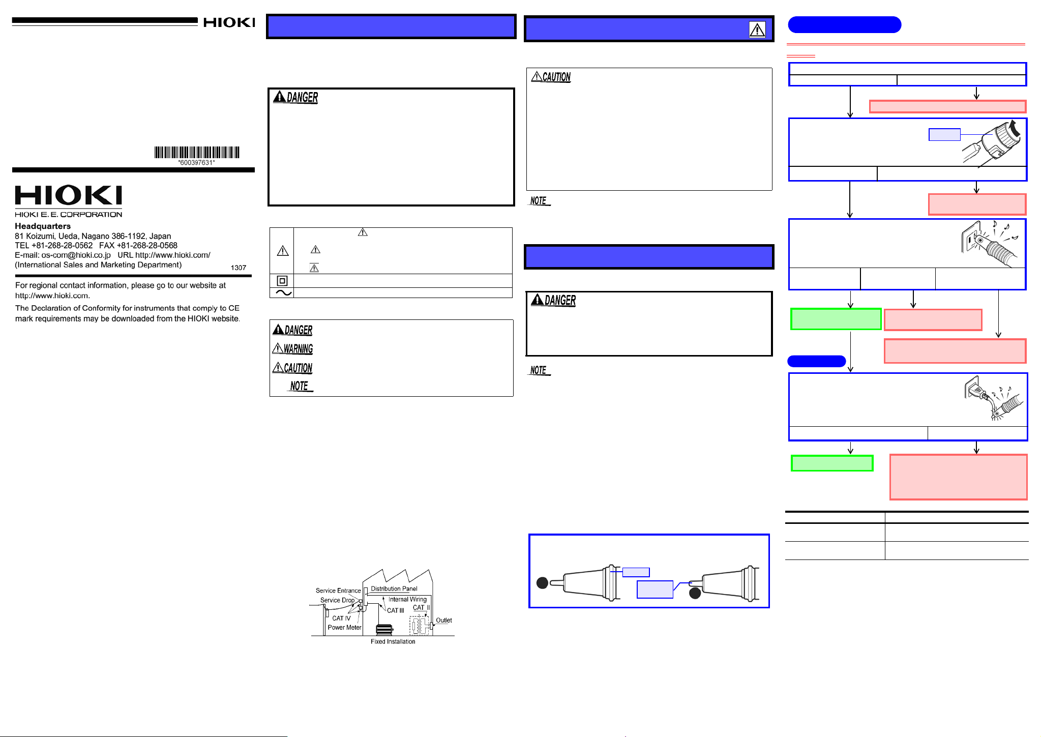
Voltage detection is not
○
performed properly.
it is parallel to the object.
Position the detecting element so that
Detecting
element
Barrier
and the buzzer sounds. or the buzzer does not sound.
sound are getting off.
The red LED lights up The red LED does not light up
The red LED and buzzer
The green LED is still lighting up.
The red LED lights up and the buzzer sounds.
Performance Check
Detection
OK
OK
NG
2. Turn the switch ON.
(Turn it clockwise.)
3. Grip the 3120-21 firmly and apply the de-
tecting element to a known power supply
(e.g., AC outlet) in order to check the
performance.
Turn on the switch. In the state that the green LED
is lighting up, apply the detecting element to the object to be measured. If there are several wires, conduct a voltage check of each wire separately. (Check
some points for bundle of wires.)
The object cannot perform voltage
detection. (It is not live or the earth
potential is below the measurementvoltage range (70 V or less).)
The green LED lights up.
The batteries are runningThe 3120-21 is operating
The 3120-21 may be malfunctioning.
properly. It can be used.
Do not use it.
The object is live.
Switch
1. Inspect the 3120-21 carefully to ensure that no damage.
There is no damage. The 3120-21 is damaged.
Be sure to check the following before use to avoid electrical
Contact your dealer or Hioki representative.
OK
NG
low. Replace the batteries.
NG
NG
The batteries are running
low. Replace the batteries.
shock.
The green LED does not light up or is dim.
Warranty
Warranty malfunctions occurring under conditions of normal use
in conformity with the Instruction Manual and Product Precautionary Markings will be repaired free of charge. This warranty
is valid for a period of three (3) years fro m the date of purchas e.
Please contact the distributor from which you purchased the
product for further information on warranty provisions.
Introduction
Thank you for purchasing the HIOK I “Model 3120- 21 VOLTAGE
DETECTOR.” To obt ain maximum per formance f rom the instrument, please read this manual first, and keep it handy for future
reference.
Overview
This noncontact type of voltage detector unit enables the hot-line
state of AC voltage to be checked through the wire or cable covering.
Initial Inspection
When you receive the instrument, inspect it carefull y to ensure
that no damage occurred during shipping. If damag e is evid ent,
or if it fails to operate according to the specifications, contact your
dealer or Hioki representative.
Maintenance and Service
• To clean the instrument, wipe it gently with a soft cloth moistened with water or mild detergent. Never use solvents such
as benzene, alcohol, acetone, ethe r, ketones, thinne rs or gasoline, as they can deform and discolor the case.
• If the instrument seems to be malfunctioning, confirm that the
batteries are not discharged, before contacting your dealer or
Hioki representative.
Safety
This manual contains information and warnings essential for safe
operation of the instrument and for maintaining it in safe operating
condition. Before using it, be sure to carefully read t he following
safety precautions.
This instrument is designed to comply with IEC 61010
Safety Standards, and has been thoroughly tested for
safety prior to shipment. However, mishandling during
use could result in injury or death, as well as damage to
the instrument. Using the instrument in a way not
described in this manual may n egate the provid ed safety
features. Be certain that you understand the instructions
and precautions in the m anual before use. We disclaim
any responsibility for accidents or injuries not resulting
directly from instrument defects.
Safety Symbol
In the manual, the symbol indicates particularly important
information that the user should read before using the instr ument.
The symbol printed on the instrument indicates that the user
should refer to a corresponding topic in the manual (marked with
the symbol) before using the relevant function.
Indicates a double-insulated device.
Indicates AC (Alternating Current).
The following symbols in this manual indicate the relative importance of cautions and warnings.
Indicates that incorrect operation presents an extrem e hazard that could result in serious injury or death to the user.
Indicates that incorrect operation presents a significant hazard that could result in serious injury or death to the user.
Indicates that incorrect operation presents a possibility of
injury to the user or damage to the device.
Indicates advisory items related to performance or correct
operation of the instrument.
Measurement categories
This instrument complies with CAT IV (1000 V) safety requirements. To ensure safe operation of measurement instruments,
IEC 61010 establishes safety standards for various electrical
environments, categorized as CAT II to CAT IV, and called
measurement categories.
CAT II: Primary elec trical circuit s in equipment connec ted to an
AC electrical outlet by a power cord (portable tools,
household appliances, etc.)
CAT II covers directly measuring electrical out let receptacles.
CAT III:Primary electrical circuits of heavy equipment (fixed
installations) connected directly to the distribution
panel, and feeders from the distribution panel to outlets.
CAT IV: The circuit from the service drop to the service
entrance, and to the power meter and primary overcurrent protection device (distribution panel).
Using a measurement instrument in an environment designated with a higher-numbered category than that for which the
instrument is rated could result in a severe accident, and must
be carefully avoided.
Use of a measurement instrument that is not CAT-rated in CAT
II to CAT IV measurement applications could result in a severe
accident, and must be carefully avoided.
Usage Notes
Follow these precautions to ensure safe operation an d to obtain the
full benefits of the various functions.
• This instrument is designed for use indoors. It can be operated at temperatures between 0 and 40°C without degradin g
safety.
• This instrument is not designed to be entirely water- or dust proof. Do not use it in an especially dusty environment, nor
where it might be splashed with liquid. This may cause damage.
• To avoid damage to the instrument, protect it from physical
shock when transporting and handling . Be especially ca reful
to avoid physical shock from dropping.
A weak green light indicates dead battery . Replace th e batteries immediately.
Detection
Performance Check and Voltage Detection
The maximum rated voltage between input terminals and
ground is 1000 V AC. Attempting to measure voltages
exceeding 1000 V with respect to ground could damage
the instrument and result in personal injury.
• The green LED indicates battery consumption but is not a
guarantee of the performance of the instrument. Be sure to
check its performance using a known power source (e.g., AC
outlet) prior to use.
• The 3120-21 voltage detect or works us ing a live AC circuit. It
will not work using an earthed wire or neutral point. If there
are several lines, such as 2-phase wires and 3-phase wires,
perform voltage detection on each line separately.
• The 3120-21 cannot perform voltage detection on a shielded
wire.
• Be sure to grip the 3120-21 firmly during measurement. But,
do not touch the portion beyond the barrier. It will not produce
any detection.
• Make sure the detec ting el ement p roperly contacts the ob ject
to be measured. (See the right figure.)
3120-21 VOLTAGE DETECTOR
The red LED lights up and the
buzzer sounds.
Only the green LED lights up.
Object to be Measured
Live.
Not live or below the measurement-voltage
range (70 V or less).
Page 2

Replacing the batteries
1
2
3
①
②
Turn the switch off.
Press and hold down the switch, then turn it
counterclockwise to remove the switch section.
Replace the old battery with a new
4
Install the switch section back
into place by holding it down
Replacing the batteries
one. Confirm correct polarity when
installing the new battery .
and turning clockwise.
This mark
should be
[
OFF
].
MEMO
Specifications
• After replacing the batteries, replace the switch section
before using the instrument.
• Battery may explode if mistreated. Do not short-circuit,
recharge, disassemble or dispose of in fire.
• Handle and dispose of batteries in accordance with local
regulations.
• Do not mix old and new batteries, or different types of batteries. Also, be careful to observe battery polarity during
installation. Otherwise, poor performance or damage from
battery leakage could result.
• Use R03 manganese battery or LR03 alkaline battery.
• After use, always turn OFF the power.
Basic Specifications
Measurement function Detection
Measurement voltage
Measurement frequency 50/60 Hz
Pilot light
Battery check
Power supply
Dimensions
Mass
Operating environment Indoors, altitude up to 2000 m (6562-ft.)
Operating temperature and
humidity range
Storage temperatu re and
humidity range
Accessories
Standards Safety
applying
70 to 1000 VAC (when in contact with an
2
or equivalent insulated wire)
IV2mm
The red LED lights up and the buzzer
sounds when the wire is live.
The green LED is dim or out when the
batteries are low.
Two R03 manganese batteries or Two
LR03 alkaline batteries.
Approx. 149 H 18.5 mm
(5.87”H
0.73”) (excluding projections)
Approx. 38 g (1.3 oz.)
(including two R03 manganese batteries)
0 to 40°C (32 to 104
(with no condensation)
-20 to 60°C (68 to 140°F), 80%RH max.
(with no condensation)
Instruction manual
Two R03 manganese batteries
(For monitor built into the main unit)
EN61010 degree2,
Measurement category IV 1000 V
(
anticipated transient overvoltage 12000 V)
EN61326
EMC
°F
), 80%RH max.
Electrical Specifications
Maximum rated voltage to
earth
Dielectric strength 13.18 kVrms
Rated supply voltage
Operating supply-voltage
range
Maximum rated power
Rated power
Continuous operating time
1000 VAC
1.5 VDC 2
From 3.45 V to the voltage at which the
green LED goes out (central value: 2.1 V)
170 mW (Max) Power supply voltage 3.0
VDC
27 mW (Typ) Power supply voltage 3.0
VDC (Power ON Standby state)
R03 manganese batteries: Approx.100
hours
LR03 alkaline batteries: Approx.200 hours
(Power ON Standby state)
 Loading...