

Page 1
3008
S
MULTI TESTER
Instruction Manual
eptember 2013 Revised edition 2
Printed in Japan
3008A981-02 13-09H
Warranty
Warranty malfunctions occurring under conditions of normal
use in conformity with the Instruction Manual and Product
Precautionary Markings will be repaired free of charge. This
warranty is valid for a period of one (1) year from the date of
purchase. Please contact the distributor from which you
purchased the product for further information on warranty
provisions.
Introduction
Thank you for purchasing the HIOKI "Model 3008 MULTI
TESTER." To obtain maximum performance from the
instrument, please read this manual first, and keep it handy for
future reference.
Overview
This tester is designed for maintenance of industrial power
lines (Max 600 VAC,DC).It is designed in safety and complete
protection against shorting accident, High-power fuse protects
up to 50 kA. Supply current limiting resistance of 10 Ω restricts
short-circuit current.
NOTE:The term "industrial power line" refers to electrical lines
This Instruction Manual provides information and warnings
essential for operating this equipment in a safe manner and for
maintaining it in safe operating condition. Before using this
equipment, be sure to carefully read the following safety notes.
that supply power to electrical equipment and
industrial machinery in factories, buildings, etc. It
does not include indoor lines in ordinary residences
(lines protected by fuses or circuit breakers.)
Safety Information
DANGER
Mishandling this instrument during use could result in injury
or death, as well as damage to the instrument. Be certain
that you understand the instructions and precautions in the
manual before use. We disclaim any responsibility for
accidents or injuries not resulting directly from instrument
defects.
Safety symbols
In the manual, this mark indicates explanations which it is
particularly important that the user read before using the
equipment.
The following symbols are used in this Instruction Manual to indicate the
relative importance of cautions and warnings.
DANGER
WARNING
CAUTION
NOTE
Indicates that incorrect operation presents extreme
danger of accident resulting in death or serious injury
to the user.
Indicates that incorrect operation presents significant
danger of accident resulting in death or serious injury
to the user.
Indicates that incorrect operation presents possibility
of injury to the user or damage to the equipment.
Denotes items of advice related to performance of
the equipment or to its correct operation.
Inspection
When the unit is delivered, check and make sure that it has not been
damaged in transit. If the unit is damaged, or fails to operate according
to the specifications, contact your dealer or HIOKI representative.
Operating Precautions
Follow these precautions to ensure safe operation and to obtain the full
benefits of the various functions.
DANGER
Observe the following precautions to avoid electric shock.
Always verify the appropriate setting of the range selector
switch before connecting the test leads. Disconnect the
test leads from the measurement object before switching
the range selector switch.
Before taking a measurement, check the position of the
range switch. Do not measure voltage outside the set
voltage range or voltage at levels in excess of the
measurement limit. Doing so may damage the instrument
or cause an accident resulting in injury or death.
Do not input voltage to the resistance measurement
ranges. Doing so may damage the instrument or cause
an accident resulting in injury or death.
If the end of a test lead short-circuits lines with a voltage
between them, this is very dangerous and can lead to a
serious accident. Exercise great care when measuring
voltage.
WARNING
Before using the unit, inspect it and check the operation
to make sure that the unit was not damaged due to poor
storage or transport conditions. If damage is found,
contact your dealer or HIOKI representative.
To prevent electric shock, do not allow the unit to become
wet and do not use the unit when your hands are wet.
To avoid electric shock when measuring live lines, wear
appropriate protective gear, such as insulated rubber
gloves, boots and a safety helmet.
CAUTION
If the protective functions of the unit are damaged, either
remove the unit from service or post warnings to prevent
others from using the unit inadvertently.
Note that the unit may be damaged if voltage or current in
excess of the measurement range is input.
Do not store or use the unit where it will be exposed to
direct sunlight, high temperatures, high humidity, or
condensation. If exposed to such conditions, the unit may
be damaged, the insulation may deteriorate, and the unit
may no longer satisfy its specifications.
After use, be sure to turn the power switch off.
NOTE
If the meter pointer is not positioned in the 0 scale value, use the zero
adjuster to adjust it correctly.
If the fuse is blown, or the test leads are damaged, any range does
not operate. To check the test leads wiring and fuse blowing, refer to
3. Fuse and Test Leads Continuity Check in Battery and Fuse
Replacement.
If the meter cover becomes electrostatically charged, values may
display incorrectly because of attractive forces on the needle. In this
case, apply anti-static treatment to inhibit electrostatic charge buildup.
The efficacy of such electrostatic treatments dissipates over time, so
the treatment may need to be reapplied periodically.
Measurement Procedure
Pre-Operation Inspection
To avoid the possibility of electric shock or incorrect measurement,
check the following items before using the instrument.
WARNING
Before using the instrument check that the body of the
instrument is not damaged. Also make sure that the
insulation on the test leads is undamaged and that no bare
conductors are improperly exposed.
Using the product in such conditions could cause an electric
shock, so contact your dealer or Hioki representative for
replacements. (Model 9060 TEST LEAD)
For voltage measurement, short the test leads and check that 0 V is
indicated.
For resistance measurement, short the test leads and adjust the
reading to zero using the zero ohm adjuster (0 Ω ADJ knob).
Measure a test item with a known value (battery, AC supply, resistor,
etc.) to check that the instrument is functioning correctly.
Voltage Measurement (AC, DCV)
DANGER
The maximum permissible input is 600 VAC/DC. Do not
measure voltage in excess of these limitations (including the
fuse interrupting rating), as doing so may damage the unit or
cause an accident that might result in injury or death.
1. Set the range selector switch to the ACV or DCV range proper for the
voltage to be measured.
: If the voltage value is unclear, initially set the range switch to the
NOTE
600 V range, and after obtaining a reading in this range, change
to the range proper for the voltage value.
2. Connect the black test lead to the Negative (-) terminal, and the red
one to the Positive (+) terminal.
3. Connect the test leads to the circuit to be measured in parallel, then
read the results on the AC/DC scale. When the DCV is selected, if
connecting the red test lead to the positive side, and the black one to
the negative side, then the pointer deflects normally.
: When changing the range, disconnect the test leads from the
NOTE
object to be measured.
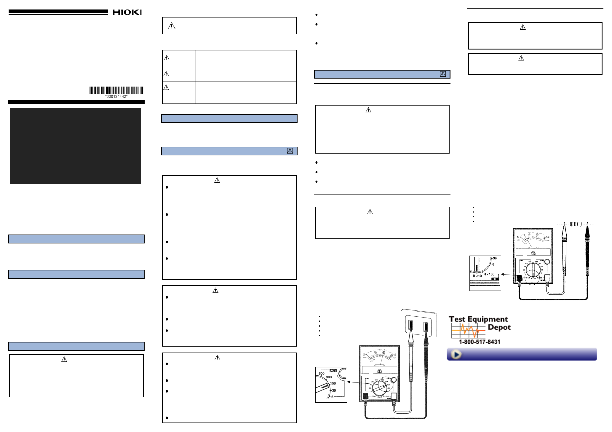
Measurement example
The voltage measurement of the outlet
Function ACV
Range 150 V
Scale AC/DC 150
Measurement value 100 V
Resistance Measurement (Ω )
DANGER
Do not input voltage to the resistance measurement
functions. Doing so may damage the unit or cause an
accident resulting in injury or death.
WARNING
Turn off the power and discharge the capacitors before
measuring resistance in a circuit.
1. Set the range selector switch to the proper Ω range.
Accurate measurement can be made by selecting a range where the
reading will be about the center of the range.
2. Connect the black test lead to the Negative (-) terminal, and the red
one to the Positive (+) terminal.
3. Short the test leads, and use the zero ohm adjuster (0 ΩADJ knob) to
adjust the pointer to the 0 Ω scale.
: If the pointer cannot be adjusted to the 0 Ω scale, replace the
NOTE
battery.
4. Connect the test leads to the circuit to be measured, and read the
value from the scale.
: When changing the range, disconnect the test leads from the
NOTE
object to be measured.
For resistance measurement, the indication may be unstable if the
ends of the test leads are dirty, and the contact is poor. If the
indication is unstable, increase the contact pressure, or clean the
ends of the test leads by wiping with alcohol or similar solvent.
5. In order to obtain the true value, it is necessary to multiply the reading
shown by the factor for the range in use.
Measurement example
5.1kΩ resistance measurement
Function R x 10
Scale Ω
Measurement value 5.1 kΩ
Resistance
99 Washington Street
Melrose, MA 02176
Phone 781-665-1400
Toll Free 1-800-517-8431
Visit us at www.TestEquipmentDepot.com
Page 2
Battery and Fuse Replacement
3. Fuse and Test Leads Continuity Check
Part Names
WARNING
To avoid electric shock when replacing the batteries and
fuse, first disconnect the test leads from the object to be
measured.
After replacing the batteries or fuse, replace the case and
screws before using the instrument.
Fuse
Battery
Battery
1. Battery Replacement
WARNING
Do not mix old and new batteries, or different types of
batteries. Also, be careful to observe battery polarity
during installation. Otherwise, poor performance or
damage from battery leakage could result.
To avoid the possibility of explosion, do not short circuit,
disassemble or incinerate batteries.
Handle and dispose of batteries in accordance with local
regulations.
To avoid corrosion from battery leakage, remove the
batteries from the instrument if it is to be stored for a long
time.
1. Remove the case back screw and take off the case back.
2. Replace the two batteries.
3. After replacing the batteries, always replace the case back and tighten
the screw before using the unit.
2. Fuse Replacement
WARNING
Replace the fuse only with one of the specified
characteristics and voltage and current ratings. Using a
non-specified fuse or shorting the fuse holder may cause
a life-threatening hazard.
Fuse type:Interrupting rating 50 kA,500 V 1 A
1. Remove the case back screw and take off the case back.
2. Replace the fuse with a new one.
:A spare fuse is provided inside the carrying case.
NOTE
Be sure to supply a new spare fuse if the spare fuse is used to
replace a blown fuse.
3. After replacing the fuse, always replace the case back and tighten the
screw before using the unit.
:If the fuse blown, when measuring industrial power lines, there is
NOTE
a possibility of an internal 3008 failure. Replace the fuse and
contact your dealer or HIOKI representative.
1. Connect the black test lead to the Negative (-) terminal, and the red
one to the Positive (+) terminal.
2. Set the range switch to the Ω x 100 range, and short the test leads.
3. If the pointer deflects, the fuse and test leads conduct (are not blown
and damaged).
If the pointer does not deflect, the test leads or fuse may be
damaged. Check again after replacing the fuse.
About the Fuse Type Protective Circuit
This tester is provided with a protective resistor (10 Ω) for prevention of
accidental short circuit in measuring power voltage, and has a 1 A Fuse
(500 V AC,With a Interrupting rating of 50 kA) connected in series from
the terminal (refer to figure.)
If a short circuit occurs in the tester circuit, the protective resistor holds
down the short circuit with the fuse.
As the protective resistor keeps excessive short circuit current from
running, the arc at the tip etc. of the test bar can be held down to the
minimum for greater safety.
Specifications
Accuracy guaranteed for one year at 23
less.)
DCV 0 to 6/30/60/300/600 V
ACV 0 to 6/30/150/300/600 V
Ω
Protection Circuit : Fuse-protected,
Fuse Interrupting rating 50 kA, 500 V
Power supply Rated power voltage 1.5 VDC x 2,
Location for Use Altitude up to 2000 m (6562 feet), indoors
Dimensions and mass Approx. 94W x 134H x 56D mm, Approx. 350 g
Maximum permissible
input
Accessories 9060 TEST LEAD 1
20 kΩ/V ,
10 kΩ/V ,
0to10kΩ, central scale 100 Ω,
R x 1/R x 10/R x 100,
Internal circuit protection using the
10Ω resistance
Meter : Diode-protected
R6P manganese battery x 2
Approx. 3.7"W x 5.28"H x 2.2"D, Approx. 12.3 oz.
600 VAC/DC
Spare fuse (Interrupting rating 50 kA,500 V) 1
manganese battery (R6P) 2
Instruction Manual 1
Carrying case 1
5 (73 9 ), 80%RH or
2.5% of f.s. reading
2.5% of f.s. reading
3% of scale length
Test Equipment Depot - 800.517.8431 - 99 Washington Street Melrose, MA 02176
TestEquipmentDepot.com
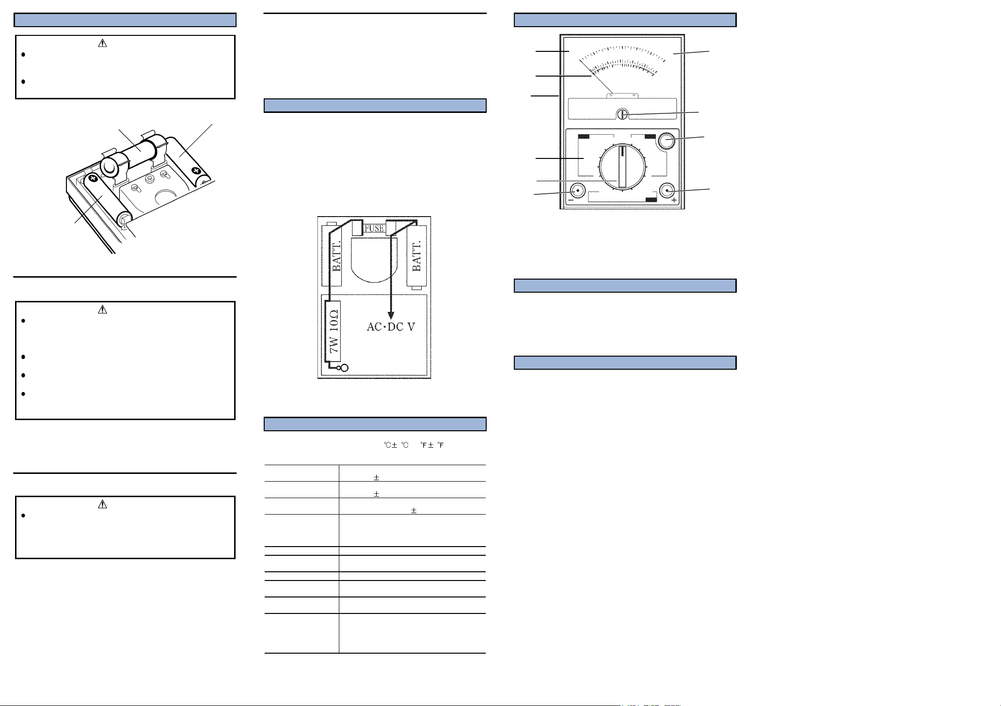
1.
6.
2.
3.
7.
8.
4.
5.
10.
Meter Nomenclature
1. Panel 2. Pointer 3. Case back 4. Face plate
5. Range selector switch 6. Scale plate 7. Zero adjuster
8. Zero ohm adjuster 9. Positive (+) terminal
10. Negative (-) terminal
9.
Maintenance
Gently wipe dirt from the surface of the unit with a soft cloth moistened
with a small amount of water or mild detergent.
Do not try to clean the unit using cleaners containing organic solvents
such as benzine, alcohol, acetone, ether, ketones, thinners, or gasoline.
They may cause discoloration or damage.
Service
If the unit is not functioning properly, check the batteries, the test leads
wiring, and fuse blowing. If a problem is found, contact your dealer or
HIOKI representative. Pack the unit carefully so that it will not be
damaged during transport, and write a detailed description of the
problem. HIOKI cannot bear any responsibility for damage that occurs
during shipment.
 Loading...