

Page 1

Instruction Manual
2300
SMART SITE
February 2011 Revised edition 5 2300A981-05 11-02H
Page 2

Contents
Contents
APPX
I
Introduction.................................................................................1
Safety Notes............... .. .. ... .. ................. .. ... .. ... ................ ... .. ... .. ..1
Notes on Use.. .. .. ... ................................. ... .. ... .. ................. .. ... .. ..4
Service .......................................................................................7
1
2301-20 HUMIDITY MODULE___________________ 9
1.1 Overview .......................................................................9
1.1.1 Product Overview ............................................................9
1.1.2 Major Features ................................................................9
1.1.3 Name and Function of the Parts ...................................12
1.1.4 Dimension Diagrams .................................................. ...1 3
1.1.5 Accessory and Option .................................. ..... ............13
1.2 Settings .......................................................................14
1.2.1 Setting the Module ID ....................................................14
1.3 Preparations................................................................15
1.3.1 Installing the Module .....................................................15
1.3.2 Connecting Input/Output Cables ...................................16
1
2
3
4
5
6
1.4 Others .........................................................................19
1.4.1 Alarm output ........................................ ..... .....................19
1.4.2 Insulation of Internal Circuit ...........................................21
1.5 Specifications..............................................................22
1.5.1 Basic Specifications ......................................................22
1.5.2 Function Specifications .................................................22
1.5.3 General Specifications ..................................................23
1.5.4 9764-50 HUMIDIDTY SENSOR Specifications .............24
2
2302-20 Pt MODULE_________________________ 25
2.1 Overview .....................................................................25
2.1.1 Product Overview ..........................................................25
2.1.2 Major Features ..............................................................25
2.1.3 Name and Function of the Parts ...................................28
2.1.4 Dimension Diagrams .................................................. ...2 9
2.1.5 Accessory and Option .................................. ..... ............29
2.2 Settings .......................................................................30
2.2.1 Setting the Module ID ....................................................30
7
8
9
2.3 Preparations................................................................31
2.3.1 Installing the Module .....................................................31
IDX
Page 3

II
Contents
2.3.2 Connecting Input/Output Cables ...................................31
2.4 Others......................................................................... 34
2.4.1 Alarm output .................................................................34
2.4.2 Insulation of Internal Circuit ..........................................36
2.5 Specifications ............................................................. 37
2.5.1 Basic Specifications ......................................................37
2.5.2 Function Specifications ....................... .... ..... ..... ............37
2.5.3 General Specifications ..................................................38
3
2303-20 TC MODULE ________________________39
3.1 Overview..................................................................... 39
3.1.1 Product Overview .........................................................39
3.1.2 Major Features ..............................................................39
3.1.3 Name and Function of the Parts ..................................42
3.1.4 Dimension Diagrams ....................................................43
3.1.5 Accessory and Option ...................................................43
3.2 Settings....................................................................... 44
3.2.1 Setting the Module ID ...................................................44
3.3 Preparations...............................................................45
3.3.1 Installing the Module .....................................................45
3.3.2 Connecting Input/Output Cables ...................................45
3.4 Others......................................................................... 49
3.4.1 Alarm output .................................................................49
3.4.2 Insulation of Internal Circuit ..........................................51
3.5 Specifications ............................................................. 52
3.5.1 Basic Specifications ......................................................52
3.5.2 Function Specifications ....................... .... ..... ..... ............53
3.5.3 General Specifications ..................................................53
4
2304-20 PULSE MODULE_____________________55
4.1 Overview..................................................................... 55
4.1.1 Product Overview .........................................................55
4.1.2 Major Features ..............................................................56
4.1.3 Name and Function of the Parts ..................................58
4.1.4 Dimension Diagrams ....................................................59
4.1.5 Accessory and Option ...................................................59
4.2 Settings....................................................................... 60
4.2.1 Setting the Module ID ...................................................60
4.3 Preparations...............................................................61
4.3.1 Installing the Module .....................................................61
4.3.2 Connecting Input/Output Cables ...................................61
Page 4

Contents
APPX
4.4 Others .........................................................................66
4.4.1 Examples of Voltage/Contact Output Dev ice Connection 66
4.4.2 Alarm output ........................................ ..... .....................68
4.4.3 Insulation of Internal Circuit ...........................................70
4.5 Specifications..............................................................71
4.5.1 Basic Specifications ......................................................71
4.5.2 Function Specifications .................................................72
4.5.3 General Specifications ..................................................72
5
2304-21 PULSE MODULE ____________________ 75
5.1 Overview .....................................................................75
5.1.1 Product Overview ..........................................................75
5.1.2 Major Features ..............................................................76
5.1.3 Name and Function of the Parts ...................................78
5.1.4 Dimension Diagrams .................................................. ...7 9
5.1.5 Accessory and Option .................................. ..... ............79
5.2 Settings .......................................................................80
5.2.1 Setting the Module ID ....................................................80
III
1
2
3
4
5
5.3 Preparations................................................................81
5.3.1 Installing the Module .....................................................81
5.3.2 Connecting Input/Output Cables ...................................81
5.4 Others .........................................................................85
5.4.1 Examples of Connections According to Type of Device
Coupled .........................................................................85
5.4.2 Alarm output ........................................ ..... .....................87
5.4.3 Insulation of Internal Circuit ...........................................89
5.5 Specifications..............................................................90
5.5.1 Basic Specifications ......................................................90
5.5.2 Function Specifications .................................................90
5.5.3 General Specifications ..................................................91
6
2305-20 INSTRUMENTATION MODULE _________ 93
6.1 Overview .....................................................................93
6.1.1 Product Overview ..........................................................93
6.1.2 Major Features ..............................................................94
6.1.3 Name and Function of the Parts ...................................96
6.1.4 Dimension Diagrams .................................................. ...9 7
6.1.5 Accessory and Option .................................. ..... ............97
6
7
8
9
6.2 Settings .......................................................................98
6.2.1 Setting the Module ID ....................................................98
6.3 Preparations................................................................99
IDX
Page 5

IV
Contents
6.3.1 Installing the Module .....................................................99
6.3.2 Connecting Input/Output Cables ...................................99
6.4 Others....................................................................... 102
6.4.1 Alarm Output ...............................................................102
6.4.2 Insulation of Internal Circuit ........................................104
6.5 Specifications ........................................................... 105
6.5.1 Basic Specifications ....................................................105
6.5.2 Function Specifications ....................... .... ..... ..... ..........105
6.5.3 General Specifications ................................................106
7
2306-20 MULTIFUNCTION MODULE___________107
7.1 Overview................................................................... 107
7.1.1 Product Overview .......................................................107
7.1.2 Major Features ............................................................108
7.1.3 Name and Function of the Parts ................................110
7.1.4 Dimension Diagrams ..................................................111
7.1.5 Accessory and Option .................................................111
7.2 Settings..................................................................... 112
7.2.1 Setting the Module ID .................................................112
7.3 Preparations.............................................................113
7.3.1 Installing the Module ...................................................113
7.3.2 Paste the seal to the terminal block. ...........................114
7.3.3 Connecting Input/Output Cables .................................114
7.3.4 Procedure for connecting to the terminal ....................115
7.4 Digital filter................................................................ 120
7.5 Others....................................................................... 121
7.5.1 Insulation of Internal Circuit ........................................121
7.5.2 Measurement method .................................................121
7.5.3 Pre-heating time before the start of recording ............122
7.5.4 Function to detect broken wires when using a
thermocouple .............................................................. 123
7.6 Specifications ........................................................... 124
7.6.1 Basic Specifications ....................................................124
7.6.2 Function Specifications ....................... .... ..... ..... ..........125
7.6.3 General Specifications ................................................126
8
2321-20 WAVEFORM MODULE _______________127
8.1 Overview................................................................... 127
8.1.1 Product Overview .......................................................127
8.1.2 Major Features ............................................................128
8.1.3 Name and Function of the Parts .................................130
Page 6

Contents
APPX
8.1.4 Dimension Diagrams .................................................. .132
8.1.5 Accessory and Option .................................. ..... ..........133
8.2 Settings .....................................................................133
8.3 Preparations..............................................................134
8.3.1 Installing the Module ...................................................134
8.3.2 Connect the signal input cable ....................................135
8.3.3 Connect the trigger input signal ...................................138
8.3.4 Connect the trigger output signal ... ..... ..... .... ...............139
8.4 Recording dat a..... ................. ............................... .....141
8.5 Insulation of Internal Circuit.......................................144
V
1
2
8.6 Trigger applicatio n ex am p le.............. .. ................. .. ...1 4 5
8.7 Specifications............................................................153
8.7.1 Basic Specifications ....................................................153
8.7.2 Function Specifications ...............................................154
8.7.3 General Specifications ................................................157
8.8 Disposing of the Instrument ......................................158
9
2331-20 POWER METER MODULE____________ 159
9.1 Overview ...................................................................159
9.1.1 Product Overview ........................................................159
9.1.2 Major Features ............................................................160
9.1.3 Name and Function of the Parts ..................................166
9.1.4 Dimension Diagrams .................................................. .167
9.1.5 Accessory and Option .................................. ..... ..........168
9.2 Settings .....................................................................169
9.2.1 Setting the Module ID ..................................................169
3
4
5
6
7
8
9.3 Preparations..............................................................170
9.3.1 Installing the Module ...................................................170
9.3.2 Connecting the Clamp Sensor to Module ....................171
9.3.3 Connecting the Voltage Cable to the Module ..............172
9.3.4 Connecting Alarm Output ............................................173
9.3.5 Connecting to the Measured Line ...............................174
9.4 Others .......................................................................178
9.4.1 Alarm Output .................................. ..... ..... ...................178
9.4.2 Insulation of Internal Circuit .........................................179
9.5 Specifications............................................................180
9.5.1 Basic Specifications ....................................................180
9.5.2 Function Specifications ...............................................182
9.5.3 General Specifications ................................................183
9
IDX
Page 7

VI
Contents
10
2332-20 POWER METER MODULE ____________185
10.1 Overview................................................................... 185
10.1.1 Product Overview .......................................................185
10.1.2 Major Features ............................................................186
10.1.3 Name and Function of the Parts .................................192
10.1.4 Dimension Diagrams ..................................................194
10.1.5 Accessory and Option .................................................195
10.2 Settings..................................................................... 196
10.2.1 Setting the Module ID .................................................196
10.3 Preparations.............................................................197
10.3.1 Installing the Module ...................................................197
10.3.2 Connecting the Clamp Sensor to Module ...................198
10.3.3 Connecting the Voltage Cable to the Module .............200
10.3.4 Connecting to the Measured Line ...............................201
10.4 Others....................................................................... 205
10.4.1 Alarm Assessment ......................................................205
10.4.2 Insulation of Internal Circuit ........................................205
10.5 Specifications ........................................................... 206
10.5.1 Basic Specifications ....................................................206
10.5.2 Function Specifications ..................................... .... ......208
10.5.3 General Specifications ................................................209
11
2341-20 INPUT MODULE ____________________211
11.1 Overview................................................................... 211
11.1.1 Product Overview .......................................................211
11.1.2 Major Features ............................................................211
11.1.3 Name and Function of the Parts .................................212
11.1.4 Dimension Diagrams ..................................................214
11.1.5 Accessory and Option .................................................214
11.2 Settings..................................................................... 215
11.3 Preparations.............................................................216
11.3.1 Installing the Module ...................................................216
11.3.2 Connecting Input/Output Cables .................................217
11.4 Others....................................................................... 219
11.4.1 Internal Circuit ................................................... .... ......219
11.4.2 Examples of Connections According to Type of Device
Coupled ......................................................................220
11.4.3 Insulation of Internal Circuit ........................................222
11.5 Specifications ........................................................... 223
11.5.1 Basic Specifications ....................................................223
11.5.2 Function Specifications ..................................... .... ......223
Page 8

Contents
11.5.3 General Specifications ................................................224
12 2342-20 OUTPUT MODULE _______________ 225
12.1 Overview ...................................................................225
12.1.1 Product Overview ........................................................225
12.1.2 Major Features ............................................................225
12.1.3 Name and Function of the Parts ..................................226
12.1.4 Dimension Diagrams ................................ .... ..... ..... .....227
12.1.5 Accessory and Option ............................................ .... .227
12.2 Settings .....................................................................228
VII
11
12
12.3 Preparations..............................................................229
12.3.1 Installing the Module ...................................................229
12.3.2 Connecting Input/Output Cables .................................229
12.4 Others .......................................................................231
12.4.1 Output Circuit .................................................... ..... .... .231
12.4.2 Examples of Connections According to Type of Device
Coupled .......................................................................233
12.4.3 Insulation of Internal Circuit .......................... ...............237
12.5 Specifications............................................................238
12.5.1 Basic Specifications ....................................................238
12.5.2 Function Specifications ...............................................238
12.5.3 Each Channel Output Function ...................................239
12.5.4 General Specifications ................................................239
13
2343-20 RS LINK MODULE __________________ 241
13.1 Overview ...................................................................241
13.1.1 Product Overview ........................................................241
13.1.2 Major Features ............................................................241
13.1.3 Name and Function of the Parts ..................................242
13.1.4 Dimension Diagrams ................................ .... ..... ..... .....243
13.1.5 Accessory and Option ............................................ .... .243
13
13.2 Settings .....................................................................244
13.2.1 Setting the Module ID ..................................................244
13.3 Preparations..............................................................245
13.3.1 Installing the Module ...................................................245
13.3.2 Connecting RS-232C Cable to the Module .................246
13.4 Specifications............................................................247
13.4.1 Basic Specifications ....................................................247
13.4.2 Function Specifications ...............................................247
13.4.3 General Specifications ................................................248
10
Page 9

VIII
Contents
14
2351 AIR MODULE
2352-20 WIRE MODULE ____________________ _249
14.1 Overview................................................................... 249
14.1.1 Product Overview .......................................................249
14.1.2 Major Features ............................................................250
14.1.3 Name and Function of the Parts .................................251
14.1.4 Dimension Diagrams ..................................................252
14.1.5 Accessory and Option .................................................252
14.2 Settings..................................................................... 253
14.2.1 Setting the COM ID .....................................................253
14.3 Preparations.............................................................254
14.3.1 Installing the Module ...................................................254
14.3.2 Connecting Sending/Receiving
Antenna to Module (2351 Only) ..................................255
14.3.3 How to install the antennae ........................................256
14.3.4 Connecting RS-232C Cable to Module .......................258
14.4 Specifications ........................................................... 259
14.4.1 Basic Specifications ....................................................259
14.4.2 Function Specifications ..................................... .... ......260
14.4.3 General Specifications ................................................260
14.5 Disposing of the Instrument...................................... 261
15
2353-20 LAN MODULE ______________________263
15.1 Overview................................................................... 263
15.1.1 Product Overview .......................................................263
15.1.2 Major Features ............................................................263
15.1.3 Name and Function of the Parts .................................264
15.1.4 Dimension Diagrams ..................................................265
15.1.5 Accessory and Option .................................................265
15.2 Settings..................................................................... 266
15.2.1 Setting the COM ID .....................................................266
15.3 Preparations.............................................................267
15.3.1 Installing the Module ...................................................267
15.3.2 Connecting the LAN Cable .........................................268
15.3.3 Setting the IP Address ................................................269
15.4 Specifications ........................................................... 270
15.4.1 Basic Specifications ....................................................270
15.4.2 Function Specifications ..................................... .... ......270
15.4.3 General Specifications ................................................270
15.5 Disposing of the Instrument...................................... 271
Page 10

Contents
16
2354-20 MEMORY MODULE _________________ 273
16.1 Overview ...................................................................273
16.1.1 Product Overview ........................................................273
16.1.2 Major Features ............................................................274
16.1.3 Name and Function of the Parts ..................................274
16.1.4 Dimension Diagrams ................................ .... ..... ..... .....276
16.1.5 Accessory and Option ............................................ .... .276
16.2 Settings .....................................................................277
16.2.1 Setting the COM ID .....................................................277
16.3 Preparations..............................................................278
16.3.1 Installing the Module ...................................................278
16.3.2 Connecting the LAN Cable ..........................................279
IX
16.4 Other .........................................................................280
16.4.1 For CF card ............. ............................ ..... .... ..... ..........280
16.4.2 Recording operation ....................................................283
16.4.3 Setting the IP Address ................................................285
16.5 Specifications............................................................286
16.5.1 Basic Specifications ....................................................286
16.5.2 Function Specifications................................................286
16.5.3 Data recorded Specifications ................... .... ..... ..........287
16.5.4 General Specifications ................................................287
16.6 Disposing of the Instrument ......................................288
17
2361-20 AC POWER MODULE _______________ 289
17.1 Overview ...................................................................289
17.1.1 Product Overview ........................................................289
17.1.2 Major Features ............................................................289
17.1.3 Name and Function of the Parts ..................................290
17.1.4 Dimension Diagrams ................................ .... ..... ..... .....291
17.1.5 Accessory and Option ............................................ .... .291
14
15
16
17
17.2 Preparations..............................................................292
17.2.1 Installing the Module ...................................................292
17.2.2 Connecting Power Cable .............................................293
17.3 Specifications............................................................295
17.3.1 Basic Specifications ....................................................295
17.3.2 Function Specifications ...............................................295
17.3.3 General Specifications ................................................295
Page 11

X
Contents
18
2362-20 DC POWER MODULE________________297
18.1 Overview................................................................... 297
18.1.1 Product Overview .......................................................297
18.1.2 Major Features ............................................................297
18.1.3 Name and Function of the Parts .................................298
18.1.4 Dimension Diagrams ..................................................299
18.1.5 Accessory and Option .................................................299
18.2 Preparations.............................................................300
18.2.1 Installing the Module ...................................................300
18.2.2 Connecting Power Cable ............................................301
18.3 Specifications ........................................................... 303
18.3.1 Basic Specifications ....................................................303
18.3.2 Function Specifications ..................................... .... ......303
18.3.3 General Specifications ................................................303
19
2391-01, 2391-02, 2391-03 MODULE BASE _____305
19.1 Overview................................................................... 305
19.1.1 Product Overview .......................................................305
19.1.2 Major Features ............................................................306
19.1.3 Name and Function of the Parts .................................306
19.1.4 Dimension Diagrams ..................................................308
19.1.5 Accessory and Option .................................................310
19.2 Preparations.............................................................311
19.2.1 Installing the Module ...................................................311
19.2.2 Connecting Power Supply Output Cord
(2391-01 only) .............................................................314
19.2.3 Connecting the CAN Cable .........................................315
19.3 Specifications ........................................................... 317
19.3.1 Basic Specifications ....................................................317
19.3.2 Function Specifications ..................................... .... ......318
19.3.3 General Specifications.................................................318
20
2392-01/02 MODULE BASE __________________319
20.1 Overview................................................................... 319
20.1.1 Product Overview .......................................................319
20.1.2 Major Features ............................................................319
20.1.3 Name and Function of the Parts .................................320
20.1.4 Dimension Diagrams ..................................................323
20.1.5 Accessory and Option .................................................324
20.2 Preparations.............................................................325
Page 12

Contents
APPX
20.2.1 Installing the Module ...................................................325
20.2.2 Connecting Power Supply Output Cord
(2392-01 only) .......................................... .... ..... ..... .....328
20.2.3 Connecting the CAN Cable .........................................329
XI
20.3 Specifications............................................................331
20.3.1 Basic Specifications ....................................................331
20.3.2 Function Specifications ...............................................331
20.3.3 General Specifications ................................................331
21
Maintenance and Service ___________________ 333
21.1 Cleaning....................................................................333
21.2 Servicing ...................................................................333
11
12
13
14
15
16
17
18
19
20
21
IDX
Page 13

XII
Contents
Page 14
APPX
Introduction
Thank you for purchasing the HIOKI “2300 Smart Site”. To obtain
maximum performance from the instrument, please read this manual first, and keep it handy for future reference.
When you receive the instrument, inspect it carefully to ensure that
no damage occurred during shipping. In particular, check the
accessories, panel switches, and connectors. If damage is evident,
or if it fails to operate according to the specifications, contact your
dealer or Hioki representative.
Safety Notes
This instrument is designed to comply with IEC 61010 Safety
Standards, and has been thoroughly tested for safety prior to
shipment. However, mishandling during use could result in
injury or death, as well as damage to the instrument. Using
the instrument in a way not described in this manual may
negate the provided safety features. Be certain that you
understand the instructions and precautions in the manual
before use. We disclaim any responsibility for accidents or
injuries not resulting directly from instrument defects.
Introduction
1
1
1
2
2
3
3
4
4
16
5
5
6
6
This manual contains information and warnings essen tial for safe
operation of the instrument and for maintaining it in safe operating
condition. Before using it, be sure to carefully read the following
safety precautions.
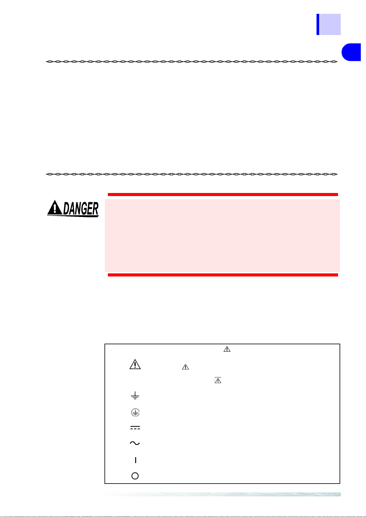
Safety Symbols
In the manual, the symbol indicates particularly important
information t hat the u ser sh ou ld read be fo re u s ing the instrument.
The symbol printed on the instrument indicates that the
user should refer to a corresponding topic in the manual
(marked with the symbol) before using the relevant function.
Indicates a grounding terminal.
Indicates a protective conductor terminal.
Indicates DC (Direct Current).
Indicates AC (Alternating Current).
Indicates the ON side of the power switch.
7
7
8
8
9
9
10
10
11
Indicates the OFF side of the power switch.
IDX
Page 15
2
Safety Notes
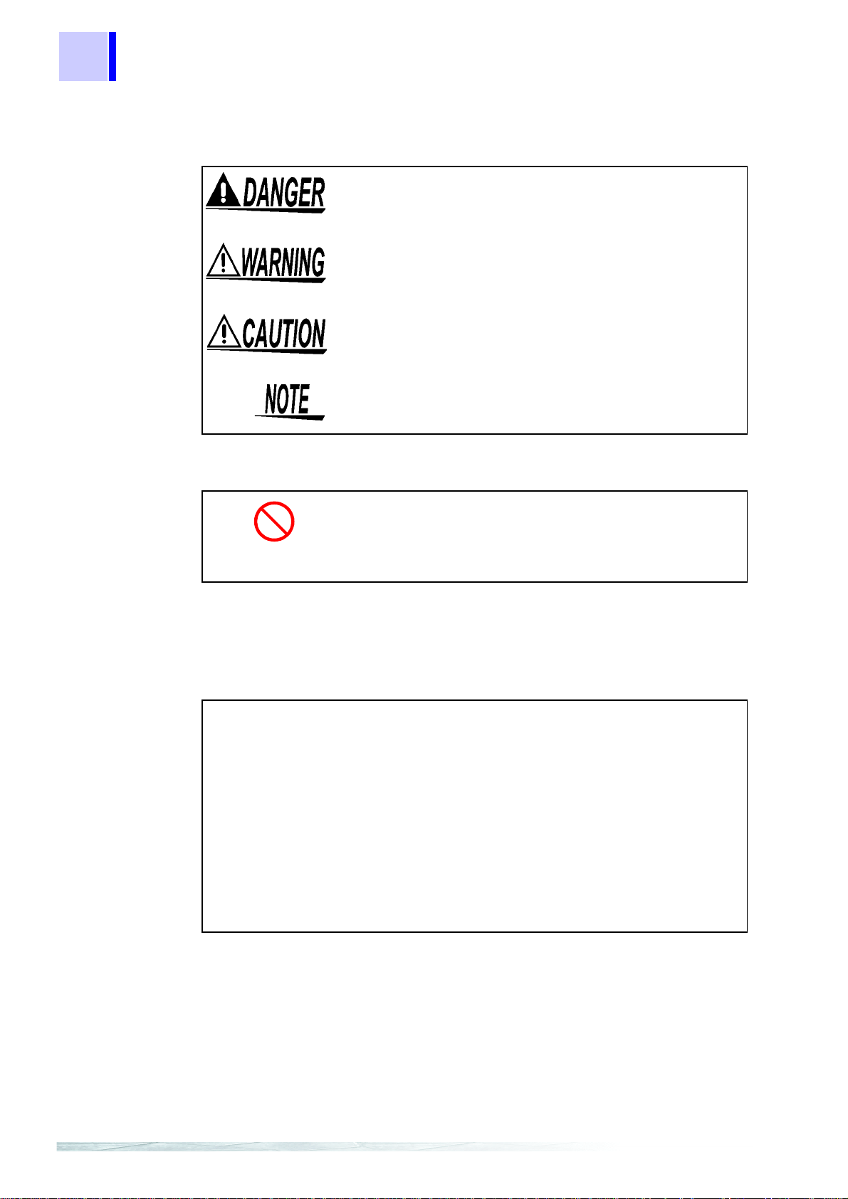
The following symbols in this manual indicate the relative importance of cautions and warnings.
Indicates that incorrect operation presents an
extreme hazard that could result in serious injury
or death to the user.
Indicates that incorrect operation presents a significant hazard that could result in seriou s injury
or death to the user.
Indicates that incorrect operation presents a possibility of injury to the user or damage to the
instrument.
Indicates advisory items related to perfo rmance
or correct operation of the instrument.
Other Symbols
Indicates the prohibited action.
❖
Indicates the reference.
Accuracy
We define measurement tolerances in terms of f.s. (full scale), rdg.
(reading) and dgt. (digit) values, with the following meanings:
f.s.
(maximum
display value or
scale lengt h)
rdg.
(reading or
displayed value)
dgt.
(resolution)
The maximum displayable value or scale
length. This is usually the name of the currently
selected range.
The value currently being measured and indicated on the measuring instrument.
The smallest displayable unit on a digital measuring instrument, i.e., the input value that
causes the digital display to show a "1" as the
least-significant digit.
Page 16
3
APPX
Safety Notes
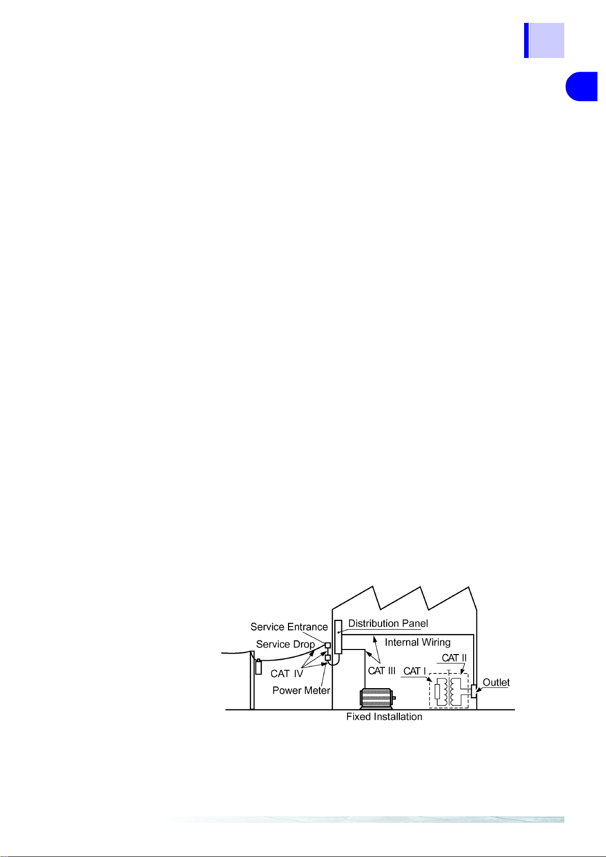
Measurement categories (Ove rvoltage categories)
Model 2301-20, 2302-20, 2303-20, 2304-20, 2304-21 and 2305-20
comply with CAT I safety requirements.
Model 2331-20 and 2332-20 comply with CAT III safety requirements.
To ensure safe operation of measurement ins truments, IEC 61010
establishes safety standards for various electrical environments,
categorized as CAT I to CAT IV, and calle d measurement categories. These are defined as follows.
CAT I Secondary electrical circuits connected to an AC electrical
outlet through a transformer or similar instrument.
CAT II Primary electrical circuits in equipme nt connected to a n AC
electrical outlet by a power cord (portable tools, household
appliances, etc.)
CAT II covers directly me asuring el ectrical outle t recept acles.
CAT III Primary electrical circuits of heavy equipment (fixed installa-
tions) connected directly to the distribution panel, and feeders
from the distribution panel to outlets.
CAT I V The circui t from the service d rop to t he service e ntrance, and
to the power meter and prim ary overcur ren t protec tion inst rument (distribution panel).
1
1
2
2
3
3
4
4
16
5
5
Higher-numbered categories correspond to electrical environments
with greater momentary energy. So a measurement instrument
designed for CAT III environments can endure greater momentary
energy than a instrument designed for CAT II.
Using a measurement instrument in an environment designated
with a higher-numbered category than that for which the instrument
is rated could result in a severe accident, and must be carefully
avoided.
Never use a CAT I measuring instrument in CAT II, III, or IV environments.
The measurement categories comply with the Overvoltage Categories of the IEC60664 Standards.
6
6
7
7
8
8
9
9
10
10
11
IDX
Page 17
4
Notes on Use
Notes on Use
Follow these precautions to ensure safe operation and to obtain
the full benefits of the various functions.
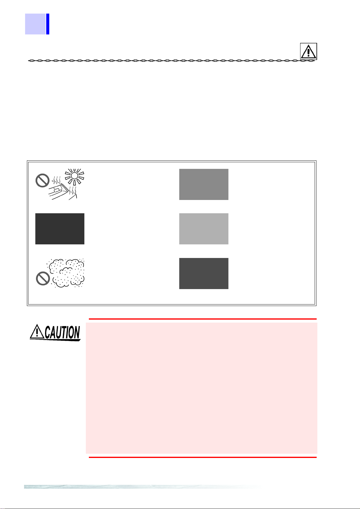
Instrument Installation
Operating temperature and humidity: 0 to 50°C (32 to 122°F), 80%
RH (non-condensating)
Avoid the following locations that could cause an accident or damage to the instrument.
Exposed to direct
sunlight
Exposed to high
temperature
Exposed to liquids
Exposed to
high humidity or condensation
Exposed to high levels
of particulate dust
When the module is used in
a dusty environment, place it
in a dustproof case and take
measures to ensure heat
dissipation.
Do not allow the instrument to get wet, and do not take measurements with wet hands.
The instrument may be damaged.
In the presence of
corrosive or explosive
gases
Exposed to strong
electrom agnetic fields
Near electromagnetic
radiators
Subject to vibration
To avoid damage to the instrument, protect it from physical shock
when transporting and handling.
Be especially careful to avoid physical shock from dropping.
Do not obstruct the ventilation holes.
Ventilation holes for heat radiation are provided on the top and rear
panels of the instrument. Leave sufficient space around the ventilation
holes and install th e instrum ent wi th the ho les uno bstru cted. Installation
of the instrument with the ventilation holes obstructed may cause a
malfunction or fire.
When using the instrument in the case, drill ventilation holes.
Drill ventilation holes or install a ventilation fan to p revent heat buildup.
Page 18

5
APPX
Notes on Use
Only use sensors dedicated to the type of module.
To avoid damaging the ins trument, do not connec t any other sensors
than those dedicated to the instrument to its input terminals. Furth er, do
not connect any other signal sources to the terminals, as such signals
may lead to module damage due to excessive voltage or current.
1
1
Wiring
• A qualified electrician shall perform the wiring to prevent
electric shock.
• Avoid live-line electrical work to prevent electric shock and
accidents due to short-circuiting.
• Ensure that the power supply, input, and output are correctly wired according to the wiring diagram. (See the section on "Preparations" for each module.) This will prevent
fire, malfunction, and errors.
Connect the module to a power source that matches the
rating in order to prevent fire.
• Do not work on live lines. Such work may result in electric
shock or short-circuiting.
• Use cables of the proper sizes for the rated current. This
will prevent entire system errors and fire resulting from
broken wire.
• Use crimp connectors suitable for the cable sizes. This will
prevent module errors and fire due to broken wires.
• When tightening the screws, confirm that all screws are
securely tightened. A loose screw may result in module
errors, fire, or electric shock.
• Tighten the screws within the s pecified torque. Excessive
torque may damage the terminals. Inadequate torque may
result in module errors, fire, or electric shock.
2
2
3
3
4
4
16
5
5
6
6
7
7
8
8
• Ensure that the power supply module and input are OFF
until all wiring work is finished. This will prevent module
trouble and electric shock.
• Ensure that the power supply module and input are OFF
when connecting or disconnecting the module to the system. This will prevent electric shock, errors, and malfunction.
• Avoid using an unused terminal for relaying or any other
purpose to prevent electric shock, errors, and malfunction.
9
9
10
10
11
IDX
Page 19

6
Notes on Use
• If power supply noise poses a problem, use of a noise filter is
recommended.
• When the power and sig nal lines may be subject to a lightninginduced surge, install a lightning arrester between another
instrument or module connected to this module and line to protect the system.
• Avoid stepping on or pinching cables, which could damage the
cable insulation.
• Keep the cables well aw ay from heat sources, as bare conductors could be exposed if the insulation melts.
Preliminary Checks
Before using the instrument, make sure that the insulation
on the cables is undamaged and that no bare conductors are
improperly exposed. Using the product in such conditions
could cause an electric shock, so contact your dealer or
Hioki representative for repair.
To prevent an electric shock accident, confirm that the white or red portion (insulation layer) inside the cable is not exposed. If a color inside
the cable is exposed, do not use the cable.
Before using the instrument the first time, verify that it operates
normally to ensure that the no damage occurred during storage or
shipping. If you find any damage, contact your dealer or Hioki representative.
Page 20

APPX
Service
7
Service
Cleaning
To clean the instrument, wipe it gently with a soft cloth moistened
with water or mild detergent. Never use solvents such as benzene,
alcohol, acetone, ether, ketones, thinners or gasoline, as they can
deform and discolor the case.
Service
1
1
2
2
Never modify the instrument. Only Hioki service engineers
should disassemble or repair the instrument. Failure to
observe these precautions may res ult in fire, electric shock,
or injury.
• If the instrument seems to be malfunctioning, confirm that the
cables are not open circuited before contacting your dealer or
Hioki representative.
• When sending the instrument for repair, pack carefully to prevent
damage in transit. Include cushioning materia l so the instrument
cannot move within the package. Be sure to include details of the
problem. Hioki cannot be responsible for damage that occurs
during shipment.
• When transporting the module or a 2300 Smart Site, tape the
front of the module or take similar measures to avoid losing internal components.
• The instrument contains a built-in backup lithium battery, which
offers a service life of about five years. If the da te and time deviate substantially when the instrument is switched on, it is the time
to replace that battery. Contact your dealer or Hioki representative.
3
3
4
4
16
5
5
6
6
7
7
8
8
9
9
10
10
11
IDX
Page 21

8
Service
Page 22

1 2301-20 HUMIDITY MODULE
(Conceptual image)
2301-20 HUMIDITY MODULE 1
1.1 Overview
9
1
2
1.1.1 Product Overview
• The 2301-20 is a measurement module of Hioki "Smart Site"
(remote measurement system).
• This module measures and records temperature and humidity at
regular intervals.
• The 2301-20 is used with the power supply module, communications module, and module base.
Number of measurement channels
Measurement range -40.0 to 85.0°C, 0.0 to100.0%RH
3
4
5
Temperature 1 CH + Humidity 1 CH
6
7
8
1.1.2 Majo r Fe atures
The recordin g interval is selectable from 1 secon d to
60 minutes.
The maximum, minimum, and average measurements
during the recording interval can be recorded (with
sampling once a second).
The module has an alarm output terminal.
9
APPX
IDX
Page 23

10
1 2301-20 HUMIDITY MODULE
The capacitive humidity sensor for this module has
the following features relating to humidity measurement:
• Stable characteristics
• Wide measurement range
• Long service life
• Quick response
• Resistance to condensation
Rough Estimate of Storable Data Quantity and Time
Action at memory full: Continue recording (Endless)
Instantaneous
Quantity of
storable data
Recording Mode
MAX/MIN/AVE Instantaneous V alue
Value
26000 13000 10000
+ MAX/MIN/A VE
Recording interval
1 sec. 7.5 hours 3.5 hours 2.5 hours
2 sec. 14.5 hours 7 hours 5.5 hours
5 sec. 1.5 days 18 hours 14.5 hours
10 sec. 3 days 1.5 days 1 day
15 sec. 4.5 days 2 days 1.5 days
20 sec. 6 days 3 days 2 days
30 sec. 9 days 4.5 days 3.5 days
1 min. 18 days 9 days 7 days
2 min. 36 days 18 days 14 days
5 min. 92 days 46 days 36 days
10 min. 184 days 92 days 73 days
15 min. 277 days 138 days 110 days
20 min. 369 days 184 days 147 days
30 min. 554 days 277 days 221 days
60 min. 1109 days 554 days 443 days
When the alarm log is ON, the higher the number of alarms generated, the smaller the recording period. (A pprox. 1 of the data
per alarm)
Page 24

1 2301-20 HUMIDITY MODULE
Action at memory full: Stop recording (Memory full stop)
Recording Mode
Quantity of
storable data
Instantaneous
Value
30000 15000 12000
MAX/MIN/AVE Instantaneous V alue
11
+ MAX/MIN/A VE
1
Recording interval
1 sec. 8.5 hours 4 hours 3 hours
2 sec. 17 hours 8.5 hours 6.5 hours
5 sec. 1.5 days 21 hours 17 hours
10 sec. 3.5 days 1.5 days 1.5 days
15 sec. 5 days 2.5 days 2 days
20 sec. 7 days 3.5 days 2.5 days
30 sec. 10 days 5 days 4 days
1 min. 21 days 10 days 8 days
2 min. 42 days 21 days 17 days
5 min. 106 days 53 days 42 days
10 min. 213 days 106 days 85 days
15 min. 319 days 159 days 127 days
20 min. 426 days 213 days 170 days
30 min. 639 days 319 days 255 days
60 min. 1279 days 639 days 511 days
When the alarm log is ON, the higher the number of alarms generated, the smaller the recording period. (Approx. 1 of the data
per alarm)
2
3
4
5
6
7
8
9
APPX
IDX
Page 25
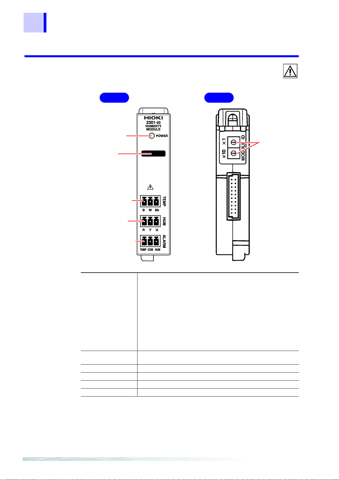
12
Front
Back
TEMP terminal
Module ID
setting dial
ALARM terminal
HUM terminal
Mark area
POWER LED
1 2301-20 HUMIDITY MODULE
1.1.3 Name and Function of the Parts
POWER LED Goes on or flashes when power is supplied to the module.
Remains on, flashe s, or chan ges to another color accordi ng to
the state of the module.
POWER LED indication
Lit in green : Data being recorded.
Flashing in green : Standing by.
Lit in yellow : Alarm output.
Flashing in yellow: Overrange detected.
Lit in red : Non-recoverable error occurred.
Flashing in red : Recoverable error occurred.
Mark area Use this area to make a note of the object to measure or the module ID.
TEMP terminal Connect the temperature sensor to this terminal.
HUM terminal Connect the humidity sensor to this terminal.
ALARM terminal Connect the alarm output cable to this terminal.
Module ID setting dial Use the dial to set the module's identification No.
Use an ink pen, since pencil lead may rub off.
*1
*2
*1: The module needs r e pai r . Co ntact your dealer or H ioki r ep res en tative .
*2: The same module ID may be used by another module.
Page 26
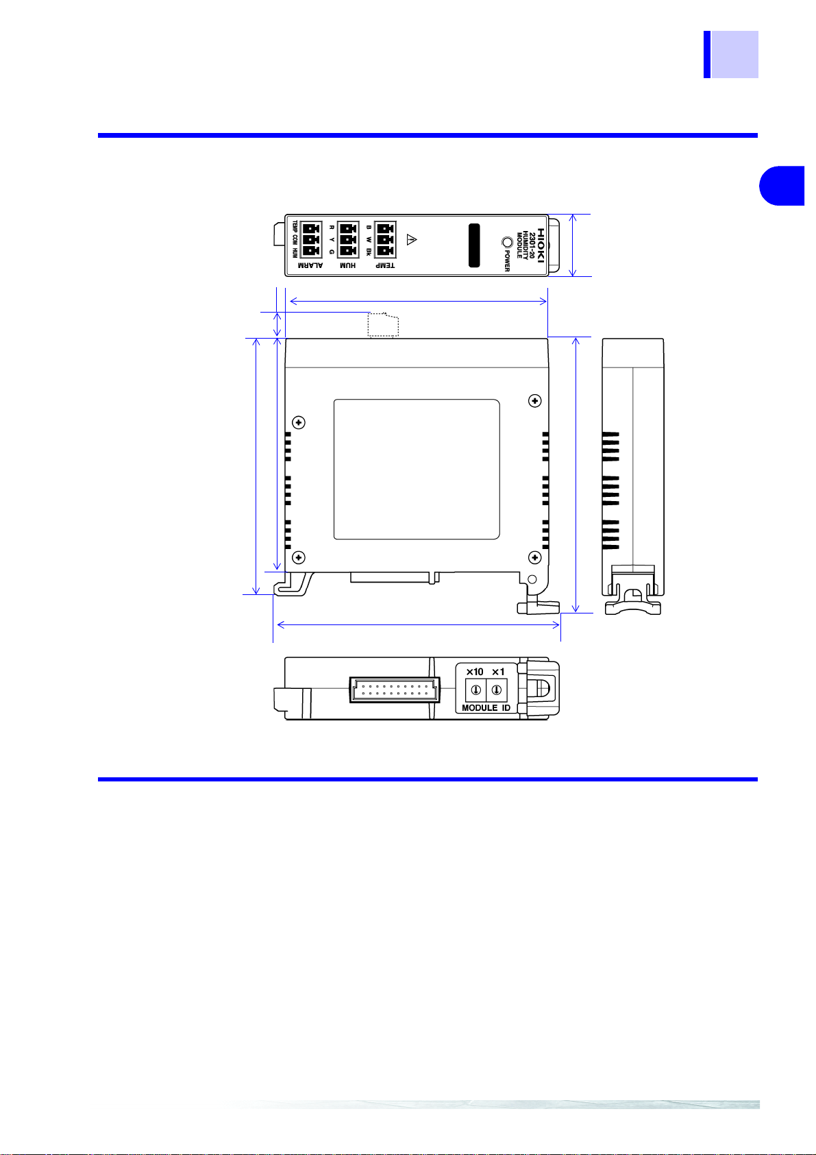
1.1.4 Dimension Diagrams
22.5±1
96±1
9.6±0.5
93.8±1
85±1
103.9±1
100.5±1
(Unit: mm)
13
1 2301-20 HUMIDITY MODULE
1
2
3
4
5
6
7
8
9
1.1.5 Accessory and Option
Accessories
Ferrite clamp ................................................................................. 1
Terminal block ............................................................................... 3
Option
9764-50 HUMIDIDTY SENSOR
APPX
IDX
Page 27

14
1 2301-20 HUMIDITY MODULE
1.2 Settings
1.2.1 Setting the Module ID
You can connect up to 63 measurement modules to one communications module.
Setting Proced u re
Use the module ID setting dial to set the ID No. of the module to a
number from 01 and to 63. (You cannot set a number other than
the above.)
• Ensure that the set ID is not used for any other module connected to the same communications module.
• The ID numbers of modules need not be consecutive.
• Setting the ID to 99, then turning on the power resets all internal settings to the defaults.
• The module ID and COM ID are not related and can be set
independently.
Page 28
1.3 Preparations
1
2
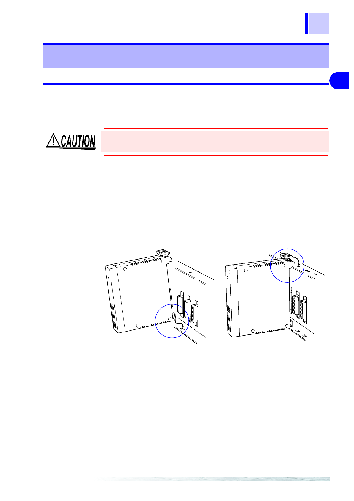
1.3.1 Installing the Module
15
1 2301-20 HUMIDITY MODULE
1
(1) Installing the Module Base
Do not mount the module base on the ceiling where it may fall off.
Fasten the module base to a DIN rail or the wall a ccording to the
procedure described in the
BASE"(P.305) or 20 "2392-01/02 MODULE BASE"(P.319) series
MODULE BASE instruction manual.
(2) Mounting a Module on the Module Base
Mount a module on the module base as shown below. Ensure that
the lever clicks.
19 "2391-01, 23 91-0 2, 239 1-03 MODU LE
2
3
4
5
6
7
8
9
APPX
IDX
Page 29
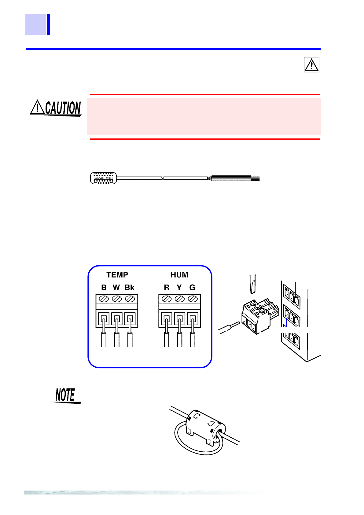
16
Blue RedBlack Green
White Yellow
Sensor cable of the 9764-50
Terminal block
TEMP terminal
HUM terminal
1 2301-20 HUMIDITY MODULE
1.3.2 Connecting Input/Output Cables
(1) Connecting Sensor Cables to the Terminal Block
• The TEMP terminal and HUM terminal are not insulated from
each other. Avoid short-circuiting.
• Be sure to connect the cables to matching connectors to prevent
damage to the module or sensor.
Connect the 9764-50 HUMIDIDTY SENSOR to the module by following the procedure below.
1. Use a flat blade screwdriver to loosen the screws on the t ermi-
nal block.
2. Insert a cable into the terminal block, then tighten the screws
(at a tightening torque of 0.25 N•m).
3.
Connect the terminal block to the TEMP terminal, and HUM terminal.
• In case of external noise, wind the cable around the ferrite
clamp supplied as an accessory as shown below.
• Note that measurement may be adversely affected by external
noise or the electromagnetic environment when using a cable
longer than 3 meters.
Page 30
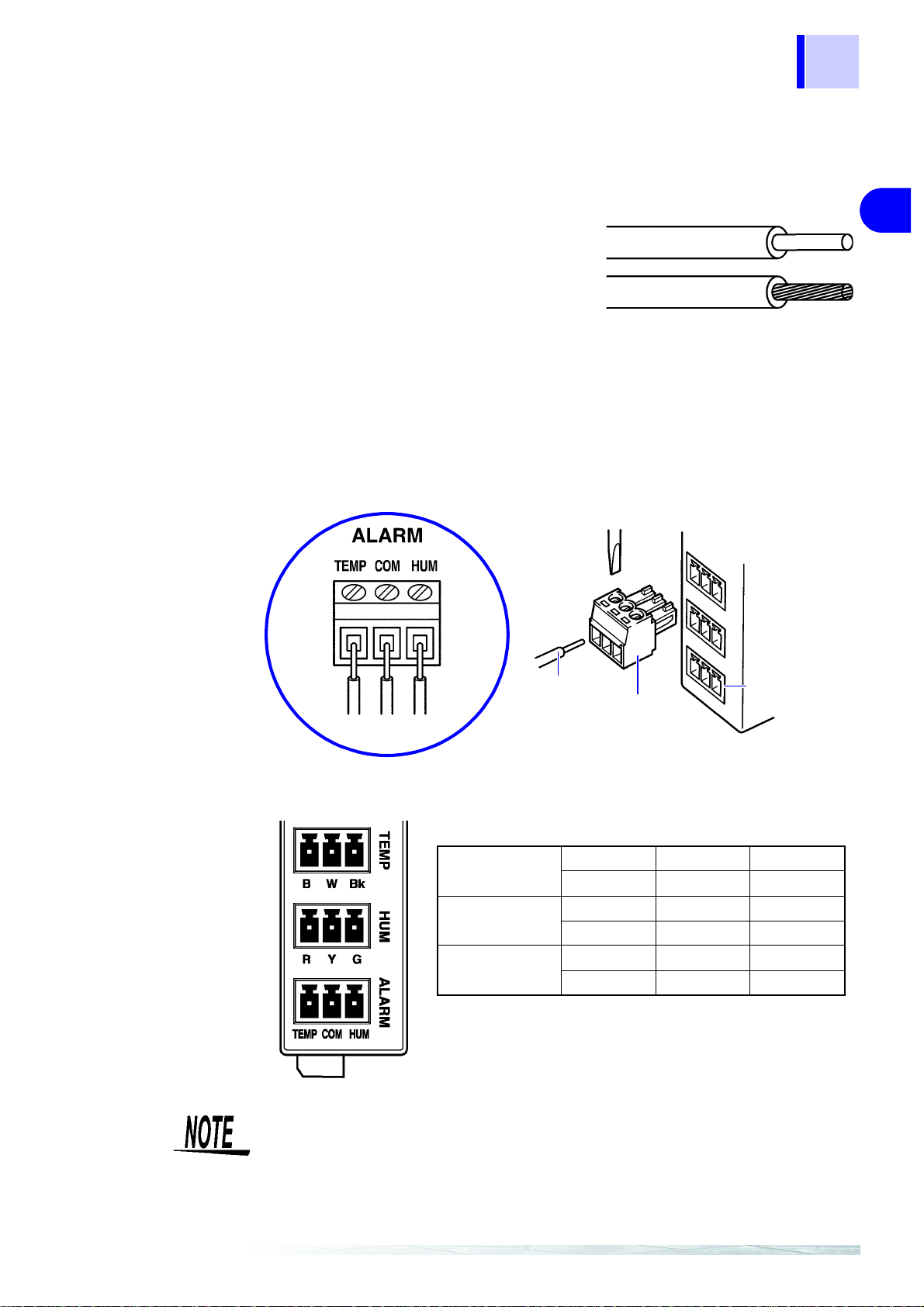
1 2301-20 HUMIDITY MODULE
Single-wire : 0.14 to 1.5 mm
2
Stranded-wire : 0.14 to 1.5 mm
2
AWG : 26 to 16
Cable strip length : 5 mm (0.2")
Terminal block
Terminal block
Cable
ALARM
terminal
TEMP terminal
(Input)
BWBk
Blue White Black
HUM terminal
(Input)
RYG
Red Yellow Green
ALARM terminal
(output)
TEMP COM HUM
Alarm output Common Alarm output
(2) Connecting Cables to the ALARM Terminal (Alarm output)
Recommended Cable
1. Use a flat blade scre wdriver to loosen the screws on the termi-
17
1
2
nal block.
2. Insert a cable for alarm output into the terminal block, then
tighten the screws (at a tightening torque of 0.25 N•m).
3. Connect the ter minal block to the ALARM terminal.
(3) The Location of the Input/Output Cable
3
4
5
6
7
8
The TEMP and HUM terminals are used to connect the optional
9764-50 HUMIDIDTY SENSOR.
9
APPX
IDX
Page 31

18
1 2301-20 HUMIDITY MODULE
9764-50 HUMIDIDTY SENSOR
• To avoid damaging the 2301-20, only connect the 9764-50
HUMIDIDTY SENSOR to the TEMP an d HUM terminals. Moreover, do not input other signals to these terminals.
• If the sensor is used or stored outside the operatin g or storage
ranges, sensor accuracy may be adversely affected and you
may not get accurate measurements even within the one-year
guaranteed period of accuracy.
• Hioki is not liable for any problems caused by sensor use or storage outside the operating or storage ranges.
• When not using th e 9764-50 HUMIDIDTY SEN SOR, seal it in a
plastic bag and store it in a cool, dark place.
• Be careful to avoid condensation on the sensor. If condensation occurs,
you may not get accurate measurements. Condensation is likely to
occur when the sensor is subject to rapid changes in temperature.
Page 32

1.4 Others
TEMP
Photocoupler
<Internal circuit>
COM
HUM
1.4.1 Alarm output
Ensure that the input does not exceed the maximum input
voltage or current to avoid module damage, short-circuiting
and electric shock resulting from heat building.
Output method Open collector
Maximum input voltage / current 30 V, 20 mA max.
Signal logic Enabled: ON Disabled: OFF
19
1 2301-20 HUMIDITY MODULE
1
2
3
4
(1) Internal Circuit
The alarm output circuit is configured as shown below.
• Signal logic indicates the signal state in which a signal's function is enabled.
• The output transistor works as a switch between signal output
and ground in the module. When output becomes enabled, the
switch is turned on and current flows from the output signal to
COM in the module. Therefore, a relay or LED lamp can be
connected directly to the output terminal (P.20).
5
6
7
8
9
APPX
IDX
Page 33

20
<Circuit diagram>
COM
Power
Output
Limit resistor
LED
Connecting LED
Power
Relay
Diode
COM
Output
Connecting relay
TEMP
Wired-OR output
COM
HUM
Using on Wired-OR Logic
1 2301-20 HUMIDITY MODULE
• When connecting a relay or LED lamp, ensure that the relay or
• Open collector output operates on wired-OR logic by short-cir-
lamp operates at up to 30 V and 20 mA. When connecting a
relay, be sure to use a diode to absorb counter electromo tive
force.
cuiting TEMP and HUM. Moreover, it enables the signal if an
alarm occurs in either channel.
Page 34

1 2301-20 HUMIDITY MODULE
Analog
circuit
TEMP/HUM
Measurement
Input
Digital
circuit
Insulating
circuit
Module-to-
module com-
munications
circuit
CAN bus
Connector
Module base
Power
Insulation
withstand voltage
of 1.4 kVAC
Insulation
withstand voltage
of 1.4 kVAC
ALARM
Alarm output
Ground
1.4.2 Insulation of Internal Circuit
In the 2301-20, the input circuit and alarm output are insulated
from the CAN bus as shown in the block diagram below. (Withstand voltage: 1.4 kVAC, 50/60 Hz, Response current: 5 mA, 1
minute)
21
1
2
3
4
The COM terminal of the alarm output terminal is used for both
TEMP and HUM.
5
6
7
8
9
APPX
IDX
Page 35

22
Relative humidity (%RH)
Temperature (°C)
*Accuracy not guaranteed
(reference values)
1 2301-20 HUMIDITY MODULE
1.5 Specifications
1.5.1 Basic Specifications
Sensor type 9764-50 HUMIDIDTY SENSOR
Number of inputs Temperature 1 CH + Humidity 1 CH
Measurement range -40.0 to 85.0°C Resolution: 0.1°C, 0.0 to 100.0%RH Resolution: 0.1%RH
Measurement accuracy Temperature
(Display range: -10.0 to 110.0%RH)
-40.0 to -0.1°C ±1.0°C
0.0 to 35.0°C ±0.5°C
35.1 to 70.0°C ±1.0°C
70.1 to 85.0°C ±2.0°C
Humidity
Period of guaranteed
accuracy
Sampling 1 time / sec.
Input terminal 3 Input terminal block × 2
1 year
1.5.2 Function Specifications
Execute the functions from the PC application via communications.
Monitoring function
This function outputs the current measured values (instantaneous values).
Measured value recording function
Measurements are recorded at a set recording interval.
Real-time manage-
ment
Recording start Immediate start/Reserved-tim e start
Recording end Manual end/Reserved-time end
Operation when
memory is full
Recording interval 1/2/5/10/15/20/30 sec., 1/2/5/10/15/20/30/60 min.
This is automatically set from the PC application at the start of recording.
Memory full stop /Endless
Set the condition before the start of recording.
Page 36

23
1 2301-20 HUMIDITY MODULE
Recording mode • Instantaneous value
• MAX/MIN/AVE
• Instantaneous value + MAX/MIN/AVE
Total 3 modes
Set the mode before the start of recording.
Recorded data One data set contains time and temperature/humidity information (One channel each).
Data is scaled if scaling is ON.
Recording capacity 512 k bytes Flash memory
Quantity of recorded
data
Power outage
protection
Alarm judgment and recording function
Alarm judgment is made at every sampling, and the history will be recorded in flash memory if the measured
value recording function remains active.
Judgment method Criterion threshold can be set to either Hi or Lo.
Recorded data One data set contains time, generation/reversion, CH and judgment threshold.
Alarm output Alarm output × 2 CH
• Instantaneous value recording mode: 30,000 data × 2 CH
• MAX/MIN/AVE recording mode: 15,000 data × 2 CH
• Instantaneous value + MAX/MIN/AVE recording mode: 12,000 data × 2 CH
After recovering from a power outage, the instrument automatically returns to the state
held before the outage.
The instantaneous va lue at every sampli ng is judged (effecti ve in any measurem ent
mode).
Output is turned ON when an alarm (Hi or Lo) occurs.
Whether to hold the al arm output can be selecte d. The reset s witch or a c ommand
can be used to reset alarms.
1
2
3
4
5
1.5.3 General Specifications
Clock accuracy ±100 ppm (Reference value at temperature from 0 to 50°C (32 to 122
communicatio ns mod ule)
Backup Recorded data (saved in flash memory)
Data loss for up to 2 minutes before and after a power outage may occur.
Communication
interface
Maximum rated
voltage to earth
Alarm output Open collector: 30 VDC, 20 mA max.
Rated supply voltage 5 V±0.3 VDC
Maximum rated Power
Dielectric strength 1.4 kVAC Between input and alarm output, Input/Output and CAN bus (50/60 Hz,
Dimensions Approx. 22.5W × 96H × 85D mm (0.89"W × 3.78"H × 3.35"D) (excluding projections)
Mass Approx. 120 g (4.2 oz.)
Accessories Ferrite clamp............. ...... ....... ...... ....... ...... ...... ....... ...... ....... ...... ....... ...... ......................1
Option 9764-50 HUMIDIDTY SENSOR
Operational ranges
for temperature and
humidity
Temperature and
humidity ranges for
storage
Operating
environment
Standards applying Safety EN61010, Pollution degree 2, Measurement Category I
CAN bus
33 Vrms, 70 VDC
1.4 W
Response current 5 mA, one minutes
Terminal block.............................. ....... ...... ...... .............................................. ...... ....... .. 3
0 to 50°C (32 to 122
-10 to 50°C (14 to 122
Indoors, altitude up to 2000 m (6562-ft.)
(anticipated transient overvoltage 330 V)
EMC EN61326, CLASS A
°F)
, 80%RH or less (with no condensation)
°F)
, 80%RH or less (with no condensation)
°F)
without the
6
7
8
9
APPX
IDX
Page 37

24
1 2301-20 HUMIDITY MODULE
1.5.4 9764-50 HUMIDIDTY SENSOR Specifications
Operational ranges
for temperature and
humidity
Temperature and
humidity ranges for
storage
Response time Temperature: Approx. 100 sec., Humidity: Approx.300 sec.
Temperature sensor Thermistor
Humidity sensor High polymer film (capacitive humidity sensor)
Cord length Approx. 3 m
Dimensions Sensor, Approx. 30W × 13H × 8D mm (1.18" W × 0.51"H × 0.31"D)
Long time stability ±1%RH (5 years at 25°C (77
-40 to 85°C (-40 to 185
-40 to 85°C (-40 to 185
°F)
, 0.0 to 100.0%RH (with no condensation)
°F)
, 0.0 to 100.0%RH (with no condensation)
°F)
, 50%RH, reference value)
The 2301-20 may indicate a humidity measurement below z ero or
above 100%RH. These values indicate a change in low or high
humidity levels, and do not indicate ac tual humidity (since values
over 100% and lower than 0% are impossible).
Page 38

2 2302-20 Pt MODULE
(Conceptual image)
2302-20 Pt MODULE 2
2.1 Overview
25
1
2
2.1.1 Product Overview
• The 2302-20 is a measurement module of Hioki "Smart Site"
(remote measurement system).
• This module measures and records temperature at regular intervals.
• The 2302-20 is used with the power supply module, communications module, and module base.
Usable Temperature sensor Platinum resistance thermometer sensor
Number of measurement channels Temperature 2 CH
Measurement range -100.0 to 300.0°C
(Selectable between Pt100 and JPt100)
3
4
5
6
7
8
2.1.2 Majo r Fe atures
The recordin g interval is selectable from 1 secon d to
60 minutes.
The maximum, minimum, and average measurements
during the recording interval can be recorded (with
sampling once a second).
The module has an alarm output terminal.
Rough Estimate of Storable Data Quantity and Time.
9
APPX
IDX
Page 39

26
2 2302-20 Pt MODULE
Action at memory full: Continue recording (Endless)
Quantity of
storable data
Recording interval
1 sec. 7.5 hours 3.5 hours 2.5 hours
2 sec. 14.5 hours 7 hours 5.5 hours
5 sec. 1.5 days 18 hours 14.5 hours
10 sec. 3 days 1.5 days 1 day
15 sec. 4.5 days 2 days 1.5 days
20 sec. 6 days 3 days 2 days
30 sec. 9 days 4.5 days 3.5 days
1 min. 18 days 9 days 7 days
2 min. 36 days 18 days 14 days
5 min. 92 days 46 days 36 days
10 min. 184 days 92 days 73 days
15 min. 277 days 138 days 110 days
20 min. 369 days 184 days 147 days
30 min. 554 days 277 days 221 days
60 min. 1109 days 554 days 443 days
Recording Mode
Instantaneous
Value
26000 13000 10000
MAX/MIN/AVE Instantaneous V alue
+ MAX/MIN/A VE
When the alarm log is ON, the higher the number of alarms generated, the smaller the recording period. (A pprox. 1 of the data
per alarm)
Page 40

2 2302-20 Pt MODULE
Action at memory full: Stop recording (Memory full stop)
Recording Mode
Instantaneous
Value
Quantity of
storable data
Recording interval
1 sec. 8.5 hours 4 hours 3 hours
2 sec. 17 hours 8.5 hours 6.5 hours
5 sec. 1.5 days 21 hours 17 hours
10 sec. 3.5 days 1.5 days 1.5 days
15 sec. 5 days 2.5 days 2 days
20 sec. 7 days 3.5 days 2.5 days
30 sec. 10 days 5 days 4 days
1 min. 21 days 10 days 8 days
2 min. 42 days 21 days 17 days
5 min. 106 days 53 days 42 days
10 min. 213 days 106 days 85 days
15 min. 319 days 159 days 127 days
20 min. 426 days 213 days 170 days
30 min. 639 days 319 days 255 days
60 min. 1279 days 639 days 511 days
30000 15000 12000
MAX/MIN/AVE Instantaneous Value
27
+ MAX/MIN/A VE
1
2
3
4
5
6
When the alarm log is ON, the higher the number of alarms generated, the smaller the recording period. (Approx. 1 of the data
per alarm)
7
8
9
APPX
IDX
Page 41

28
Front
Back
CH1 terminal
Module ID
setting dial
ALARM terminal
CH2 terminal
Mark area
POWER LED
2 2302-20 Pt MODULE
2.1.3 Name and Function of the Parts
POWER LED Goes on or flashes when power is supplied to the module.
Mark area Use this area to make a note of the object to measure or the
CH1 terminal Connect the platinum resistance thermometer sensor to this
CH2 terminal Connect the platinum resistance thermometer sensor to this
ALARM terminal Connect the alarm output cable to this terminal. This terminal is
Module ID setting dial Use the dial to set the module's identification No.
Remains on, flashe s, or chan ges to another color accordi ng to
the state of the module.
POWER LED indication
Lit in green : Data being recorded.
Flashing in green : Standing by.
Lit in yellow : Alarm output.
Flashing in yellow: Overrange detected.
Lit in red : Non-recoverable error occurred.
Flashing in red: Recoverable error occurred.
module ID.
Use an ink pen, since pencil lead may rub off.
*2
*1
terminal. (Channel 1)
terminal. (Channel 2)
electrically insulated from the CH1 and CH2 terminals.
*1: The module needs r e pai r . Co ntact your dealer or H ioki r ep res en tative .
*2: The same mod ule ID may be used by a nother module .
Page 42

2.1.4 Dimension Diagrams
22.5±1
96±1
9.6±0.5
93.8±1
85±1
103.9±1
100.5±1
(Unit: mm)
29
2 2302-20 Pt MODULE
1
2
3
4
5
6
7
2.1.5 Accessory and Option
Accessories
Ferrite clamp ................................................................................. 2
Terminal block ............................................................................... 3
Option
None
8
9
APPX
IDX
Page 43

30
2 2302-20 Pt MODULE
2.2 Settings
2.2.1 Setting the Module ID
You can connect up to 63 measurement modules to one communications module.
Setting Proced u re
Use the module ID setting dial to set the ID No. of the module to a
number from 01 and to 63. (You cannot set a number other than
the above.)
• Ensure that the set ID is not used for any other module connected to the same communications module.
• The ID numbers of modules need not be consecutive.
• Setting the ID to 99, then turning on the power resets all internal settings to the defaults.
• The module ID and COM ID are not related and can be set
independently.
Page 44

2.3 Preparations
1
2
Single-wire : 0.14 to 1.5 mm
2
Stranded-wire : 0.14 to 1.5 mm
2
AWG : 26 to 16
Cable strip length : 5 mm (0.2")
2.3.1 Installing the Module
31
2 2302-20 Pt MODULE
1
(1) Installing the Module Base
Do not mount the module base on the ceiling where it may fall off.
Fasten the module base to a DIN rail or the wall a ccording to the
procedure described in the
BASE"(P.305) or 20 "2392-01/02 MODULE BASE"(P.319) series
MODULE BASE instruction manual.
(2) Mounting a Module on the Module Base
Mount a module on the module base as shown below. Ensure that
the lever clicks.
19 "2391-01, 23 91-0 2, 239 1-03 MODU LE
2
3
4
5
6
7
2.3.2 Connecting Input/Output Cables
Recommended Cable
8
9
APPX
IDX
Page 45

32
CH2 terminal
CH1 terminal
Terminal block
Terminal block
Cable
2 2302-20 Pt MODULE
(1) Connecting Cables to the CH1 and CH2 Terminals
(Temperature Sensor Signal Input)
The CH1 and CH2 terminals are not insulated from each other. Avoid
short-circuiting.
1. Use a flat blade screwdriver to loosen the screws on the t ermi-
nal block.
2. Insert a cable for input temperature sensor signal into the ter-
minal block, then tighten the screws (at a tightening torque of
0.25 N•m).
3. Connect the terminal block to the CH1 or CH2 terminal.
• The CH1 and CH2 terminals are not insulated from each other.
When measuring two measurement points having a potential
difference, use an electrically insulated sensor or another Pt
module, since measurements may be adversely affected.
• In case of external noise, wind the cable around the ferrite
clamp supplied as an accessory as shown below.
• Note that measurement may be adversely affected by external
noise or the electromagnetic environment when using a cable
longer than 3 meters.
Page 46

2 2302-20 Pt MODULE
Terminal block
Terminal block
Cable
ALARM terminal
Connect the cable for CH1 output to CH1 and COM; and
connect the cable for CH2 output to CH2 and COM.
CH1
terminal
(Input)
Left Center Right
Resistance
thermome-
ter sensor
input (A)
Resistance
thermome-
ter sensor
input (B)
Conductor
input (B)
CH2
terminal
(Input)
Left Center Right
Resistance
thermome-
ter sensor
input (A)
Resistance
thermome-
ter sensor
input (B)
Conductor
input (B)
ALARM
terminal
(output)
CH1 COM CH2
Alarm
output
Common
Alarm
output
(2) Connecting Cables to the ALARM Terminal (Alarm output)
1. Use a flat blade scre wdriver to loosen the screws on the termi-
nal block.
33
2. Insert a cable for alarm output into the terminal block, then
tighten the screws (at a tightening torque of 0.25 N•m).
3. Connect the ter minal block to the ALARM terminal.
(3) The Location of the Input/Output Cable
1
2
3
4
5
6
Temperature Sensor
Only connect the Pt100 or JPt100 sensor to the CH1 and CH2
terminals to avoid damaging the 2302-20. Moreover, do not
input other signals to these terminals.
7
8
9
APPX
IDX
Page 47

34
CH1
Photocoupler
<Internal circuit>
COM
CH2
2 2302-20 Pt MODULE
2.4 Others
2.4.1 Alarm output
(1) Output Rating
Ensure that the input does not exceed the maximum input
voltage or current to avoid module damage, short-circuiting
and electric shock resulting from heat building.
Output method Open collector
Maximum input voltage / current 30 V, 20 mA max.
Signal logic Enabled: ON Disabled: OFF
(1) Internal Circuit
The alarm output circuit is configured as shown below.
• Signal logic indicates the signal state in which a signal's function is enabled.
• The output transistor works as a switch between signal output
and ground in the module. When output becomes enabled, the
switch is turned on and current flows from the output sign al to
COM in the module. Therefore, a relay or LED lamp can be
connected directly to the output terminal (P.35).
Page 48

2 2302-20 Pt MODULE
<Circuit diagram>
COM
Power
Output
Limit resistor
LED
Connecting LED
Power
Relay
Diode
COM
Output
Connecting relay
CH1
Wired-OR output
COM
CH2
Using on Wired-OR Logic
35
1
2
3
4
• When connecting a relay or LED lamp, ensure that the relay or
lamp operates at up to 30 V and 20 mA. When connecting a
relay, be sure to use a diode to absorb counter electromotive
force.
• Open collector output operates on wired-OR logic by short-circuiting CH1 and CH2. Moreover, it enables the signal if an
alarm occurs in either channel.
5
6
7
8
9
APPX
IDX
Page 49

36
Analog
circuit
CH1/ CH2
Measurement
Input
Digital
circuit
Insulating
circuit
Module-to-
module com-
munications
circuit
CAN bus
Connector
Module base
Power
Insulation
withstand voltage
of 1.4 kVAC
Insulation
withstand voltage
of 1.4 kVAC
ALARM
Alarm output
Ground
2 2302-20 Pt MODULE
2.4.2 Insulation of Internal Circuit
The CH1 and CH2 terminals are not insulated from each other.
When connecting signals different in potential to these terminals, use
an additional measurement module or insulate the signals externally
before connection to the terminals. Th is will pr event module er rors and
malfunction.
In the 2302-20, the input circuit and alarm output are insulated
from the CAN bus as shown in the block diagram below. (Withstand voltage: 1.4 kVAC, 50/60 Hz, Response current: 5 mA, 1
minute)
The COM terminal of the alarm output terminal is u sed for both
CH1 and CH2.
Page 50

2.5 Specifications
2.5.1 Basic Specifications
37
2 2302-20 Pt MODULE
1
Sensor type Platinum resistance thermometer sensor
Number of inputs 2 CH
Measurement current 0.5 mA
Measurement range -100.0 to 300.0°C, Resolution: 0.1°C
Measurement accuracy
Influence of radiated
radio-frequency
electromagnetic field
Period of guaranteed
accuracy
Sampling 1 time / sec.
Input terminal 3 Input terminal block × 2
Pt100 (3-wire sensor) / JPt100 (3-wire sensor, JIS C 1604-1997)
±0.1%rdg.±0.4°C
±2°C at 10 V/m
1 year
2.5.2 Functio n Specificat io ns
Execute the functions from the PC application via communications.
Monitoring function
This function outputs the current measured values (instantaneous values).
2
3
4
5
6
7
Measured value recording function
Measurements are recorded at a set recording interval.
Real-time manage-
ment
Recording Start Immediate start/Reserved-time start
Recording End Manual end/Reserved-time end
Operation when
memory is full
Recording interval 1/2/5/10/15/20/30 sec., 1/2/5/10/15/20/30/60 min.
Recording mode • Instantaneous value
Recorded data One data set contains time and temperature/humidity information (Two channel each).
Recording capacity 512 k bytes Flash memory
Quantity of recorded
data
Power outage
protection
This is automatically set from the PC application at the start of recording.
Memory full stop /Endless
Set the condition before the start of recording.
• MAX/MIN/AVE
• Instantaneous value + MAX/MIN/AVE
Total 3 modes
Set the mode before the start of recording.
Data is scaled if scaling is ON.
• Instantaneous value recording mode: 30,000 data × 2 CH
• MAX/MIN/AVE recording mode: 15,000 data × 2 CH
• Instantaneous value + MAX/MIN/AVE recording mode: 12,000 data × 2 CH
After recovering from a power outage, the instrument automatically returns to the state
held before the outage.
8
9
APPX
IDX
Page 51

38
2 2302-20 Pt MODULE
Alarm judgment and recording function
Alarm judgment is made at every sampling, and the history will be recorded in flash memory if the measured
value recording function remains active.
Judgment method Criterion threshold can be set to either Hi or Lo.
Recorded data One data set contains time , generation/reversion, CH and judg ment threshold inforAlarm output A larm output × 2 CH
The instantaneous value at every sampling is judged (effective in a ny measurement
mode).
mation.
Output is turned ON when an alarm (Hi or Lo) occurs.
Whether to hold the alarm outpu t can be sel ected. The r eset switch or a command
can be used to reset alarms.
2.5.3 General Specifications
Clock accuracy ±100 ppm (Reference value at tempera ture from 0 to 50°C ( 32 to 122°F) without the
Backup Recorded data (saved in flash memory)
Communication
interface
Maximum rated
voltage to earth
Alarm output O pen collector: 30 VDC, 20 mA max.
Rated supply voltage 5 V±0.3 VDC
Maximum rated power 1.4 W
Dielectric strength 1.4 kVAC Between input and alarm output, Input/Output and CAN bus (50/60 Hz,
Dimensions Approx. 22.5W × 96H × 85D mm (0.89"W × 3.78"H × 3.35"D) (excluding projections)
Mass Approx. 120 g (4.2 oz.)
Accessories Ferrite clamp................................................................................................................2
Operational ranges
for temperature and
humidity
Temperature and
humidity ranges for
storage
Operating
environment
Standards applying Safety EN61010, Pollution Degree 2, Measurement Category I,
communications module)
Data loss for up to 2 minutes before and after a power outage may occur.
CAN bus
33 Vrms, 70 VDC
Response current 5 mA, one minutes
Terminal block..............................................................................................................3
0 to 50°C (32 to 122°F), 80%RH or less (with no condensation)
-10 to 50°C (14 to 122°F), 80%RH or less (with no condensation)
Indoors, altitude up to 2000 m (6562-ft.)
(anticipated transient overvoltage 330 V),
EMC EN61326, CLASS A
Page 52

3 2303-20 TC MODULE
(Conceptual image)
2303-20 TC MODULE 3
3.1 Overview
39
1
2
3.1.1 Product Overview
• The 2303-20 is a measurement module of Hioki "Smart Site"
(remote measurement system).
• This module measures and records temperature at regular intervals.
• One module can be used for measurement at two locations.
• The 2303-20 is used with the power supply module, communications module, and module base.
Usable Temperature sensor Thermocouple
Number of measurement channels Temperature 2 CH
Measurement range -100.0 to 1600.0°C
3
4
5
(Selectable between K, E, J, T and R)
6
7
8
3.1.2 Majo r Fe atures
The recordin g interval is selectable from 1 secon d to
60 minutes.
The maximum, minimum, and average measurements
during the recording interval can be recorded (with
sampling once a second).
The module has an alarm output terminal.
9
APPX
IDX
Page 53

40
3 2303-20 TC MODULE
Rough Estimate of Storable Data Quantity and Time
Action at memory full: Continue recording (Endless)
Quantity of
storable data
Recording interval
1 sec. 7.5 hours 3.5 hours 2.5 hours
2 sec. 14.5 hours 7 hours 5.5 hours
5 sec. 1.5 days 18 hours 14.5 hours
10 sec. 3 days 1.5 days 1 day
15 sec. 4.5 days 2 days 1.5 days
20 sec. 6 days 3 days 2 days
30 sec. 9 days 4.5 days 3.5 days
1 min. 18 days 9 days 7 days
2 min. 36 days 18 days 14 days
5 min. 92 days 46 days 36 days
10 min. 184 days 92 days 73 days
15 min. 277 days 138 days 110 days
20 min. 369 days 184 days 147 days
30 min. 554 days 277 days 221 days
60 min. 1109 days 554 days 443 days
Recording Mode
Instantaneous
Value
26000 13000 10000
MAX/MIN/AVE Instantaneous V alue
+ MAX/MIN/A VE
When the alarm log is ON, the higher the number of alarms generated, the smaller the recording period. (A pprox. 1 of the data
per alarm)
Page 54

3 2303-20 TC MODULE
Action at memory full: Stop recording (Memory full stop)
Recording Mode
Instantaneous
Value
Quantity of
storable data
Recording interval
1 sec. 8.5 hours 4 hours 3 hours
2 sec. 17 hours 8.5 hours 6.5 hours
5 sec. 1.5 days 21 hours 17 hours
10 sec. 3.5 days 1.5 days 1.5 days
15 sec. 5 days 2.5 days 2 days
20 sec. 7 days 3.5 days 2.5 days
30 sec. 10 days 5 days 4 days
1 min. 21 days 10 days 8 days
2 min. 42 days 21 days 17 days
5 min. 106 days 53 days 42 days
10 min. 213 days 106 days 85 days
15 min. 319 days 159 days 127 days
20 min. 426 days 213 days 170 days
30 min. 639 days 319 days 255 days
60 min. 1279 days 639 days 511 days
30000 15000 12000
MAX/MIN/AVE Instantaneous Value
41
+ MAX/MIN/A VE
1
2
3
4
5
6
When the alarm log is ON, the higher the number of alarms generated, the smaller the recording period. (Approx. 1 of the data
per alarm)
7
8
9
APPX
IDX
Page 55

42
Front
Back
CH1 terminal
Module ID
setting dial
ALARM terminal
CH2 terminal
Mark area
POWER LED
3 2303-20 TC MODULE
3.1.3 Name and Function of the Parts
POWER LED Goes on or flashes when power is supplied to the module.
Mark area Use this area to make a note of the object to measure or the
CH1 terminal Connect a thermocou ple and external RJC (reference junction
CH2 terminal Connect a thermocouple to this terminal (channel 2).
ALARM terminal Connect the alarm output cable to this terminal. This terminal is
Module ID setting dial Use the dial to set the module's identification No.
Remains on, flashe s, or chan ges to another color accordi ng to
the state of the module.
POWER LED indication
Lit in green : Data being recorded.
Flashing in green : Standing by.
Lit in yellow : Alarm output.
Flashing in yellow: Overrange detected.
Lit in red : Non-recoverable error occurred.
Flashing in red : Recoverable error occurred.
module ID.
Use an ink pen, since pencil lead may rub off.
*1
*2
compensation) sensor to this terminal (channel 1).
electrically insulated from the CH1 and CH2 terminals.
*1: The module needs r e pai r . Co ntact your dealer or H ioki r ep res en tative .
*2: The same mod ule ID may be used by a nother module .
Page 56

3.1.4 Dimension Diagrams
22.5±1
96±1
9.6±0.5
93.8±1
85±1
103.9±1
100.5±1
(Unit: mm)
43
3 2303-20 TC MODULE
1
2
3
4
5
6
7
3.1.5 Accessory and Option
Accessories
External RJC (reference junction compensation) sensor.............1
Ferrite clamp ................................................................................2
Terminal block ..............................................................................3
Option
None
8
9
APPX
IDX
Page 57

44
3 2303-20 TC MODULE
3.2 Settings
3.2.1 Setting the Module ID
You can connect up to 63 measurement modules to one communications module.
Setting Proced u re
Use the module ID setting dial to set the ID No. of the module to a
number from 01 and to 63. (You cannot set a number other than
the above.)
• Ensure that the set ID is not used for any other module connected to the same communications module.
• The ID numbers of modules need not be consecutive.
• Setting the ID to 99, then turning on the power resets all internal settings to the defaults.
• The module ID and COM ID are not related and can be set
independently.
Page 58

3.3 Preparations
1
2
Single-wire : 0.14 to 1.5 mm
2
Stranded-wire : 0.14 to 1.5 mm
2
AWG : 26 to 16
Cable strip length : 5 mm (0.2")
3.3.1 Installing the Module
45
3 2303-20 TC MODULE
1
(1) Installing the Module Base
Do not mount the module base on the ceiling where it may fall off.
Fasten the module base to a DIN rail or the wall a ccording to the
procedure described in the
BASE"(P.305) or 20 "2392-01/02 MODULE BASE"(P.319) series
MODULE BASE instruction manual.
(2) Mounting a Module on the Module Base
Mount a module on the module base as shown below. Ensure that
the lever clicks.
19 "2391-01, 23 91-0 2, 239 1-03 MODU LE
2
3
4
5
6
7
3.3.2 Connecting Input/Output Cables
Recommended Cable
8
9
APPX
IDX
Page 59

46
External RJC (reference junction compensation) sensor
CH2 terminal
CH1 terminal
Terminal block
Terminal block
Sensor Cable
3 2303-20 TC MODULE
(1) Connecting Cables to the CH1 and CH2 Terminals
(Thermocouple Signal Input)
• The CH1 and CH2 terminals are not insulated from each other.
Avoid short-circuiting.
• Do not add power to external RJC (reference juncti on compensation) sensor
surement by the sensor’s breaking.
. It becomes impossible to do a correct mea-
1. Use a flat blade screwdriver to loosen the screws on the t ermi-
nal block.
2. Insert an external RJC (reference junction compensation)
sensor into the CH1 terminal.
3. Insert a sensor cable into the terminal block, then tighten the
screws (at a tightening torque of 0.25 N•m).
4. Connect the terminal block to the CH1 or CH2 terminal.
Page 60

47
Terminal block
Terminal block
Cable
ALARM terminal
Connect the cable for CH1 output to CH1 and COM; and
connect the cable for CH2 output to CH2 and COM.
3 2303-20 TC MODULE
• The CH1 and CH2 terminals are not insulated from each other.
Use an electrically insulated sensor or another TC module,
since measurements may be adversely affected.
• In case of external noise, wind the cable around the ferrite
clamp supplied as an accessory as shown below.
1
2
• Note that measurement may be adversely affected by external
noise or the electromagnetic environment when using a cable
longer than 3 meters.
(2) Connecting Cables to the ALARM Terminal (Alarm output)
1. Use a flat blade scre wdriver to loosen the screws on the termi-
nal block.
2. Insert a cable for alarm output into the terminal block, then
tighten the screws (at a tightening torque of 0.25 N•m).
3. Connect the ter minal block to the ALARM terminal.
3
4
5
6
7
8
9
APPX
IDX
Page 61

48
CH 1 terminal
(Input)
+-
Thermocouple input (+)
External
RJC sensor
Thermocouple input (-),
External
RJC sensor
CH 2 terminal
(Input)
+NC-
Thermocouple input (+)
-
Thermocou-
ple input (-)
ALARM terminal
(output)
CH1 COM CH2
Alarm output Commo n Al arm outp ut
3 2303-20 TC MODULE
(3) The Location of the Input/Output Cable
Temperature Sensor
Only connect the K, E, J, T or R thermocouple sensor, or the sensor
supplied for extern al RJC (reference junction compens ation) sensor to
the CH1 and CH2 terminals to avoid damaging the 2303-20. Moreover,
do not input other signals to these terminals.
Page 62

3.4 Others
CH1
Photocoupler
<Internal circuit>
COM
CH2
3.4.1 Alarm output
49
3 2303-20 TC MODULE
1
(1) Output Rating
Ensure that the input does not exceed the maximum input
voltage or current to avoid module damage, short-circuiting
and electric shock resulting from heat building.
Output method Open collector
Maximum input voltage / current 30 V, 20 mA max.
Signal logic Enabled: ON Disabled: OFF
(2) Internal Circuit
The alarm output circuit is configured as shown below.
2
3
4
5
6
7
• Signal logic indicates the signal state in which a signal's function is enabled.
• The output transistor works as a switch between signal output
and ground in the module. When output becomes enabled, the
switch is turned on and current flows from the output signal to
COM in the module. Therefore, a relay or LED lamp can be
connected directly to the output terminal (P.50).
8
9
APPX
IDX
Page 63

50
<Circuit diagram>
COM
Power
Output
Limit resistor
LED
Connecting LED
Power
Relay
Diode
COM
Output
Connecting relay
CH1
Wired-OR output
COM
CH2
Using on Wired-OR Logic
3 2303-20 TC MODULE
• When connecting a relay or LED lamp, ensure that the relay or
• Open collector output operates on wired-OR logic by short-cir-
lamp operates at up to 30 V and 20 mA. When connecting a
relay, be sure to use a diode to absorb counter electromo tive
force.
cuiting CH1 and CH2. Moreover, it enables the signal if an
alarm occurs in either channel.
Page 64

3.4.2 Insulation of Internal Circuit
Analog
circuit
CH1/ CH2
Measurement
Input
Digital
circuit
Insulating
circuit
Module-to-
module com-
munications
circuit
CAN bus
Connector
Module base
Power
Insulation
withstand voltage
of 1.4 kVAC
Insulation
withstand voltage
of 1.4 kVAC
ALARM
Alarm output
Ground
The CH1 and CH2 terminals are not insulated from each other.
When connecting signals different in potential to these terminals, use
an additional measurement module or insulate the signals externally
before connection to the terminals. This will prevent module errors and
malfunction.
51
3 2303-20 TC MODULE
1
2
In the 2303-20, the input circuit and alarm output are insulated
from the CAN bus as shown in the block diagram below. (Withstand voltage: 1.4 kVAC, 50/60 Hz, Response current: 5 mA, 1
minute)
The COM terminal of the alarm output terminal is used for both
CH1 and CH2.
3
4
5
6
7
8
9
APPX
IDX
Page 65

52
3 2303-20 TC MODULE
3.5 Specifications
3.5.1 Basic Specifications
Sensor type Thermocouple (K, E, J, T, R)
Number of inputs 2 CH
Reference junction
compensation
accuracy
Temperature of
guaranteed accuracy
Warm-up time 1 hour
Period of guaranteed
accuracy
Sampling 1 time / sec.
Input terminal 3 Input terminal block × 2
±2.0°C (Reference junction compensation range: 0 to 50°C (32 to 122°F)
Pt. allowance:±0.2%rdg. (including ±0.5°C)
23±5°C (73±8.5°F) (Module temperature)
1 year
Others measurement function
Thermocouple type
Measurement range(°C) -100.0 to 1000.0°C -100.0 to 400.0°C 0.0 to 1600.0°C
Measurement resolution(°C)
Measurement accuracy(°C)
Temperature coefficient(°C/°C) ±0.05°C ±0.3°C
Influence of radiated
radio-frequency
electromagnetic field(°C)
Module measurement accuracy is including RJC accuracy.
•
•
This applies w hen inserting an external RJC in to pins center and right terminal s of
.
CH1
•
Temperature coefficient is added from 0 to 18°C, 28 to 50°C (32 to 64°F, 82 to
122°F) to the measurement accuracy.
K, E, J T R
0.1°C
±0.1%f.s.±2.0°C
±10°C ±60°C
0.3°C (to 100)
0.2°C (to 1000)
0.1°C (to 1600)
±6°C (to 100)
±4°C (to 1000)
±2.5°C (to 1600)
•Influence of radiated radio- frequen cy ele ctromagn etic field shows the am ount of the
influence in 10 V/m.
Page 66

3 2303-20 TC MODULE
3.5.2 Functio n Specificat io ns
Execute the functions from the PC application via communications.
53
Monitoring function
This function outputs the current measured values (instantaneous values).
Measured value recording function
Measurements are recorded at a set recording interval.
Real-time manage-
ment
Recording start Immediate start/Reserved-time start
Recording end Manual end/Reserved-time end
Operation when
memory is full
Recording interval 1/2/5/10/15/20/30 sec., 1/2/5/10/15/20/30/60 min.
Recording mode • Instantaneous value
Recorded data One data set contains time and temperature/humidity information (2 channel each).
Recording capacity 512 k bytes Flash memory
Quantity of recorded
data
Power outage
protection
This is automatically set from the PC application at the start of recording.
Memory full stop /Endless
Set the condition before the start of recording.
• MAX/MIN/AVE
• Instantaneous value + MAX/MIN/AVE
Total 3 modes
Set the mode before the start of recording.
Data is scaled if scaling is ON.
• Instantaneous value recording mode: 30,000 data × 2 CH
• MAX/MIN/AVE recording mode: 15,000 data × 2 CH
• Instantaneous value + MAX/MIN/AVE recording mode: 12,000 data × 2 CH
After recovering from a power outage, the instrument automatically returns to the state
held before the outage.
1
2
3
4
5
6
Alarm judgment and recording function
Alarm judgment is made at every sampling, and the history will be recorded in flash memory if the measured
value recording function remains active.
Judgment method Criterion threshold can be set to either Hi or Lo.
The instantaneous value at every sampling is judged (effective in any measurement mode).
Recorded data One data set contains time, generati on/reversion, CH and judgment thre shold infor-
mation.
3.5.3 General Specifications
Clock accuracy ±100 ppm (Reference value at temp erature from 0 to 50°C (32 to 1 22°F) without the
Backup Recorded data (saved in flash memory)
Communication
interface
Maximum rated voltage
to earth
Alarm output Open collector: 30 VDC, 20 mA max.
Rated supply voltage 5 V±0.3 VDC
Maximum rated pow er 1.4 W
Dielectric strength 1.4 kVAC Between input and alarm output, Input/Output and CAN bus (50/60 Hz,
communicatio ns mod ule)
Data loss for up to 2 minutes before and after a power outage may occur.
CAN bus
33 Vrms, 70 VDC (Total of input voltage)
Response current 5 mA, one minutes).
7
8
9
APPX
IDX
Page 67

54
3 2303-20 TC MODULE
Dimensions Approx. 22.5W × 96H × 85D mm (0.89"W × 3.78"H × 3.35"D) (excluding projections)
Mass Approx. 120 g (4.2 oz.)
Accessories Ferrite clamp.....................................................................................................2
Operational ranges
for temperature and
humidity
Temperature and
humidity ranges for
storage
Operating
environment
Standards applying Safety EN61010, Pollution Degree 2, Measurement Category I,
External RJC (reference junction compensation) sensor .................................1
Terminal block...................................................................................................3
0 to 50°C (32 to 122°F), 80%RH or less (with no condensation)
-10 to 50°C (14 to 122°F), 80%RH or less (with no condensation)
Indoors, altitude up to 2000 m (6562-ft.)
(anticipated transient overvoltage 330 V)
EMC EN61326, CLASS A
Page 68

4 2304-20 PULSE MODULE
(Conceptual image)
2304-20 PULSE MODULE 4
4.1 Overview
55
1
2
4.1.1 Product Overview
• The 2304-20 is a measurement module of the Hio ki "Smart S ite"
(remote measurement system).
• This module measures and records current pulses, voltage
pulses and no-voltage contact output at regular intervals. For
example, the 2304-20 can be used to measure pulse output from
a watthour meter or flowmeter.
• The 2304-20 is used with the power supply module, communications module, and module base.
Usable current sensor 9766 CLAMP ON SENSOR
Number of measurement channels 1channel for voltage/
Measurement range 16,000 k pulse/interval
Input pulse 4 kHz max. (voltage/contact)
contact pulse+1channel for current pulse
40 Hz max. (current)
3
4
5
6
7
8
9
APPX
IDX
Page 69

56
4 2304-20 PULSE MODULE
4.1.2 Major Features
The recording interval is selectable from 1 second to
60 minutes.
The totals of measurements made during a re cording
interval can be recorded (with sampling once a second).
The module has an alarm output terminal.
The specified c lamp sensor also makes it possible t o
count the current pulses output from the watt-hour
meter without disconnecting the cables.
Rough Estimate of Storable Data Quantity and Time
Action at memory full: Continue recording (Endless)
Recording Mode
Instantaneous Value
Quantity of storable data 26000
Recording interval
1 sec. 7.5 hours
2 sec. 14.5 hours
5 sec. 1.5 days
10 sec. 3 days
15 sec. 4.5 days
20 sec. 6 days
30 sec. 9 days
1 min. 18 days
2 min. 36 days
5 min. 92 days
10 min. 184 days
15 min. 277 days
20 min. 369 days
30 min. 554 days
60 min. 1109 days
When the alarm log is ON, the higher the number of alarms generated, the smaller the recording period.
Page 70

4 2304-20 PULSE MODULE
Action at memory full: Stop recording (Memory full stop)
Recording Mode
Instantaneous Value
Quantity of storable data 30000
Recording interval
1 sec. 8.5 hours
2 sec. 17 hours
5 sec. 1.5 days
10 sec. 3.5 days
15 sec. 5 days
20 sec. 7 days
30 sec. 10 days
1 min. 21 days
2 min. 42 days
5 min. 106 days
10 min. 213 days
15 min. 319 days
20 min. 426 days
30 min. 639 days
60 min. 1279 days
57
1
2
3
4
5
6
When the alarm log is ON, the higher the number of alarms generated, the smaller the recording period.
7
8
9
APPX
IDX
Page 71

58
Front
Back
CH1 terminal
Module ID
setting dial
ALARM terminal
CH2 terminal
Mark area
POWER LED
4 2304-20 PULSE MODULE
4.1.3 Name and Function of the Parts
POWER LED Goes on or flashes when power is supplied to the module.
Mark area Use this area to make a note of the object to measure or the
CH1 terminal C onnect the voltage p ulse signa l or con tact pulse s ignal to this
CH2 terminal Connect the current s enso r for c urrent p ulse signa l inp ut (97 66
ALARM terminal Connect the alarm output cable to this terminal. This terminal is
Module ID setting dial Use the dial to set the module's identification No.
Remains on, flashe s, or chan ges to another color accordi ng to
the state of the module.
POWER LED indication
Lit in green : Data being recorded.
Flashing in green : Standing by.
Lit in yellow : Alarm output.
Lit in red : Non-recoverable error occurred.
Flashing in red: Recoverable error occurred.
module ID.
Use an ink pen, since pencil lead may rub off.
terminal (channel 1).
*2
*1
CLAMP ON SENSOR) to this terminal (channel 2).
electrically insulated from the CH1 and CH2 terminals.
*1: The module needs r epai r. Con tact your deale r or Hioki repre sentat ive.
*2: The same mod ule ID may be used by a nother module .
Page 72

4.1.4 Dimension Diagrams
96±1
22.5
±
1
85
±
1
93.8
±
1
103.9±1
100.5
±
1
9.6
±
0.5
(Unit: mm)
59
4 2304-20 PULSE MODULE
1
2
3
4
4.1.5 Accessory and Option
Accessories
Ferrite clamp ................................................................................2
Terminal block ..............................................................................3
5
6
7
8
9
Option
9766 CLAMP ON SENSOR (For current pulse detection)
APPX
IDX
Page 73

60
4 2304-20 PULSE MODULE
4.2 Settings
4.2.1 Setting the Module ID
You can connect up to 63 measurement modules to one communications module.
Setting Proced u re
Use the module ID setting dial to set the ID No. of the module to a
number from 01 and to 63. (You cannot set a number other than
the above.)
• Ensure that the set ID is not used for any other module connected to the same communications module.
• The ID numbers of modules need not be consecutive.
• Setting the ID to 99, then turning on the power resets all internal settings to the defaults.
• The module ID and COM ID are not related and can be set
independently.
Page 74

4.3 Preparations
1
2
Single-wire : 0.14 to 1.5 mm
2
Stranded-wire : 0.14 to 1.5 mm
2
AWG : 26 to 16
Cable strip length : 5 mm (0.2")
4.3.1 Installing the Module
61
4 2304-20 PULSE MODULE
1
(1) Installing the Module Base
Do not mount the module base on the ceiling where it may fall off.
Fasten the module base to a DIN rail or the wall a ccording to the
procedure described in the
BASE"(P.305) or 20 "2392-01/02 MODULE BASE"(P.319) series
MODULE BASE instruction manual.
(2) Mounting a Module on the Module Base
Mount a module on the module base as shown below. Ensure that
the lever clicks.
19 "2391-01, 23 91-0 2, 239 1-03 MODU LE
2
3
4
5
6
7
4.3.2 Connecting Input/Output Cables
Recommended Cable
8
9
APPX
IDX
Page 75

62
CH1 terminal
Terminal block
Terminal block
Cable
CH1
+Lo+Hi
4 2304-20 PULSE MODULE
(1) Connecting to CH1 Terminal (voltage/ contact pulse signals
input)
• The CH1 and CH2 terminals are not insulated from each other.
Avoid short-circuiting.
• Note that the instrument may be damaged if the applied vo ltage
exceeds the measurement range.
1. Use a flat blade screwdriver to loosen the screws on the t ermi-
nal block.
2. Insert the cable for voltage or contact pulse signal input into
the terminal block, then tighten the screws into the terminal
block (at tightening torque of 0.25 N•m).
For most cases, voltage or contact pulse signals can be
detected when the module is operated with the positive terminal connected to +Lo.
To connect the positive terminal of a voltage pulse signal,
select either +Lo or +Hi according to the threshold voltage.
Always connect the positive terminal of a no-volt age contact to +Lo.
❖ (4) "Connection Locations of Input/output Cables"(P.65)
3. Connect the terminal block to the CH1 terminal.
• In case of external noise, wind the cable around the ferrite
clamp supplied as an accessory as shown below.
• Note that measurement may be adversely affected by external
noise or the electromagnetic environment when using a cable
longer than 3 meters.
Page 76

4 2304-20 PULSE MODULE
CH2 terminal
Terminal block
Terminal block
9766 CLAMP ON
SENSOR
CH2
(2) Connecting to CH2 Terminal (9766 CLAMP ON SENSOR)
• If power supply noise poses a problem, use of a noise filter is
recommended.
• The core end of the clamp sensor is not insulated. To prevent
injury, avoid short-circuiting a charged part of the object to be
measured with the core.
63
1
• When the power and signal lines may be subject to a lightninginduced surge, ins tall a lightni ng arrester bet ween another devi ce
or module connected to this module and line to protect the system.
• Use the specified clamp sensor for this module only. Do not connect any other current sensor directly to the module. Use of other
sensors may result in excessive input and damage the module.
• Be careful to avoid dropping the clamps or otherwise subjecting
them to mechanical shock, which could damag e the mating surfaces of the core and adversely affect measurement.
• Measurements are degraded by dirt on the mating surfaces of
the clamp-on sensor, so keep the surfaces clean by gently wiping with a soft cloth.
1. Use a flat blade scre wdriver to loosen the screws on the termi-
nal block.
2. Insert the 9766 CLAMP ON SENSOR into the terminal block,
then tighten the screws into the terminal block (at tightening
torque of 0.25 N•m).
2
3
4
5
6
7
3. Connect the ter mi nal block to the CH2 terminal.
• Use only the 9766 CLAMP ON SENSOR for current pulse input.
• The clamp sensor connection is irrespective of polarity.
• Attach the clamp around only one conductor. Single-phase (2wire) cables clamped together will not produce any reading.
8
9
APPX
IDX
Page 77

64
9766 CLAMP ON SENSOR
1. Connect the supplied connection
cables to the C1 and C2 terminals
of the energy meter. For more
information on the cable connection, see the operating manual for
the composite power utility meter.
2. Connect the extension cable to
the 9766.
3. Connect the other end of the
extension cable to this module.
4. Open the clamp core of the 9766
and clamp the connection cable.
Be sure to lock the clamp. The
clamp does not have a spring.
5. Make sure the clamp core end is
closed tightly.
Time
4 2304-20 PULSE MODULE
Connecting the Energy Meter and 9766
This module detects very small pulse currents. Excessive static
electricity near the measuring terminal or the 9766 CLAMP ON
SENSOR or use of the module in a strong magnetic field may
result in pulse detection errors.
Page 78

4 2304-20 PULSE MODULE
ALARM terminal
Terminal block
Cable
Connect the cable for CH1 output to CH1 and COM; connect the cable
for CH2 output to CH2 and COM.
Terminal block
CH1 terminal
(input)
+ Lo + Hi -
Voltage/
contact input
(+)
L:0 V to 0.2 V
H:1.5 V to 45 V
Voltage input
(+)
L:0 V to 4 V
H:10 V to 45 V
Voltage/
contact input
(-)
CH2 terminal
(input)
+ Lo NC -
9766 input (+) Not in use 9766 input (-)
ALARM terminal
(output)
CH1 COM CH2
Alarm output Common Alarm output
(3) Connecting Cables to the ALARM Terminal (Alarm output)
1. Use a flat head screwdriver to loosen the screws on the sup-
plied terminal block.
65
2. Insert the cable for alarm output into the terminal block, then
tighten the screws (at tightening torque of 0.25 N•m).
3. Connect the ter minal block to the ALARM terminal.
For the output of CH1, connect the cables to CH1 and COM,
and for the output of CH 2, connect the cables to CH2 and
COM.
1
2
3
4
5
6
❖(1) "Connecting to CH1 Terminal (voltage/ contact pulse signals input)"(P.62)
(4) Connection Locations of Input/output Cables
7
8
9
APPX
IDX
Page 79

66
Contact output device
(Relay, etc.)
Pull-up resistor
(5 to 10 kΩ)
(24 V output,
etc.)
Power supply
GND side
Voltage output side
Open-collector
Output device
4 2304-20 PULSE MODULE
4.4 Others
4.4.1 Examples of V oltage/Cont act Output Device Connection
(1) Cont act Output De vices (R elays, Ope n-Collect or Output, E tc.)
Connect a contact output device to "+Lo" and "-" of CH1.
(2) Open-Collector Device (When ON Resistance Is Large)
Some open-collector devices may have such a high ON resistance
that pulse signals cannot be detected by the method of (1). To couple the module to such devices, prepare a power supply of 10 to 45
V and a resistor, make pull-up as illustrated below, and connect
cables to +Hi and - of CH1.
Page 80

4 2304-20 PULSE MODULE
Voltage output device
(L:+0.2 V or less, H:+1.5 V to +45 V)
Voltage output side
GND side
Voltage output device
(L:+4 V or less, H:+10 V to +45 V)
Voltage output side
GND side
(3) Voltage Output Device (L: +0.2 V or Less, H: +1.5 to +45 V)
A device that outputs a voltage within the threshold ranges indicated above should be coupled to +Lo and - of CH1.
67
1
2
3
4
(4) Voltage Output Device (L: +4 V or Less, H: +10 to +45 V)
A device that outputs a voltage within the threshold ranges indicated above should be coupled to +Hi and - of CH1.
5
6
7
8
9
APPX
IDX
Page 81

68
CH1
Photocoupler
<Internal circuit>
COM
CH2
4 2304-20 PULSE MODULE
4.4.2 Alarm output
(1) Output Rating
Ensure that the input does not exceed the maximum input
voltage or current to avoid module damage, short-circuiting
and electric shock resulting from heat building.
Output method Open collector
Maximum input voltage / current 30 V, 20 mA max.
Signal logic Enabled: ON Disabled: OFF
(1) Internal Circuit
The alarm output circuit is configured as shown below.
• Signal logic indicates the signal state in which a signal's function is enabled.
• The output transistor works as a switch between signal output
and ground in the module. When output becomes enabled, the
switch is turned on and current flows from the output sign al to
COM in the module. Therefore, a relay or LED lamp can be
connected directly to the output terminal (P.69).
Page 82

4 2304-20 PULSE MODULE
<Circuit diagram>
COM
Power
Output
Limit resistor
LED
Connecting LED
Power
Relay
Diode
COM
Output
Connecting relay
CH1
Wired-OR output
COM
CH2
Using on Wired-OR Logic
69
1
2
3
4
• When connecting a relay or LED lamp, ensure that the relay or
lamp operates at up to 30 V and 20 mA. When connecting a
relay, be sure to use a diode to absorb counter electromotive
force.
• Open collector output operates on wired-OR logic by short-circuiting CH1 and CH2. Moreover, it enables the signal if an
alarm occurs in either channel.
5
6
7
8
9
APPX
IDX
Page 83

70
Analog
circuit
CH1/ CH2
Measurement
Input
Digital
circuit
Insulating
circuit
Module-to-
module
communica-
tions circuit
CAN bus
Connector
Module base
Power
Insulation
withstand voltage
of 1.4 kVAC
Insulation
withstand voltage
of 1.4 kVAC
ALARM
Alarm output
Ground
4 2304-20 PULSE MODULE
4.4.3 Insulation of Internal Circuit
The CH1 and CH2 terminals are not insulated from each other.
When measuring two measurement points having a potential difference, equalize the ground level potential of these two points, or use
another 2304-20 Module, since measurements may be adversely
affected.
In the 2304-20, the input circuit and alarm output are insulated
from the CAN bus as shown in the block diagram below. (Withstand voltage: 1.4 kVAC, 50/60 Hz, Response current: 5 mA, 1
minute)
The COM terminal of the alarm output terminal is u sed for both
CH1 and CH2.
Page 84

4.5 Specifications
4.5.1 Basic Specifications
71
4 2304-20 PULSE MODULE
1
Number of inputs Voltage or no-voltage contact pulse input × 1 channel
Measurement range Voltage/no-voltage contact pulse up to 4 kHz (Input terminals set by commands)
Filter Effective for voltage/no-voltage contact pulse input (set by a command).
Measurement
accuracy
Guaranteed accuracy
period
Sampling 1 time / sec.
Input terminal 3 Input terminal block × 2
Clamp-type current pulse input × 1CH (Detected using externally connected 9766
CLAMP ON SENSOR.)
Simultaneous detection on 2 channels is also possible.
• Lo range, no-voltage contact terminals
Voltage pulse
A pulse is counted when the voltage level changes from L to H.
L: +0.0 to +0.2 V
H: +1.5 to +45 V
(Logic in the range from +0.2 to +1.5 V is indefinite.)
No-voltage contact pulse:
A pulse is counted when the circuit between the terminals changes from a short circuit
to an open circuit.
Contact Detection Level: short circuit of 500
open circuit of 500 k
• High range, terminals
Voltage pulse
A pulse is counted when the voltage level changes from L to H.
L: +0.0 to +4.0 V
H: +10.0 to +45 V
(Logic in the range from +4.0 to +10.0V is indefinite .)
• Curr ent pulse
Detected current range 10 to 20 mAp-p
Pulse width 12.5 ms or more
Pulse interval 25 ms or more, 40 Hz max.
Rise/fall speed 0.8 ms or less
With the 9766 CLAMP ON SENSOR, in a magnetic field of 50 A/m AC or less
• For mechanical contact
Pulse width: 20 ms or more
Pulse separation: 40 ms or more
(Frequency: 25 Hz or less)
No filter for current pulse input
±100 ppm rdg. ±1 dgt., Recording interval accuracy: ±2 ms
Display range: Total of each channel at every interval (16,000,000 max.)
1 year
Ω or less
Ω or more
2
3
4
5
6
7
8
9
APPX
IDX
Page 85

72
4 2304-20 PULSE MODULE
4.5.2 Function Specifications
Execute the functions from the PC application via communications.
Monitoring function
This function outputs the current measured values (instantaneous values).
Measured value recording function
Measurements are recorded at a set recording interval.
Real-time manage-
ment
Recording start Immediate start/Reserved-tim e start
Recording end Manual end/Reserved-time end
Operation when
memory is full
Recording interval 1/2/5/10/15/20/30 sec., 1/2/5/10/15/20/30/60 min.
Recording mode Instantaneous value recording mode (Total during the interval)
Recorded data One data set contains time, recording data (for 2 channels).
Recording capacity 512 k bytes Flash memory
Quantity of recorded
data
Power outage
protection
This is automatically set from the PC application at the start of recording.
Memory full stop /Endless
Set the condition before the start of recording.
Instantaneous value recording mode: 30,000 data × 2 CH
After recovering from a power outage, the instrument automatically returns to the state
held before the outage.
Alarm judgment and recording function
Alarm judgment is made at every sampling, and the history will be recorded in flash memory if the measured
value recording function remains active.
Judgment method Criterion threshold can be set to either Hi or Lo.
Recorded data One data set contains time, generation/reversion, CH and judgment threshold.
Alarm output A larm output × 2 CH
Hi: The total at every sampling is judged within the interval.
Lo: The total is judged at every interval.
Output is turned ON when an alarm (Hi or Lo) occurs.
Whether to hold the alarm outpu t can be sel ected. The r eset switch or a command
can be used to reset alarms.
4.5.3 General Specifications
Clock accuracy ±100 ppm (Reference value at temperature from 0 to 50° C without the communicaBackup Recorded data (saved in flash memory)
Communication
interface
Maximum rated
voltage to earth
Maximum input
voltage
Alarm output Open collector: 30 VDC, 20 mA max.
Rated supply voltage 5 VDC±0.3 V
Maximum rated power 1.4 W
tions module)
Data loss for up to 2 minutes before and after a power outage may occur.
CAN bus
33 Vrms, 70 VDC
Voltage/contact side 45 VDC
Page 86

73
4 2304-20 PULSE MODULE
Dielectric strength 1.4 kVAC (Between input an d alarm output, Input/Output and CAN bus) (50/60 Hz,
Response current 5 mA, one minutes)
Dimensions Approx.22.5W × 96H × 85D mm (0.89"W × 3.78"H × 3.35"D)(excluding projections)
Mass Approx.120 g (4.2 oz.)
Accessories Ferrite clamp...... ....... ...... ............................................. ....... ...... ....... ...... ....... ...... .........2
Option 9766 CLAMP ON SENSOR (For current pulse detection)
Operating
temperature and
humidity
Storage temperature
and humidity
Operating environment
Applicable standards Safety EN61010, Pollution degree 2,
Terminal block ................................... ...... ...... ....... ............................................. ....... .. 3
0 to 50°C (32 to 122°F), 80%RH or less (non-condensating)
-10 to 50°C (14 to 122°F), 80%RH or less (non-condensating)
Indoors, altitude up to 2000 m (6562-ft.)
Measurement Category I (anticipated transient overvoltage 330 V)
1
2
3
4
5
6
7
8
9
APPX
IDX
Page 87

74
4 2304-20 PULSE MODULE
Page 88

5 2304-21 PULSE MODULE
(Conceptual image)
2304-21 PULSE MODULE 5
5.1 Overview
75
1
2
5.1.1 Product Overview
• The 2304-21 is a measurement module of the Hio ki "Smart S ite"
(remote measurement system).
• This module measures and records voltage pulses and no-voltage contact output at regular intervals. For example, the 2304-21
can be used to measure pulse output from a wa tthour meter or
flowmeter.
• The 2304-21 is used with the power supply module, communications module, and module base.
Number of measurement channels 2 channels for voltage/contact pulse
Measurement range 16,000 k pulse/interval
Input pulse 4 kHz max. (voltage/contact)
3
4
5
6
7
8
9
APPX
IDX
Page 89

76
5 2304-21 PULSE MODULE
5.1.2 Major Features
The recording interval is selectable from 1 second to
60 minutes.
The totals of measurements made during a re cording
interval can be recorded (with sampling once a second).
The module has an alarm output terminal.
Rough Estimate of Storable Data Quantity and Time
Action at memory full: Continue recording (Endless)
Quantity of storable data 26000
Recording Mode
Instantaneous Value
Recording interval
1 sec. 7.5 hours
2 sec. 14.5 hours
5 sec. 1.5 days
10 sec. 3 days
15 sec. 4.5 days
20 sec. 6 days
30 sec. 9 days
1 min. 18 days
2 min. 36 days
5 min. 92 days
10 min. 184 days
15 min. 277 days
20 min. 369 days
30 min. 554 days
60 min. 1109 days
When the alarm log is ON, the higher the number of alarms generated, the smaller the recording period.
Page 90

5 2304-21 PULSE MODULE
Action at memory full: Stop recording (Memory full stop)
Recording Mode
Instantaneous Value
Quantity of storable data 30000
Recording interval
1 sec. 8.5 hours
2 sec. 17 hours
5 sec. 1.5 days
10 sec. 3.5 days
15 sec. 5 days
20 sec. 7 days
30 sec. 10 days
1 min. 21 days
2 min. 42 days
5 min. 106 days
10 min. 213 days
15 min. 319 days
20 min. 426 days
30 min. 639 days
60 min. 1279 days
77
1
2
3
4
5
6
When the alarm log is ON, the higher the number of alarms generated, the smaller the recording period.
7
8
9
APPX
IDX
Page 91

78
Front
Back
CH1 terminal
Module ID
setting dial
ALARM terminal
CH2 terminal
Mark area
POWER LED
5 2304-21 PULSE MODULE
5.1.3 Name and Function of the Parts
POWER LED Goes on or flashes when power is supplied to the module.
Mark area Use this area to make a note of the object to measure or the
CH1 terminal C onnect the voltage p ulse signa l or con tact pulse s ignal to this
CH2 terminal C onnect the voltage p ulse signa l or con tact pulse s ignal to this
ALARM terminal Connect the alarm output cable to this terminal. This terminal is
Module ID setting dial Use the dial to set the module's identification No.
Remains on, flashe s, or chan ges to another color accordi ng to
the state of the module.
POWER LED indication
Lit in green : Data being recorded.
Flashing in green : Standing by.
Lit in yellow : Alarm output.
Lit in red : Non-recoverable error occurred.
Flashing in red: Recoverable error occurred.
module ID.
Use an ink pen, since pencil lead may rub off.
terminal (channel 1).
*2
*1
terminal (channel 2).
electrically insulated from the CH1 and CH2 terminals.
*1: The module needs r epai r. Con tact your deale r or Hioki repre sentat ive.
*2: The same mod ule ID may be used by a nother module .
Page 92

5.1.4 Dimension Diagrams
22.5±1
96±1
9.6±0.5
93.8±1
85±1
103.9±1
100.5±1
(Unit: mm)
79
5 2304-21 PULSE MODULE
1
2
3
4
5
6
7
5.1.5 Accessory and Option
Accessories
Terminal block ..............................................................................3
Ferrite clamp ................................................................................2
Option
None
8
9
APPX
IDX
Page 93

80
5 2304-21 PULSE MODULE
5.2 Settings
5.2.1 Setting the Module ID
You can connect up to 63 measurement modules to one communications module.
Setting Proced u re
Use the module ID setting dial to set the ID No. of the module to a
number from 01 and to 63. (You cannot set a number other than
the above.)
• Ensure that the set ID is not used for any other module connected to the same communications module.
• The ID numbers of modules need not be consecutive.
• Setting the ID to 99, then turning on the power resets all internal settings to the defaults.
• The module ID and COM ID are not related and can be set
independently.
Page 94

5.3 Preparations
1
2
Single-wire : 0.14 to 1.5 mm
2
Stranded-wire : 0.14 to 1.5 mm
2
AWG : 26 to 16
Cable strip length : 5 mm (0.2")
5.3.1 Installing the Module
81
5 2304-21 PULSE MODULE
1
(1) Installing the Module Base
Do not mount the module base on the ceiling where it may fall off.
Fasten the module base to a DIN rail or the wall a ccording to the
procedure described in the
BASE"(P.305) or 20 "2392-01/02 MODULE BASE"(P.319) series
MODULE BASE instruction manual.
(2) Mounting a Module on the Module Base
Mount a module on the module base as shown below. Ensure that
the lever clicks.
19 "2391-01, 23 91-0 2, 239 1-03 MODU LE
2
3
4
5
6
7
5.3.2 Connecting Input/Output Cables
Recommended Cable
8
9
APPX
IDX
Page 95

82
CH1 terminal
Terminal block
Terminal block
Cable
+ H i
CH2 terminal
+Lo -
CH1&CH2
5 2304-21 PULSE MODULE
(1) Connecting to CH1 and CH2 Terminals (voltage/contact
pulse signals input)
• The CH1 and CH2 terminals are not insulated from each other.
Avoid short-circuiting.
• Note that the instrument may be damaged if the applied vo ltage
exceeds the measurement range.
1. Use a flat blade screwdriver to loosen the screws on the t ermi-
nal block.
2. Insert the cable for voltage or contact pulse signal input into
the terminal block, then tighten the screws into the terminal
block (at tightening torque of 0.25 N•m).
For most cases, voltage or contact pulse signals can be
detected when the module is operated with the positive terminal connected to +Lo.
To connect the positive terminal of a voltage pulse signal,
select either +Lo or +Hi according to the threshold voltage.
Always connect the po sitive terminal of a no- volt age cont act to +L o
3. Connect the terminal block to the CH1 or CH2 terminal.
Page 96

83
ALARM terminal
Terminal block
Terminal block
Cable
Connect the cable for CH1 output to CH1 and COM; connect the cable
for CH2 output to CH2 and COM.
5 2304-21 PULSE MODULE
• There is no insulation between terminals CH1 and CH2. When
measurement is conducted for two p oints with a difference in
potential, the measured value may be affected. To avoid this,
use electrically insulated sensors, or a further instrument.
• In case of external noise, wind the cable around the ferrite
clamp supplied as an accessory as shown below.
1
2
• Note that measurement may be adversely affected by external
noise or the electromagnetic environment when using a cable
longer than 3 meters.
(2) Connecting Cables to the ALARM Terminal (Alarm output)
1. Use a flat head screwdriver to loosen the screws on the sup-
plied terminal block.
2. Insert the cable for alarm output into the terminal block, then
tighten the screws (at tightening torque of 0.25 N•m).
3. Connect the ter minal block to the ALARM terminal.
3
4
5
6
7
8
9
APPX
IDX
Page 97

84
CH1 terminal
(input)
+ Lo + Hi −
Voltage/ con-
tact input (
+)
L:0 V to 0.2 V
H:1.5 V to 45 V
Voltage
input(+)
L:0 V to 4 V
H:10 V to 45 V
Voltage/ con-
tact input (−)
CH2 terminal
(input)
+ Lo + Hi −
Voltage/ con-
tact input (
+)
L:0 V to 0.2 V
H:1.5 V to 45 V
Voltage
input(+)
L:0 V to 4 V
H:10 V to 45 V
Voltage/ con-
tact input (−)
ALARM terminal
(output)
CH1 COM CH2
Alarm output Common Alarm output
5 2304-21 PULSE MODULE
(3) Connection Locations of Input/output Cables
Page 98

5 2304-21 PULSE MODULE
Contact output device
(Relay, etc.)
Pull-up resist or
(5 to 10 kΩ)
(24 V output,
etc.)
Power supply
GND side
Voltage output side
Open-collector
Output device
5.4 Others
5.4.1 Examples of Connections According to Type of Device Coupled
85
1
(1) Cont ac t Output Devi ces (Relay s, Open-C ollector Out put, Etc. )
Connect a contact output device to "+Lo" and "-" of CH1.
(2) Open-Collector Device (When ON Resistance Is Large)
Some open-collector devices may have such a high ON resistance
that pulse signals cannot be detected by the method of (1). To couple the module to such devices, prepare a power supply of 10 to 45
V and a resistor, make pull-up as illustrated below, and connect
cables to +Hi and - of CH1.
2
3
4
5
6
7
8
9
APPX
IDX
Page 99

86
Voltage output device
(L:+0.2 V or less, H:+1.5 V to +45 V)
Voltage output side
GND side
Voltage output device
(L:+4 V or less, H:+10 V to +45 V)
Voltage output side
GND side
5 2304-21 PULSE MODULE
(3) Voltage Output Device (L: +0.2 V or Less, H: +1.5 to +45 V)
A device that outputs a voltage within the threshold ranges indicated above should be coupled to +Lo and - of CH1.
(4) Voltage Output Device (L: +4 V or Less, H: +10 to +45 V)
A device that outputs a voltage within the threshold ranges indicated above should be coupled to +Hi and - of CH1.
Page 100

5.4.2 Alarm output
CH1
Photocoupler
<Internal circuit>
COM
CH2
87
5 2304-21 PULSE MODULE
(1) Output Rating
Ensure that the input does not exceed the maximum input
voltage or current to avoid module damage, short-circuiting
and electric shock resulting from heat building.
Output method Open collector
Maximum input voltage / current 30 V, 20 mA max.
Signal logic Enabled: ON Disabled: OFF
(1) Internal Circuit
The alarm output circuit is configured as shown below.
1
2
3
4
5
6
7
8
9
• Signal logic indicates the signal state in which a signal's function is enabled.
• The output transistor works as a switch between signal output
and ground in the module. When output becomes enabled, the
switch is turned on and current flows from the output signal to
COM in the module. Therefore, a relay or LED lamp can be
connected directly to the output terminal (P.88).
APPX
IDX
 Loading...