

Page 1

10'X10' Arched Pergola
Page 2

WARNING:
Fabric meets CPAI-84 specification for flame resistance. It is Not
Fire Proof. The fabric will burn if left in continuous contact with
any flame source. The application of any harsh chemicals to the
fabric may render the flame-resistant properties ineffective.
Always read and follow the instructions before use. When assembling
and using this product, basic safety precautions must always be fol
lowed to reduce risk of personal injury and damage to the product or
surroundings.
Be sure to keep all children and pets away from assembly area. Some
parts contain sharp edges. Wear protective gloves when handling these
items. It is recommended that, for safety issues, at least 2 people as
semble the pergola. It may take to 90 minutes to assemble this pergola.
It is important to schedule enough time to complete the assembly. You
should not leave the unit unattended if it is not fully assembled, even if
it is already anchored to the ground. You should begin the assembly no
less than 6 feet from any permanent structures such as fences,a garage,
a house, overhanging branches, electrical wires or laundry lines. You
must assemble your unit on level ground or a platform.
The unit must be anchored to the ground with proper anchors. Failure
to do so may risk it blowing away.
Check that all screws are tight before and during usage. Do not place
any type of heat conductor or source under, or within 5 feet of the unit
including, but not limited to, a barbeque or space heater.
The pergola is designed to provide shade only. Do not use this pergola
in strong wind and rain. Wind and rain can damage the pergola and
could result in injury to you and others. It is recommended that the Canopy
be removed during strong winds and stormy conditions.
Check all available parts. Before assembling the pergola, check to make
sure you have all the parts listed in the Parts List.
Page 3

PARTS LIST
A1
A2
B1
B2
C1
C2
D1
D2
E1
E2
F
G
Description
Post
Post
Roof Tube Curved
Roof Tube Curved
Lintel
Lintel
Roof Tube
Roof Tube
Weight Bar
Weight Bar
Connector Tube
Connector Tube
Sketch QTY
2 pcs
2 pcs
2 pcs
2 pcs
2 pcs
2 pcs
3 pcs
3 pcs
2 pcs
2 pcs
2 pcs
2 pcs
H
J
K
AA
BB
CC
DD
EE
Base Plate
Base Plate Cover
Shade Fabric
Bolt
Bolt
Bolt
Anchor
Wrench
M6 x 15mm
M6 x 40mm
M6 x 50mm
4 pcs
4 pcs
1 pc
70 pcs
8 pcs
6 pcs
8 pcs
2 pcs
Page 4
STEP 1
Fig. 3
Fig. 2
B2
Fig. 3
B1
A2
Fig. 1
A1
Fig. 1
A1/A2
AA
H
Fig. 2
B1
J
AA
B1
F
AA
B2
B2
Fig. 3
BB
AA
B1/B2
A1/A2
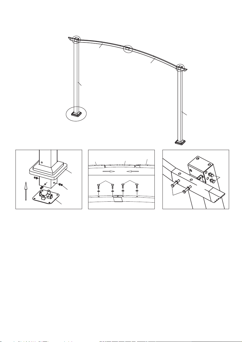
Fig.1: Insert Post(A1) to Base Plate Cover (J), then using Bolt (AA) to connect Post (A1 & A2)
and Base Plate (H). Repeat each step for A1/A2.
Fig.2: Insert Connector Tube (F) to Roof Tube Curved (B1 & B2), make sure the holes are aligned.
Using Bolt (AA) to connect Connector Tube (F) and Roof Tube Curved (B1 & B2).
Fig.3: Using Bolt (AA) and Bolt (BB) to connect Roof Tube Curved (B2) and Post (A2), Using
Bolt (AA) and Bolt (BB) to connect Roof Tube Curved (B1) and Post (A1).
Page 5
STEP 2
Fig. 5
B2
C2
Fig. 4
C1
Fig. 5
B1
B2
A1
Fig.4 Fig.5
C1
G
C2
Fig. 5
AA
B1
Fig. 5
C1
C2
A1
A2
C1/C2
AA
C2
B1/B2
C1
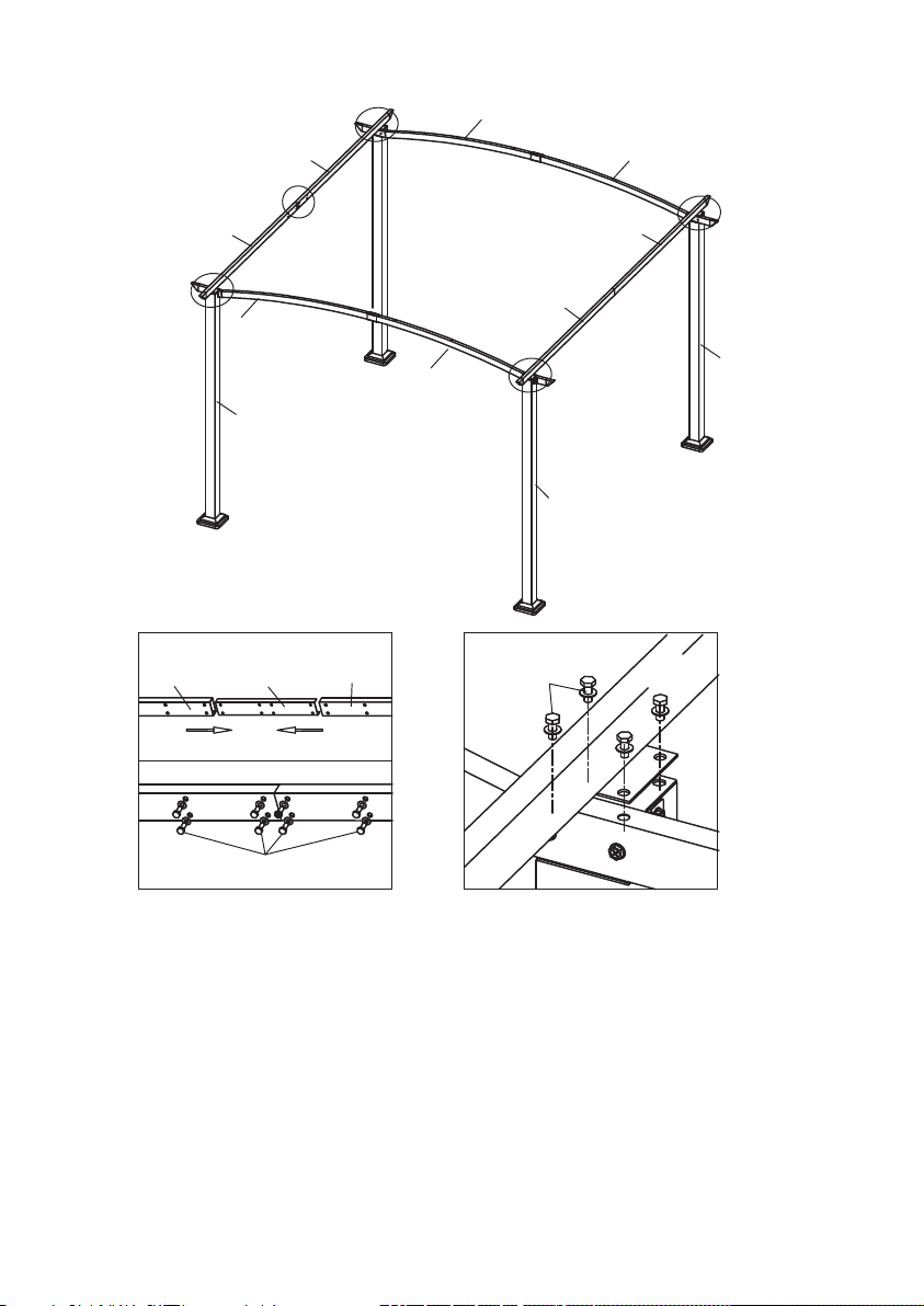
Fig.4: Insert Connector Tube (G) to Lintel (C1) and Lintel (C2), make sure the holes are aligned.
Then use Bolt (AA) to connect Lintel (C1), Lintel (C2) and Connector Tube (G).
Fig.5: Using Bolt (AA) to connect Lintel (C1) and Roof Tube Curved (B1). Using Bolt (AA)
to connect Lintel (C2) and Roof Tube Curved (B2).
Page 6

STEP 3
Fig. 7
B2
D2
Fig. 6
D1
B1
Fig. 7
Fig.6 Fig.7
D1
AA
D2
B2
B1
D2
Fig. 6
D1
CC
D1/D2
B1/B2
Fig.6: Using Bolt (AA) to connect Roof Tubes (D1 &D2).
Fig.7: Using Bolt (CC) to connect Roof Tube Curved (B1) and Roof Tubes (D1) / Roof Tube
Curved (B2) and Roof Tubes (D2) / Roof Tube Curved (B1) and Roof Tubes (D2) / Roof Tube
Curved (B2) and Roof Tubes (D1).
Page 7
STEP 4
K
E2
Fig. 9
Fig. 8 Fig. 9 Fig. 10
Fig. 8
E1
Fig. 10
K
E1
CLICK!
E2
E1 & E2
DD
H
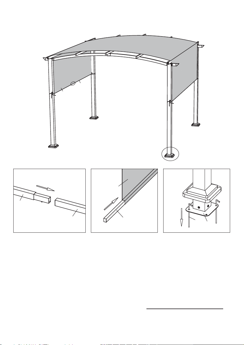
Fig.8: Insert Weight Bar (E1) to Weight Bar (E2) till you will see the push pin out from the tube.
Fig.9: Pass the Shade Fabric K through the Roof Tube (D1/D2) in turn as above diagram. Make
sure Cross Beam (C1/C2) on the edge support the Shade Fabric underneath. Insert the Pulling
Rod (E1/E2) to Shade Fabric. After assembled, please pull the Shade Fabric, make sure it runs
smoothly.
Fig.10: Move up the Base Plate Cover (J), insert Anchor (DD) to Base Plate (H). Tie the fabric
rope on the post (A1/A2).
Any questions on assembly or parts, please contact: customerservice@e2e-corp.com
Made in china
 Loading...