

Page 1
ATTENTION: THIS BOOKLET DOESN'T SUBSTITUTE THE OPERATION AND
MAINTENANCE MANUAL. IT’S NECESSARY TO READ CAREFULLY AND UNDERSTAND
THE OPERATION AND MAINTENANCE MANUAL BEFORE CARRYING OUT ANY
MANOEUVRE WITH THE MACHINE.
QUICK INSTRUCTIONS FOR HINOWA LIGHTLIFT 2614 PERFORMANCE
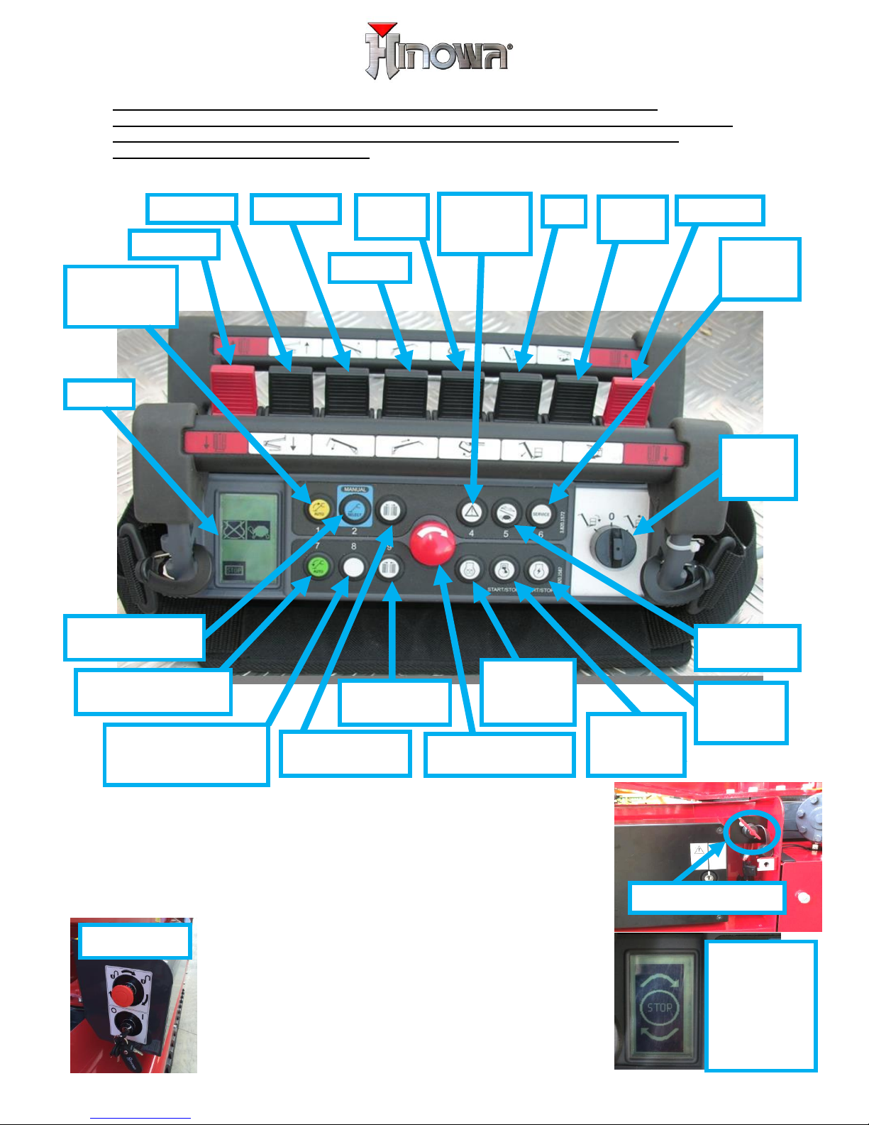
To start the machine battery cutter (under the bonnet) and
main key must be turned ON, if remote control display ask
to emergency STOP button must be pressed and released,
as reminded by the icon here on the right side. While all
the emergency stop buttons are released, thermic engine or
electric motor could be activated by pressing the relevant
buttons on the remote control (see picture
above).
Note1: On gasoline machine when the engine is
cold, once it’s ignited, it’s possible to warm it up
pressing the “WARM UP” button on the remote
control, engine will run faster for 20 seconds.
FIPE2614021701
Engine
preheat
button
Emergency STOP
button
Gravity
emergency
descent
Outriggers
automatic
retraction
Left track
1
st
cylinder
Jib
Turret
rotation
Right track
2
nd
cylinder
Basket
rotation
Extension
Basket
leveling
key
Electric
motor
(start-stop)
Thermic
engine
(start-stop)
Undercarriage
closing
Automatic
stabilization
Undercarriage
widening
Engine speed
selector
Stabilizers manual
operating
Service
menu
selector
Display
Permission of aerial
part operation from
ground
BATTERY CUTTER
MAIN KEY
PRESS AND
RELEASE
REMOTE
CONTROL
EMERGENCY
STOP
BUTTON
Page 2
TRACKS MOVEMENTS
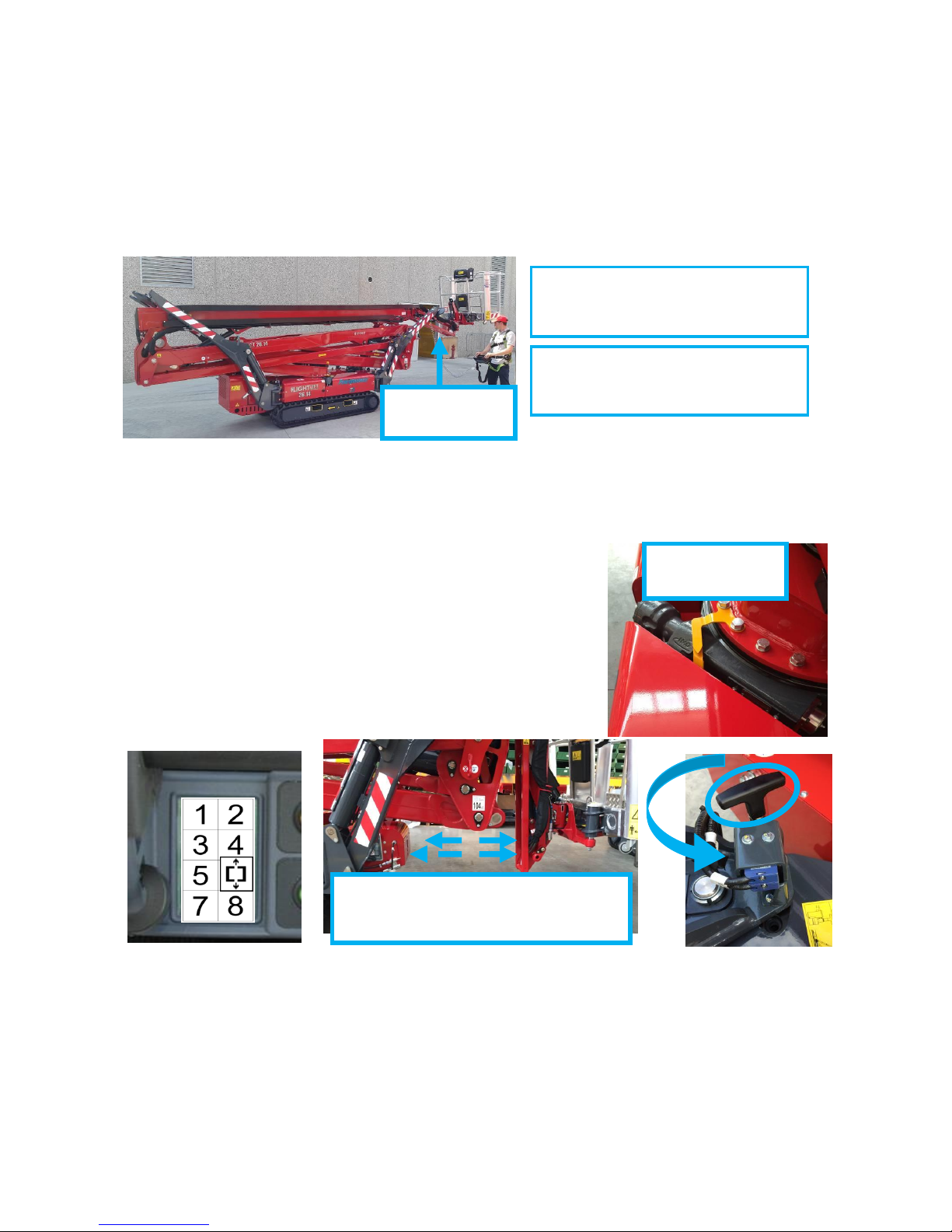
To move the tracks it’s necessary that all the outriggers are raised from the
ground. It’s possible to move the tracks even if jib arm (last arm, see picture
below) is opened but in this case basket should be empty, therefore the
operator must be at the ground keeping the remote control on his hands.
Otherwise when jib arm is closed the tracks could be moved operating from the
basket.
To move the tracks (with all the outriggers raised from the ground) press the
tracks red joystick on the remote control. To open the jib arm press the jib
movement joystick. Jib should be closed to allow outriggers movements. Tracks
speed could be limited by an automatic speed control that prevent unsafe
translation conditions.
OUTRIGGERS MOVEMENTS
To move the outriggers it’s necessary that the
machine is perfectly closed and aligned (all the arms
and the jib closed). In this case the display shows
the MACHINE CLOSED AND ALIGNED icon (see the
picture below on the left). To move the outriggers
the remote control could be in the basket support or
the operator can keep it in his hands also standing
on the ground.
OUTRIGGERS UNBLOCKING
Outrigger to be moved need to be opened. To open each outrigger it’s
necessary to lift the mechanic block shown by picture lifting the handle and at
the same time rotating the outrigger manually. To move aerial part machine
must be stabilized.
AUTOMATIC STABILIZATION:
To stabilize the machine automatically the machine must be closed aligned
(all the arms and the jib closed and turret aligned).
TRANSLATION WITH JIB CLOSED
IS POSSIBLE FROM THE GROUND
OR FROM THE BASKET.
TRANSLATION WITH JIB OPENED
IS POSSIBLE ONLY WHEN
OPERATOR AT THE GROUND
JIB ARM
OPENED
ALIGNMENT
ARROWS
PHOTOCELLS SYSTEM DETECTS
WHEN MACHINE IS CLOSE AND
ALIGNED
Page 3
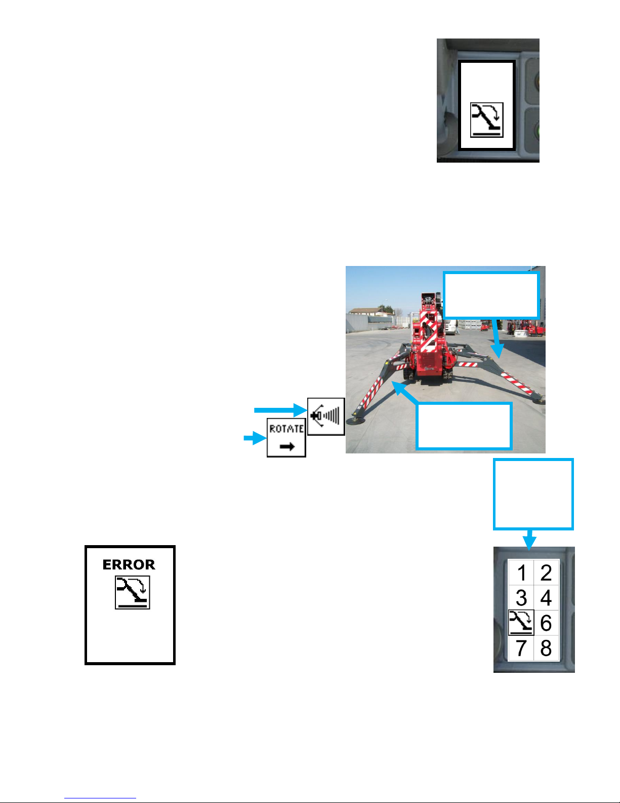
Pressing the green button (number 7) on the remote control
the machine start the automatic stabilization procedure.
That procedure will be completed only when the display will
shows the MACHINE STABILIZED icon (see the picture on
the right). Stabilisation is the necessary condition to allow
aerial part movements.
MANUAL STABILIZATION:
It’s also possible to move the outriggers one by one pressing the blue button
(number 2) and following the indications given on the display. Automatic
Stabilisation remain the recommended procedure.
AUTOMATIC OUTRIGGERS RETRACTION:
To bring back the platform in transportation configuration (all the outriggers
completely lifted), once that the aerial part is closed and aligned, keep pressed
the yellow button (number 1) on the remote control.
VARIABLE STABILIZATION AREA:
It’s possible to stabilize the machine in a
reduced area, indeed each outrigger could
be opened totally or partially. For stability
reason the turret rotation will be
automatically reduced on one side in case of
both outriggers of that side are not totally
opened. If even one outrigger is opened
only partially, display will show the
“REDUCED STABILIZATION AREA” icon.
Attempting to exit the
allowed working area display
will show the “ROTATE” icon.
AERIAL PART MOVEMENTS
To move the aerial part the remote control must be positioned in its
basket support. Aerial part movements are possible only when
machine is stabilized and therefore when the MACHINE STABILIZED
icon appears in position 5 of the display. If one stabilization condition
is missing, when a joystick is moved the display indicates the missing
condition with “FAIL” as follows.
ST”X” FAIL indicates that outrigger n.”X” is not
touching the ground.
INCL FAIL means that the machine is not levelled
within the inclination clearance.
LOAD FAIL means that basket is overloaded (more
than 230Kg into the basket so more than about 280
Kg read by the input menu).
BASKET FAIL means that the remote control is
not properly placed on its basket support (it does not
feel the remote control support magnet).
PEDAL (OPTIONAL) FAIL means that pedal option is activated
and pedal is not properly pressed in order to allow the
movement.
AUTOST FAIL means auto-stabilization procedure not complete
properly.
OK
OUTRIGGER
TOTALLY OPENED
OUTRIGGER
PARTIALLY
OPEND
MACHINE
STABILIZED
ICON ON
THE
DISPLAY
ST1 FAIL
INCL FAIL
BASKET FAIL
Page 4
After work is finished close carefully and completely all the arms and perfectly
align the turret looking at the yellow arrows. Than the outriggers could be
lifted and the tracks moved.
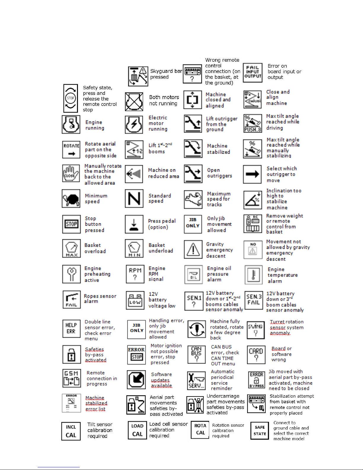
LIST OF DISPLAY ICONS
 Loading...