

Hino Motors HINO 155, HINO 195h, HINO 155h, HINO 195 Workshop Manual

MENU
FOREWORD
This workshop manual has been prepared to provide information regarding repair procedures on Hino Trucks.
Applicable for HINO 155, 155h, 195, 195h series, equipped with J05E engine
When making any repairs on your vehicle, be careful not to be injured through improper procedures.
As for maintenance items, refer to the Owner
All information and specifications in this manual are based upon the latest product information available at the time of printing.
Hino Motors Sales U.S.A., Inc. reserves the right to make changes at any time without prior notice.
Please note that the publications below have also been prepared as relevant workshop manuals for the components and systems in these vehicles.
Chassis Workshop Manual
J05E Engine Workshop Manual S5-LJ05E07A
Trouble shooting Workshop Manual
's Manual.
Manual Name Pub. No.
S1-LXJE05A
S1-LXJE05A EWD
S7-LXJE05A 2/5
S7-LXJE05A 3/5
S7-LXJE05A 4/5
S7-LXJE05A 5/5

CHAPTER REFERENCES REGARDING THIS WORKSHOP MANUAL
Use this chart to the appropriate chapter numbers for servicing your particular vehicle.
MANUAL No. S7-LXJE05A 1/5 (U.S.A.), S7-LXJE06A 1/5 (CANADA)
CHAPTER
GENERAL INTRODUCTION 1-001
ENGINE 2-001 (J05E)
MODELS HINO 155, 155h, 195, 195h
Production Code XFC710, XFC720, XFC730, XFC740,
XJC700, XJC710, XJC720,XJC730, XJC740

INDEX: TROUBLE SHOOTING GROUP 1/2
GENERAL INTRODUCTION
ENGINE
HYBRID
WORKSHOP
MANUAL
TRANSMISSION
CLUTCH
PROPELLER SHAFT
AXLE
DIFFERENTIAL
BRAKE
STEERING
SUSPENSION
All rights reserved. This manual may not be
reproduced or copied in whole in part, without the written consent of Hino Motors, Ltd.
FRAME AND FRAME ACCESSORY
CAB MOUNTING AND CAB SUSPENSION
BODY CONSTRUCTION
BODY INSIDE ACCESSORY
BODY OUTSIDE ACCESSORY
AIR BAG AND SEAT BELT
HEATER AND AIR CONDITIONER

INDEX: TROUBLE SHOOTING GROUP 2/2
ELECTRICAL
CONTROL SYSTEM

GENERAL INTRODUCTION 1–1
1
GENERAL INTRODUCTION
HOW TO IDENTIFY VEHICLE TYPE .............. 1-2
HOW TO IDENTIFY VEHICLE TYPE ...........................1-2
VEHICLE TYPE ......................................................1-2
VEHICLE IDENTIFICATION NUMBER (VIN)
STRUCTURE ..........................................................1-3
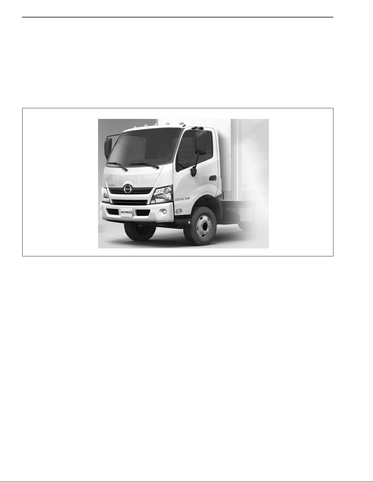
APPEARANCE OF VEHICLE ......................... 1-4
APPEARANCE.............................................................1-4
APPEARANCE OF VEHICLE .................................1-4
1-001
SAFETY INSTRUCTIONS AND
READINESS TO WORK .................................. 1-5
WARNING ....................................................................1-5
GENERAL PRECAUTIONS ....................................1-5
IDENTIFICATION INFORMATION ........................1-10
SAFETY INSTRUCTIONS FOR WORK.....................1-13
PRECAUTIONS ....................................................1-13
INTRODUCTION TO WORKSHOP MANUAL............1-17
GENERAL .............................................................1-17
INTRODUCTION TO DESCRIPTIONS................. 1-18
DEFINITION OF TERM.........................................1-21
TROUBLE SHOOTING.................................. 1-22
TROUBLESHOOTING WITH
DIAGNOSIS MONITOR ..............................................1-22
TROUBLESHOOTING PROCEDURE ..................1-22
APPARATUS FOR TROUBLE SHOOTING...........1-24
TROUBLE DIAGNOSIS USING THE COMPUTER
(HINO DX Ⅱ ) .............................................................1-25
STEP OF TROUBLE DIAGNOSIS ........................1-25
APPARATUS FOR TROUBLE DIAGNOSIS.......... 1-26
GLOSSARY ................................................... 1-27
DEFINITION OF ABBREVIATION .............................1-27
LIST OF ABBREVIATION .....................................1-27
GLOSSARY OF SAE AND HINO TERMS ............ 1-30
GENERAL INTRODUCTION/HOW TO IDENTIFY VEHICLE TYPE1–2
X
Ԙ
J
ԙ
C
Ԛ
7
ԛ
0
Ԝ
0
ԝԞ
L
ԟ
H
Ԡ
K
ԡ
T
Ԣ
Q
ԣ
L
Ԥ
A
ԥ
3
Ԧ
CLASSIFICATION
REPORTED MODEL
Ԙ
J05E-UG (HV)
X
X
ԙ
F
J05E-TP (Diesel)
J
㧦ENGINE MODEL
Ԛ
C
㧦VEHICLE MODEL
HEAVY DUTY TRACK
ԛ
㧦CAB WIDTH, DRIVE, FRAME FORM, WHEEL BASE
Ԝ
70
71
72
73
CAB WIDTH
DRIVE WHEEL BASE
FRAME ASSEMBLY WIDTH
FRAME
FORM
WIDE 2WD MEDIUMOPEN
WIDE 2WD LONGOPEN
WIDE 2WD SUPER LONGOPEN
WIDE 2WD SUPER LONGOPEN
840 mm {33 in.}
2,900 mm {114 in.}
3,500 mm {138 in.}
3,800 mm {150 in.}
4,100 mm {161 in.}
ԝ0㧦TYPE OF SUSPENSION
FRONT RIGID, REAR RIGID
Ԡ
CAB FORM BRAKE TYPE
㧦CAB FORM, BRAKE TYPE
ԟ
㧦STEERING WHEEL POSITION
L
LEFT HAND DRIVE
H
Q
SINGLE CAB VACUUM
CREW CAB VACUUM
C
D
SINGLE CAB HYDRAULIC
CREW CAB HYDRAULIC
ԡ
㧦DECK HEIGHT
K
HIGH FLOOR CAB
Ԣ
㧦TRANSMISSION
T
6AT
Ԧ
㧦DECK FORM
3
CHASSIS WITH CAB
Ԥ
㧦ENGINE HORSEPOWER, FUEL
FUEL
HORSEPOWER EXHAUST
VERY HIGH US13 (13OBD)
DIESEL OIL
M
ԣ
㧦LOADING CAPACITY, GVW, REAR TIRES
ԥ
㧦DESTINATION
DESTINATION
A
U.S., CANADA
6.58 t {14,500 lbs}
8.14 t {17,950 lbs},
8.85 t {19,500 lbs}
Q
T
74
WIDE 2WD SUPER LONGOPEN 4,400 mm {173 in.}
REAR DOUBLE
REAR DOUBLE
SHTS01ZZZ0100001
HOW TO IDENTIFY VEHICLE TYPE
HOW TO IDENTIFY VEHICLE TYPE
VEHICLE TYPE
EN01H01ZZZ010102001001

GENERAL INTRODUCTION/HOW TO IDENTIFY VEHICLE TYPE 1–3
WMI VDS CD VIS
(1) (2) (3) (4) (5) (6) (7) (8) (9)
(10) (11) (12) (13) (14) (15) (16)
JHH KDL 2H X C K00100
(17)
1
MANUFACTURER ,TYPE
MODEL, CAB TYPE,
WHEEL BASE,
BRAKE SYSTEM
MODEL YEAR
ENGINE MODEL
ASSEMBLY PLANTSERIES
MAKE
CHECK DIGIT
SEQUENTIAL NUMBER
CODE
JHN INCOMPLETE VEHICLE
TYPEMANUFACTURER
HINO MOTORS, LTD.
2AY
INCOMPLETE VEHICLE
HINO MOTORS
CANADA, LTD.
CODE CODE YEARYEAR
K 2019
L 2020
M 2021
E 2014
F 2015
G 2016
CODE
PM Hybrid
APPLICATIONENGINE MODEL
J05E-UG
DM DieselJ05E-TP
CODE
For USA
For Canada
1
2
ASSEMBLY PLANT
CODE
CODE
H
MAKE
SERIES GVWR
HINO
6,580 kg
{14,500 lbs.}
8,140 - 8,850 kg
{17,950 - 19,500 lbs.}
CODE CLASS MODEL
PRODUCTION
CODE
CAB TYPE WHEEL BASE
BRAKE
SYSTEM
CODE
1
ASSEMBLY PLANT
HINO MOTORS, LTD.
Hamura Plant in Japan
K
HINO MOTORS, LTD.
Hamura Plant in Japan
K
Canada Plant (COE)
N 2022
P 2023
H 2017
J 2018
R
S
T
U
V
W
X
Y
P
H
K
L
HINO 195h
HINO 195
HINO 195
HINO 195
HINO 155
HINO 155
HINO 155
HINO 155
HINO 195
HINO 195
HINO 155
HINO 155
5
5
5
5
4
4
5
5
4
4
4
4
XFC710
HINO 155h
XFC720
HINO 155h
XFC740
HINO 195h
XFC720
HINO 195h
XFC740
HINO 155h
XFC710
HINO 195h
XFC720
HINO 195h
XFC740
HINO 155h
XFC740
HINO 155h
XFC720
HINO 195 XJC710
COE
SINGLE CAB
COE
SINGLE CAB
COE
SINGLE CAB
COE
SINGLE CAB
COE
SINGLE CAB
COE
SINGLE CAB
COE
SINGLE CAB
COE
SINGLE CAB
COE
CREW CAB
COE
CREW CAB
COE
CREW CAB
COE
CREW CAB
3500mm{138 in.}
3500mm{138 in.}
2900mm{114 in.}
2900mm{114 in.}
3800mm{150 in.}
3800mm{150 in.}
3800mm{150 in.}
3800mm{150 in.}
4400mm{173 in.}
4400mm{173 in.}
4400mm{173 in.}
4400mm{173 in.}
XJC700
XJC700
XJC710
XJC720
XJC740
XJC740
XJC720
XJC720
XJC740
XJC720
XJC740
HYDRAULIC
G
HINO 195h
5
XFC730
HINO 195 XJC730
COE
SINGLE CAB
4100mm{161 in.} HYDRAULIC
HYDRAULIC
HYDRAULIC
HYDRAULIC
HYDRAULIC
HYDRAULIC
VACUUM
VACUUM
VACUUM
VACUUM
VACUUM
VACUUM
SHTS01ZZZ0100002
VEHICLE IDENTIFICATION NUMBER (VIN) STRUCTURE
EN01H01ZZZ010102001002
GENERAL INTRODUCTION/APPEARANCE OF VEHICLE1–4
SHTS01ZZZ0200001
APPEARANCE OF VEHICLE
APPEARANCE
APPEARANCE OF VEHICLE
EN01H01ZZZ020101003001

GENERAL INTRODUCTION/SAFETY INSTRUCTIONS AND READINESS TO WORK 1–5
SAFETY INSTRUCTIONS AND READINESS TO WORK
WARNING
GENERAL PRECAUTIONS
EN01H01ZZZ030101001001
Some recommended and standard maintenance services for your vehicle are included in this section. When performing
maintenance on your vehicle be careful not to get injured by improper work. Improper or incomplete work can cause a malfunction of the vehicle which may result in personal injury and/or property damage. If you have any question about performing maintenance, please consult your Hino dealer.
WARNING
When working on your vehicle, observe the following general precautions to prevent death, personal injury and/
or property damage in addition to the particular DANGERS, WARNINGS, CAUTIONS and NOTICES in each chapter.
• Always wear safety glasses or goggles to protect your eyes.
• Remove rings, watches, ties, loose hanging jewelry and loose clothing before starting work on the vehicle.
• Bind long hair securely behind the head.
• When working on the vehicle, apply the parking brake firmly, place the gear shift lever in "Neutral" or "N" and
block the wheels.
• Always turn off the starter switch to stop the engine, unless the operation requires the engine running.
Removing the key from the switch is recommended.
• To avoid serious burns, keep yourself away from hot metal parts such as the engine, exhaust manifold, radia-
tor, muffler, exhaust pipe and tail pipe.
• Do not smoke while working on the vehicle since fuel, and gas from battery are flammable.
• Take utmost care when working on the battery. It contains corrosive sulfuric acid.
• Large electric current flows through the battery cable and starter cable. Be careful not to cause a short which
can result in personal injury and/or property damage.
• Read carefully and observe the instructions specified on the jack before using it.
• Use safety stands to support the vehicle whenever you need to work under it. It is dangerous to work under a
vehicle supported only by a jack.
• If it is necessary to run the engine after the hood is raised (tilted), make sure that the parking brake is firmly
applied, the wheels are blocked, and the gear shift lever is positioned in "Neutral" before staring the engine.
• Run the engine only in a well-ventilated area to avoid inhalation of carbon monoxide.
• Keep yourself, your clothing and your tools away from moving parts such as the cooling fan and V-belts when
the engine is running.
• Be careful not to damage lines and hoses by stepping or holding your feet on them.
• Be careful not to leave any tool in the engine compartment. The tool may be hit by moving parts, which can
cause personal injury.
GENERAL INTRODUCTION/SAFETY INSTRUCTIONS AND READINESS TO WORK1–6
! WARNING
B
F
E
G
SHTS01ZZZ0300001
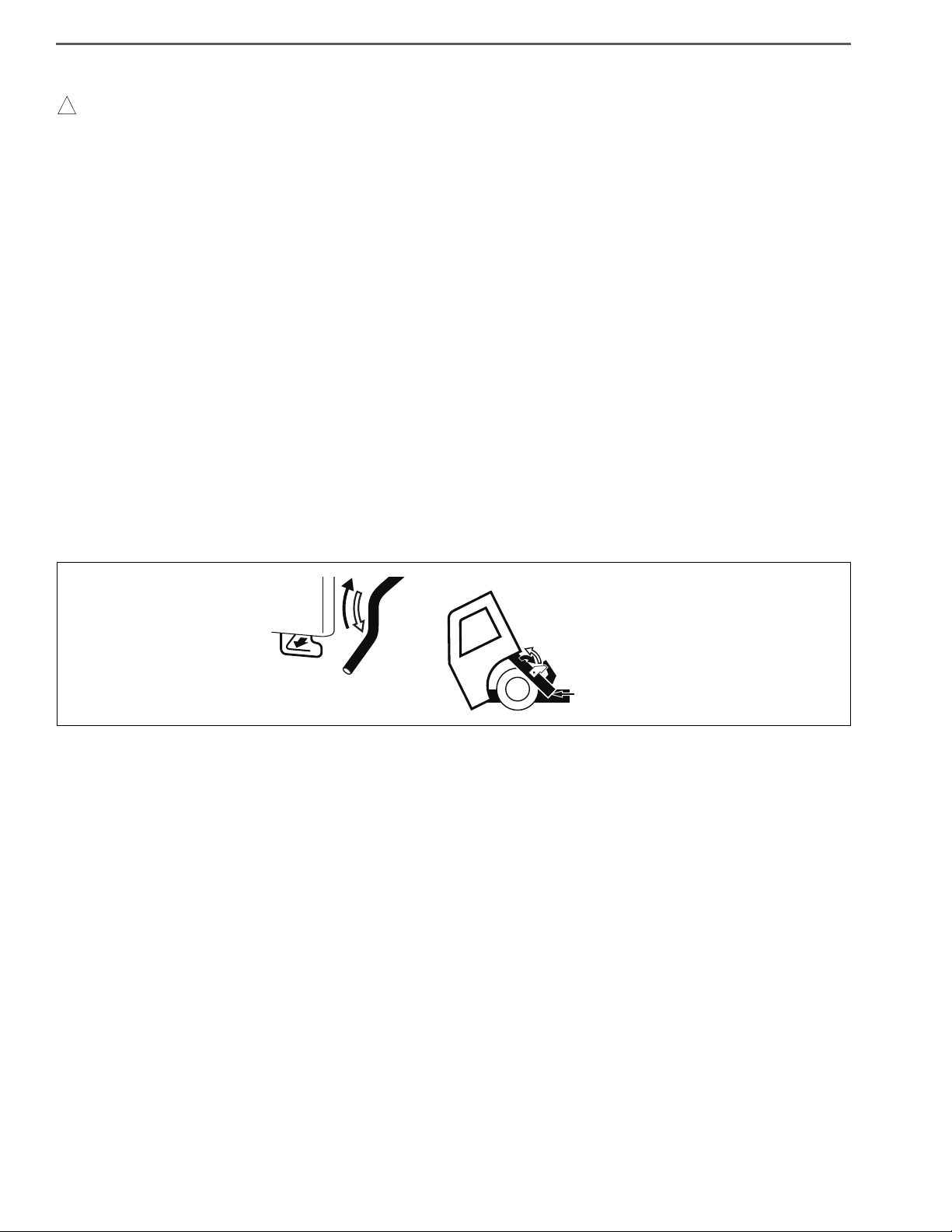
PRECAUTIONS IN TILTING AND LOWERING THE CAB
Be sure to observe the following when tilting and lowering the cab to reduce the risk of an accident which may
result in death, serious injury and/or property damage.
• Park the vehicle on a level place and ensure ample space around the cab before tilting the cab.
• Apply the parking brake firmly and place the gearshift lever in “N” position (“P” position if your vehicle is
equipped with automatic transmission).
• Stop the engine and block the wheels.
• Remove any articles in or over the cab and close the doors firmly.
• Make sure there is no one in or around the cab and there are no obstacles in front of the vehicle or above the
cab.
• The catch (E), stopper (F), stay (G) and other parts such as the engine, radiator, and exhaust pipe can be very
hot while your vehicle is operated. Be sure to confirm they have been cooled down before you start working
under the cab.
• Never raise or lower the cab only by yourself if your cab is equipped with heavy component such as a roof rack.
• Never put your body under the cab while raising or lowering the cab.
• Make sure the cab stopper stay is securely locked by the catch (E) and raise the stopper (F) to lock the catch (E)
completely after raising the cab.
• Before lowering the cab, make sure that any object such as hand tools, gloves or cloth are not left under the
cab.
• Make sure the handle (B) is caught by the catch after lowering the cab.
Read the Owner’s manual for details.
GENERAL INTRODUCTION/SAFETY INSTRUCTIONS AND READINESS TO WORK 1–7
DEFINITION OF SAFETY TERMS
Indicates an extremely hazardous situation if proper procedures are not followed and
could result in death or serious injury.
Indicates a potential hazardous situation if proper procedures are not followed and
could result in death or serious injury.
Indicates a hazardous situation if proper procedures are not followed and could result
in serious injury or damage to parts/equipment.
Indicates the need to follow proper procedures and to pay attention to precautions so
that efficient service is provided.
Provides additional information to help you to perform the repair efficiently.

GENERAL INTRODUCTION/SAFETY INSTRUCTIONS AND READINESS TO WORK1–8
TOWING
• When being towed, always place the gear shift lever in "Neutral" and release the parking brake completely. In order to
protect the bumper, fit a protection bar against the lower edge of the bumper and put a wood block under the frame near
the No. 1 cross member when attaching the towing chain. Never lift or tow the vehicle if the chain is in direct contact with
the bumper.
1. Towing procedures
(1) Make sure that the propeller shaft of the vehicle to be towed is removed. When the differential gear or rear axle
shaft is defective, remove both right and left rear axle shafts, then cover the hub opening to prevent loss of axle
lubricant and entry of dirt or foreign matter.
(2) Use a heavy duty cable or rope when towing the vehicle. Fasten the cable securely to the towing hook on the
frame.
(3) The angle of pulling direction of the cable fastened to the towing hook must not exceed 15° in horizontal and ver-
tical directions from the straight ahead, level direction. Avoid using the hook in a way that subjects it to jerk, as in
towing a vehicle trapped in a gutter.
(4) Keep the gear shift lever in Neutral.
(5) Make sure that the starter switch is kept in the "ON" position, if the engine is not running.
(6) Make sure that the engine of the towed vehicle is kept running. If the engine is off, no compressed air/ no vac-
uum will be available for the brake. This is dangerous, as the brake system does not function if the engine is not
running.
In addition, the power steering system will not function. The steering wheel, therefore, will become unusually
hard to turn, making it impossible to control the vehicle.
(7) Note that the engine brake and exhaust brake cannot be applied, if the propeller shaft is removed.
(8) Make a slow start to minimize shock. Towing speed should be less than 30 km/h {18 mile/h}.
2. If the engine of the towed vehicle is defective, make sure that the vehicle is towed only by a tow truck
designed for that purpose.
(1) Front end towing (with front wheels raised off the ground)
When towing from the front end with the front wheels raised off the ground, remove the rear axle shafts to protect
the transmission and differential gears from being damaged. The hub openings should be covered to prevent the
loss of axle lubricant or the entry of dirt or foreign matter. The above-mentioned precautions should be observed
for vehicles equipped with either manual or automatic transmission, and for even short distance towing. After
being towed, check and refill the rear axle housing with lubricant if necessary.
(2) Rear end towing
When being towed with the rear wheels raised off the ground, fasten and secure the steering wheel in a straightahead position.

GENERAL INTRODUCTION/SAFETY INSTRUCTIONS AND READINESS TO WORK 1–9
CLEAN AIR ACT
1. Heavy-duty engine rebuilding practices.
§ 86.004-40
• The provisions of this section are applicable to heavy-duty engines subject to model year 2004 or later standards
and are applicable to the process of engine rebuilding (or rebuilding a portion of an engine or engine system). The
process of engine rebuilding generally includes disassembly, replacement of multiple parts due to wear, and reassembly, and also may include the removal of the engine from the vehicle and other acts associated with rebuilding
an engine. Any deviation from the provisions contained in this section is a prohibited act under section 203(a) (3) of
the Clean Air Act (42 U.S.C. 7522(a) (3)).
(1) When rebuilding an engine, portions of an engine, or an engine system, there must be a reasonable technical
basis for knowing that the resultant engine is equivalent, from an emissions standpoint, to a certified configuration (i.e., tolerances, calibrations, specifications) and the model year(s) of the resulting engine configuration must
be identified. A reasonable basis would exist if:
a. Parts installed, whether the parts are new, used, or rebuilt, are such that a person familiar with the design and
function of motor vehicle engines would reasonably believe that the parts perform the same function with
respect to emissions control as the original parts; and
b. Any parameter adjustment or design element change is made only:
• In accordance with the original engine manufacturer's instructions; or
• Where data or other reasonable technical basis exists that such parameter adjustment or design element
change, when performed on the engine or similar engines, is not expected to adversely affect in-use emissions.
(2) When an engine is being rebuilt and remains installed or is reinstalled in the same vehicle, it must be rebuilt to a
configuration of the same or later model year as the original engine. When an engine is being replaced, the
replacement engine must be an engine of (or rebuilt to) a configuration of the same or later model year as the
original engine.
(3) At time of rebuild, emissions-related codes or signals from on-board monitoring systems may not be erased or
reset without diagnosing and responding appropriately to the diagnostic codes, regardless of whether the systems are installed to satisfy requirements in § 86.004-25 or for other reasons and regardless of form or interface.
Diagnostic systems must be free of all such codes when the rebuilt engine is returned to service. Such signals
may not be rendered inoperative during the rebuilding process.
(4) When conducting a rebuild without removing the engine from the vehicle, or during the installation of a rebuilt
engine, all critical emissions-related components listed in § 86.004-25(2) not otherwise addressed by paragraphs (1) through (3) of this section must be checked and cleaned, adjusted, repaired, or replaced as necessary, following manufacturer recommended practices.
(5) Records shall be kept by parties conducting activities included in paragraphs (1) through (4) of this section. The
records shall include at minimum the mileage and/or hours at time of rebuild, a listing of work performed on the
engine and emissions-related control components including a listing of parts and components used, engine
parameter adjustments, emissions-related codes or signals responded to and reset, and work performed under
paragraph (4) of this section.
a. Parties may keep records in whatever format or system they choose as long as the records are understand-
able to an EPA enforcement officer or can be otherwise provided to an EPA enforcement officer in an understandable format when requested.
b. Parties are not required to keep records of information that is not reasonably available through normal busi-
ness practices including information on activities not conducted by themselves or information that they cannot
reasonably access.
c. Parties may keep records of their rebuilding practices for an engine family rather than on each individual
engine rebuilt in cases where those rebuild practices are followed routinely.
d. Records must be kept for a minimum of two years after the engine is rebuilt.
2. Maintenance instructions.
§ 86.010-38
(1) For each new diesel-fueled engine subject to the standards prescribed in § 86.007-11, as applicable, the manu-
facturer shall furnish or cause to be furnished to the ultimate purchaser a statement that
"This engine must be operated only with ultra low-sulfur diesel fuel (meeting EPA specifications for
highway diesel fuel, including a 15 ppm sulfur cap)."
GENERAL INTRODUCTION/SAFETY INSTRUCTIONS AND READINESS TO WORK1–10
A
B
SHTS01ZZZ0300007
IDENTIFICATION INFORMATION
EN01H01ZZZ030101001002
1. VEHICLE IDENTIFICATION NUMBER
(1) The vehicle identification number (VIN) is stamped on the
right frame, as shown in the illustration. This number has also
been stamped on the manufacture's plate.
A: Vehicle Identification Number (VIN)
B: Manufacturer's Plate
(2) VIN
See VEHICLE IDENTIFICATION NUMBER (VIN) STRUCTURE on the following page.
(3) PRODUCTION CODE AND VEHICLE COMPONENTS
MODEL (CLASS) HINO 155h (4) HINO 155 (4) HINO 195h (5) HINO 195 (5)
XJC700
XJC710
XJC720
XJC740
PRODUCTION CODE
XFC710
XFC720
XFC740
TRANSMISSION SERIES A465
1st 3.742
2nd 2.003
3rd 1.343
TRANSMISSION RATIO
4th 1.000
5th 0.773
6th 0.634
REAR AXLE SERIES SH13
SERVICE BRAKE Vacuum Hydraulic
PARKING BRAKE ACTING ON DIFFERENTIAL OUTPUT SHAFT
SUSPENSION LEAF
XFC710
XFC720
XFC730
XFC740
XJC700
XJC710
XJC720
XJC730
XJC740
GENERAL INTRODUCTION/SAFETY INSTRUCTIONS AND READINESS TO WORK 1–11
FOR ALL MODELS
SHTS01ZZZ0300008
A
SHTS01ZZZ0300009
A
SHTS01ZZZ0300010
SHTS01ZZZ0300011
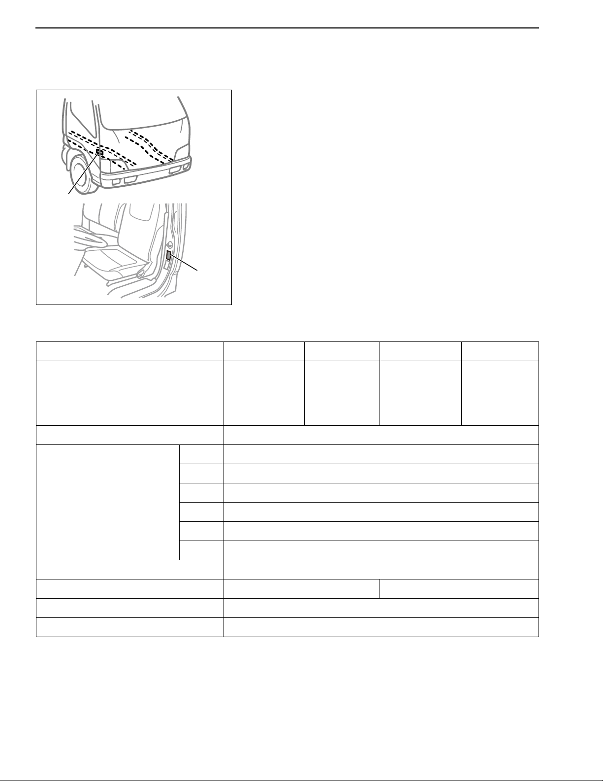
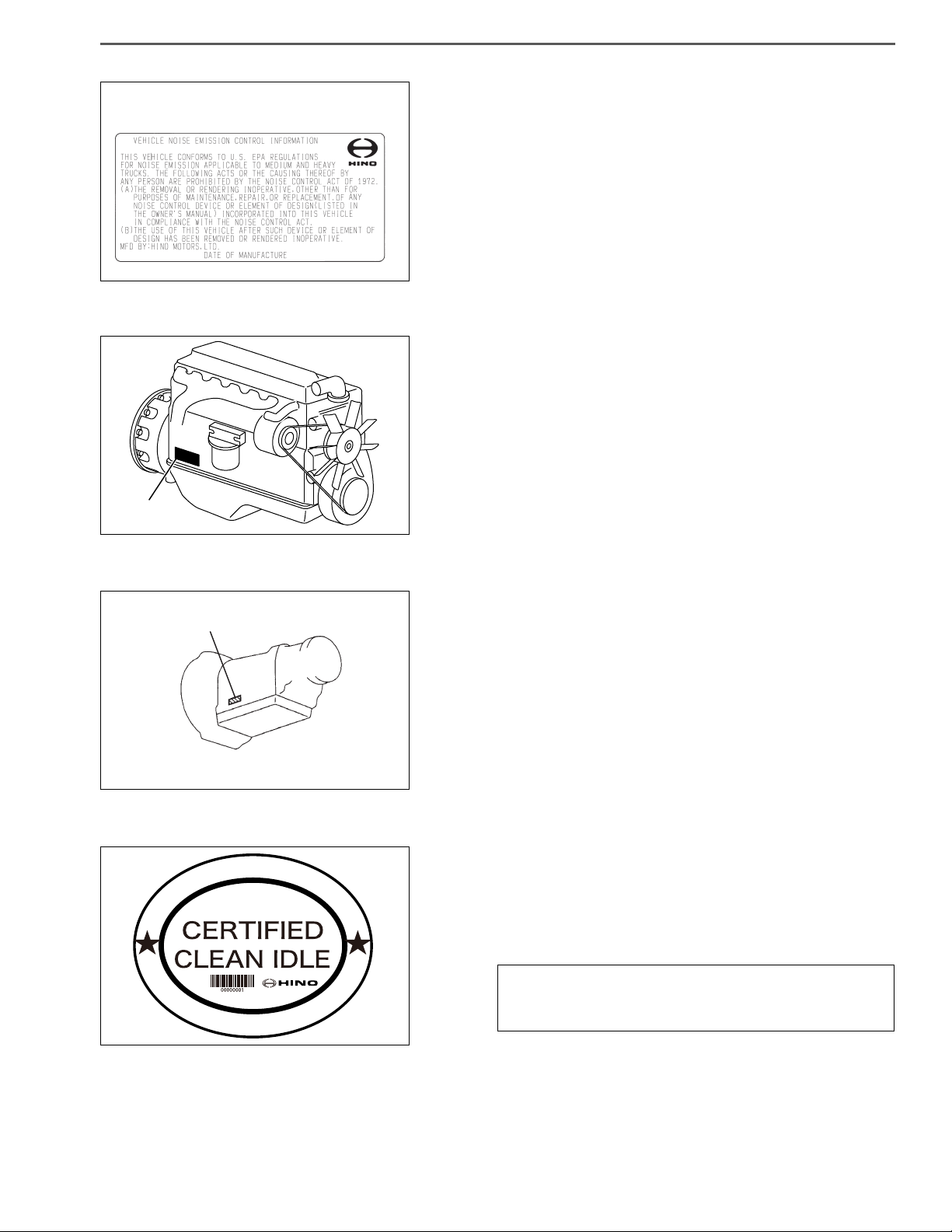
2. VEHICLE NOISE EMISSION CONTROL INFORMATION
• The Vehicle Noise Emission Control Information is affixed to the
left pillar of the cab. The name of manufacturer, production year
and month, and noise emission applicable to medium and heavy
trucks in conformity with U.S. EPA Regulations are displayed.
3. ENGINE SERIAL NUMBER
(1) The engine serial number is stamped on the cylinder block,
as shown in the illustration.
A: J05E
4. TRANSMISSION SERIAL NUMBER
(1) The transmission serial number is stamped on the transmis-
sion, as shown in the illustration.
A: A465
5. CLEAN IDLE CERTIFIED LABEL FOR U.S.
• Make sure that the following clean engine idling certified label is
affixed to the outside of the left door. By the CARB below, the
label must be affixed there to prove that the new vehicle with
diesel engine manufactured from Jan., 2008 conforms to this
low.
CARB § 1956.8. Exhaust Emission Standard and Test
Procedure (a) (b) Heavy-Duty Diesel Engine Idling
Requirements
GENERAL INTRODUCTION/SAFETY INSTRUCTIONS AND READINESS TO WORK1–12
Vehicle emission
control information
SHTS01ZZZ0300012
SHTS01ZZZ0300013
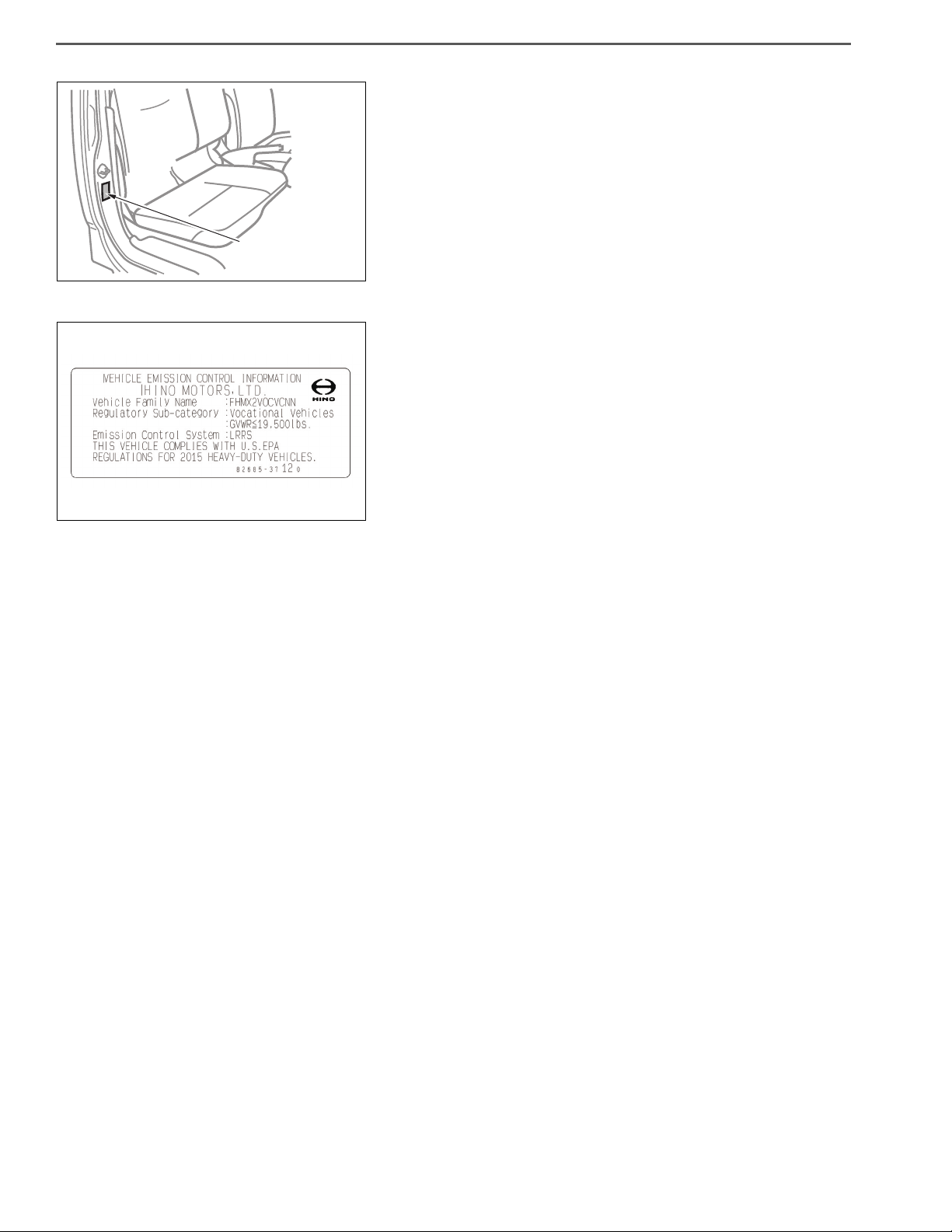
6. VEHICLE EMISSION CONTROL INFORMATION
• The Vehicle Emission Control Information is affixed to the side
of the right door. The name of manufacturer, production year
and month, and emission applicable to medium and heavy
trucks in conformity with U.S. EPA Regulations are displayed.
GENERAL INTRODUCTION/SAFETY INSTRUCTIONS AND READINESS TO WORK 1–13
! WARNING
SHTS01ZZZ0300014
SAFETY INSTRUCTIONS FOR WORK
PRECAUTIONS
EN01H01ZZZ030101004001
1. SAFETY INSTRUCTIONS FOR HANDLING ELECTRICAL SYSTEMS
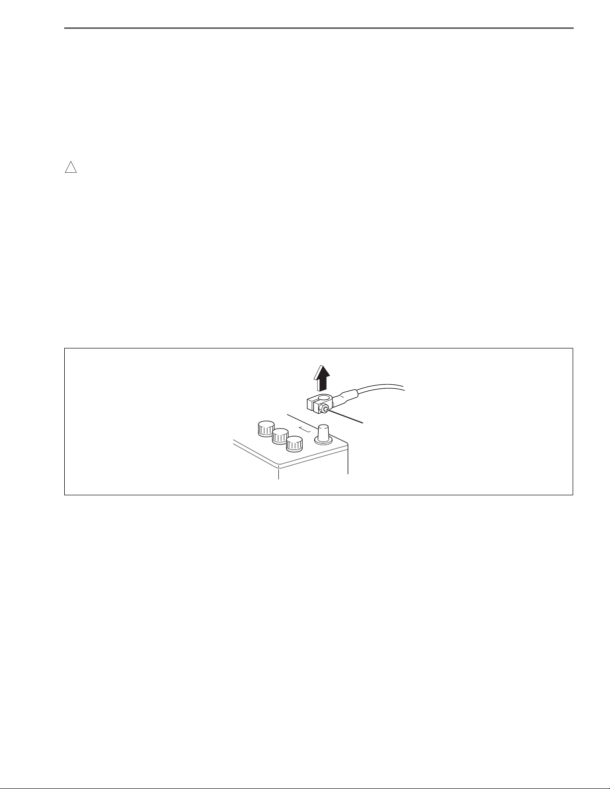
(1) Removing the battery cable
• Be sure to wait for at least ten minutes after the starter key is turned to "LOCK" position before you disconnect
the battery terminals from the battery, as the vehicle data is recorded on ECU and DCU starts working for the
exhaust gas after treatment after the starter key is turned to "LOCK" position. Otherwise, the vehicle data will
not be recorded on ECU properly and DCU will not complete working properly, which may result in the malfunction of DPR system and DEF-SCR system.
• The MIL (malfunction indicator light) may come on when the starter key is turned to "ON" position again, even if
you wait for at least ten minutes before disconnecting the battery terminals from the battery after the starter key
is turned to "LOCK" position. In this case, use HINO DXⅡ to clear the DTC (P204F and P068A), to turn off the MIL
and to conduct DPR regeneration manually.
a. Before electrical system work, remove the cable from the minus terminal of the battery in order to avoid burn-
ing caused by short-circuiting.
b. To remove the battery cable, fully release the nut to avoid damage to the battery terminal. Never twist the ter-
minal.
Loosen

GENERAL INTRODUCTION/SAFETY INSTRUCTIONS AND READINESS TO WORK1–14
SHTS01ZZZ0300015
SHTS01ZZZ0300016
(2) Handling of electronic parts
a. Never give an impact to electronic parts of a computer or relay.
b. Keep electronic parts away from high temperatures and humidity.
c. Never splash water onto electronic parts in washing the vehicle.
d. Do not remove the harness connector, electric component box, and cover except for repair and inspection.
If removal is necessary, pay attention that water and foreign matters do not attach or enter to the connector,
terminals, electric component box, and cover.
In restoration, make sure there is no attachment or entry of water and foreign matters and mount them properly, because it causes degradation of waterproof function.
Incorrect
(3) Handling of wire harness
a. Perform marking on a clamp and a clip and secure then in original position so that the wire harness will not
interfere with the end and acute angle section of the body and a bolt.
b. To attach a part, take care not to bite the wire harness.
Incorrect
Incorrect
Incorrect
GENERAL INTRODUCTION/SAFETY INSTRUCTIONS AND READINESS TO WORK 1–15
! WARNING
! WARNING
Incorrect
Incorrect
Correct
SHTS01ZZZ0300017
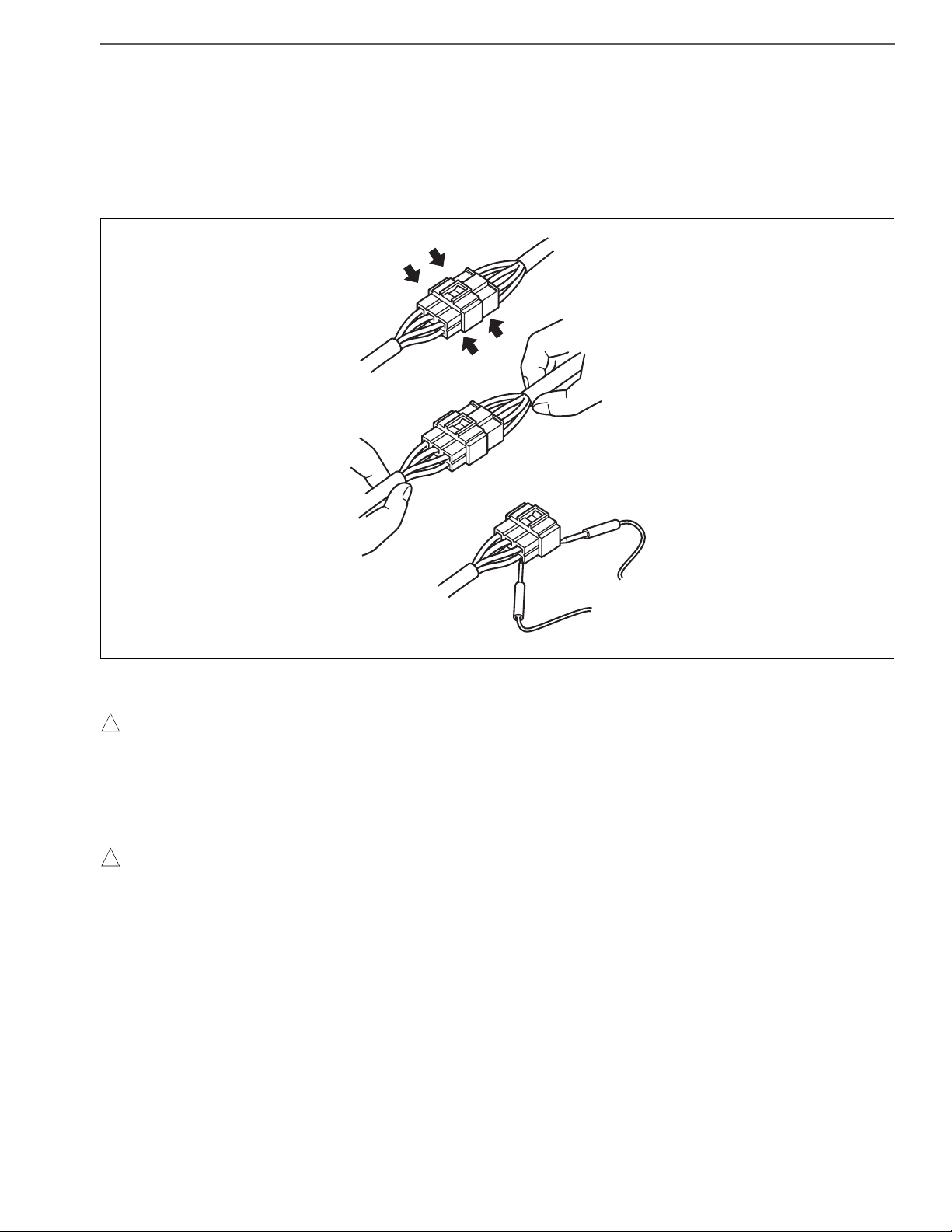
(4) Handling of connectors
a. When removing a connector, hold a connector (area shown in an arrow in the figure) and then pull it off. Do not
pull wire harnesses.
b. Pull off a lockable connector after unlocking.
c. When connecting a lockable connector, make sure to insert a lockable connector until it makes a click sound.
d. When inserting a test lead, insert it from the back of a connector.
e. If it is difficult to insert a test lead from the back of a connector, make and use an inspection harness.
(5) Installation of battery disconnect switch
• Installation of the battery disconnect switch on the power supply circuit for the dosing control unit of DEF-SCR
(DCU) may damage or result in the malfunction of DEF-SCR system.
• Be sure to read and follow the procedures and instructions on the service bulletin before the installation of the
battery disconnect switch.
(6) Handling of battery disconnect switch
• Wait for at least ten minute before using the battery disconnect switch after the starter key is turned to "LOCK"
position.
Otherwise, the vehicle data will not be recorded on ECU properly, which may result in the malfunction of DPR
system.
GENERAL INTRODUCTION/SAFETY INSTRUCTIONS AND READINESS TO WORK1–16
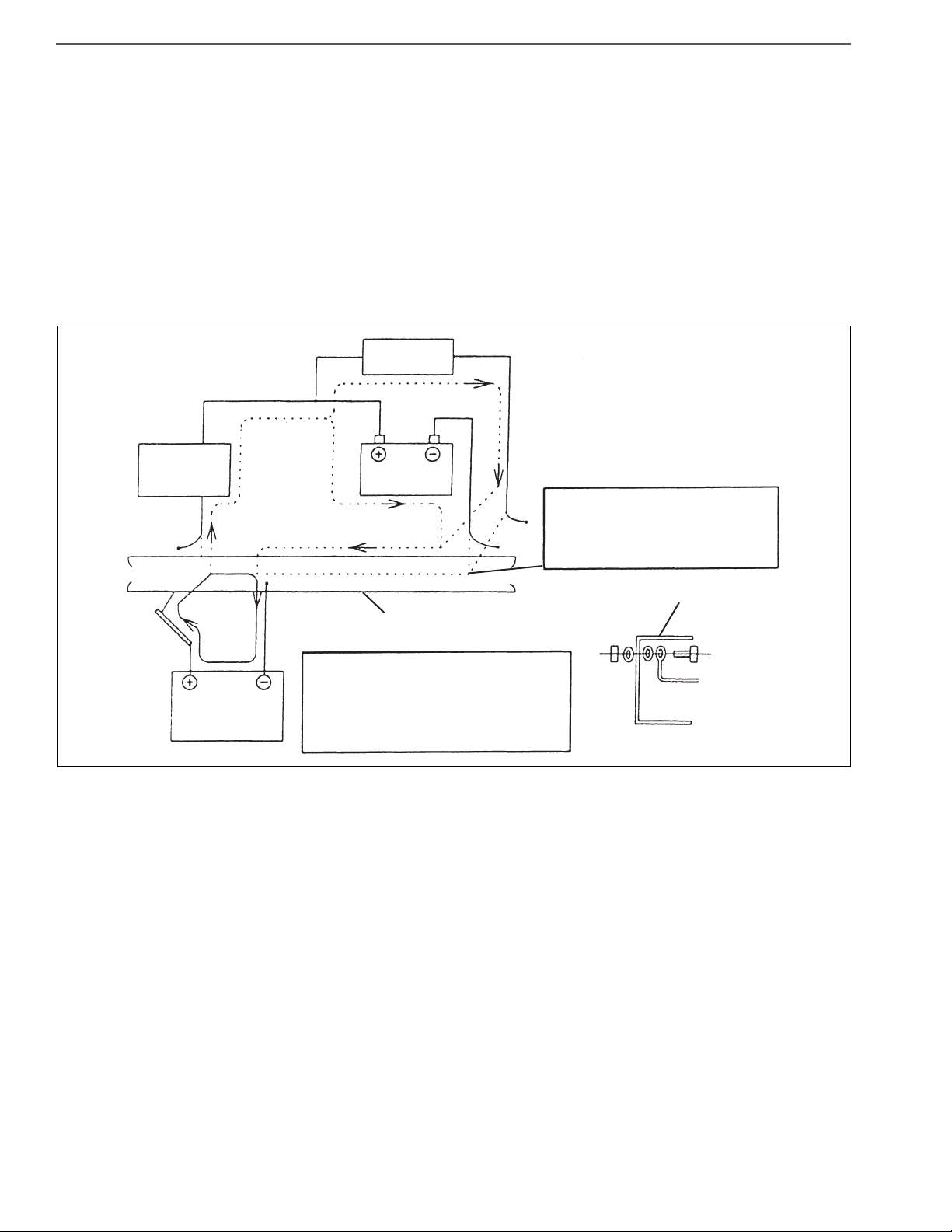
Connect the ground of the ARC welding
machine near the place on the frame to be
welded but not connect it to plated parts such
as fuel pipes, brake pipes and leaf spring.
Disconnect the ground terminal for
battery at the connecting point on the
frame and disconnect the ground for
computer as well.
Chassis frame
Chassis frame
Battery
Alternator
etc
Computer
ARC welding
machine
SHTS01ZZZ0300018
2. PRECAUTION FOR ELECTRIC WELDING
Electrical components such as the alternator and tachograph are directly connected to the battery and one
end is earthed to the chassis frame. Under these conditions, welding current will flow back along the earth
circuit if electric welding is carried out and damage may be caused to the alternator, tachograph, electrical
components, etc. Consequently, the following precautions are always to be taken during welding.
(1) Disconnect the earth terminal of the battery at the frame fitment and earth the welding equipment securely to the
frame itself. (Do not fit the welding equipment earth to such things as the tire rims, brake pipes or fuel pipes and
leaf spring, etc.)
a. Turn the starter switch off.
b. Disconnect the battery’s negative terminal of the battery.
c. Earth welding equipment securely, near to the area to be welded.
d. Put back battery negative ground as original condition.
e. Finally check the functioning of all instruments.
(2) In order to prevent damage to ancillary equipment components from sparks during welding, take steps such as
putting fire-resistant covers over things like the engine, meters, steering wheel, hoses, leaf spring and tires.

GENERAL INTRODUCTION/SAFETY INSTRUCTIONS AND READINESS TO WORK 1–17
GENERAL INFORMATION
INTRODUCTION TO WORKSHOP MANUAL
GENERAL
EN01H01ZZZ030102002001
1. SCOPE OF REPAIR DESCRIPTIONS
(1) There are three major processes in repair work: i.e. "trouble shooting", "removal/installation, replacement, over-
haul, assembly, inspection and adjustment" and "final inspection".
(2) This document covers only the first process (trouble shooting) and the second process (removal/installation,
replacement, overhaul, assembly, inspection and adjustment) and omits the third process (final inspection).
(3) The element tasks listed below are omitted from this document but must be done in actual repair work.
a. Jacking and lifting
b. Cleaning and washing of removed parts as required
c. Visual check
2. STANDARD VALUE
(1) Standard values, limits, required actions and tightening torques are tabulated in this document.
3. REQUIRED ITEMS
(1) Special tools, tools, instruments, oil and grease and other items to be prepared before starting work are listed in
the section titled "REQUIRED ITEMS". Note that general tools, jacks, rigid racks and other required items supposedly available at a general service shop are omitted from the list.
4. REPRESENTATION OF SECTION AND TITLE
(1) Under a title containing a system name such as "ENGINE CONTROL SYSTEM", the descriptions cover
"INSPECTION", "ADJUSTMENT", "REPLACEMENT" and "OVERHAUL" of components.
(2) Under a title containing a part name such as "AIR COMPRESSOR ASSEMBLY", the descriptions cover
"REPLACEMENT" and "OVERHAUL".

GENERAL INTRODUCTION/SAFETY INSTRUCTIONS AND READINESS TO WORK1–18
SHTS01ZZZ0300019
A possible cause and remedy/prevention are indicated for
every item, respectively.
INTRODUCTION TO DESCRIPTIONS
1. TROUBLE SHOOTING FOR EACH TROUBLE SYMPTOM WITH REFERENCE TO THE CHART
EN01H01ZZZ030102002002

GENERAL INTRODUCTION/SAFETY INSTRUCTIONS AND READINESS TO WORK 1–19
2. INTRODUCTION TO TROUBLE SHOOTING
(1) This document covers the trouble shooting steps 2 and 3 listed below.
(1) Hearing "Step 1"
(2) Prior check
(3) Reproducing technique
(4) Trouble shooting for each
diagnosis code
(5) Trouble shooting for each
trouble symptom
(6) Verification test "Step 4"
(2) Prior check
"Step 2"
"Step 3"
• Take the following prior check steps.
Diagnosis inspectiondiagnosis deletiontrouble symptom verification (use a reproducing
technique if not reproducible.)diagnosis recheck
• Prior to a reproduction test, identify a system suspected to have a trouble, attach a tester and
other apparatuses and then conduct both a symptom check and an examination on a sus-
Prior check
pected trouble. For a suspected cause of a trouble symptom, the trouble shooting chart.
• Instantaneous occurrence of a trouble symptom will also trigger a failure code. If no troubles
are observed, use a reproducing technique in performing each trouble shooting activity.
• Trouble symptom verification
If not reproducible, take the steps 2, 3 and 4.
If not reproducible, use a reproducing technique (e.g. adjust external conditions and inspect
each wire harness and connector part).
Identify a fact through adequate hearings on the situation
and environment where a trouble has occurred.
Conduct a diagnosis inspection, a symptom check, a functional inspection and a basic inspection to identify a symptom. If a symptom check does not gain enough
reproducibility, use a reproducing technique.
Sort the inspection results obtained from the step 2 and conduct an systematized inspection in accordance with the procedures for trouble shooting for each trouble symptom.
Verify that the same trouble will not occur after trouble shooting. If a trouble is not reproducible enough, conduct a verification test under the reproduced conditions and
environment.
GENERAL INTRODUCTION/SAFETY INSTRUCTIONS AND READINESS TO WORK1–20
ENGINE (COMMON ITEMS)/TROUBLESHOOTING2–466
INSPECTION PROCEDURE: P0606
1. Turn the starter key to the "LOCK" position.
2. Connect the diagnostic tester (HINO DX ൖ ) to the vehicle.
3. Turn the starter key to the "ON" position.
4. On the diagnostic tester screen, select [VCS] and check that no
vehicle speed signal-related DTC, P0501 or P0503, is detected.
NOYES
1. Inspect the CAN communication line.
NOYES
1
Reading DTC [HINO DX ൖ ]
SHTS029990300431
Is DTC P0501 or P0503 detected?
Perform troubleshooting for related DTC. Go to step 2.
2
Inspecting the CAN communication line
Is any defect found?
Repair or replace the CAN communication
line.
Replace the vehicle control ECU.
SHTS01ZZZ0300020
3. INTRODUCTION TO TROUBLE SHOOTING FOR EACH DIAGNOSIS MONITOR CODE
(1) The "diagnosis code list" and the "trouble shooting for each code" are contained in this document to address
each system for which a diagnosis monitor code will be output. If a diagnosis monitor code is already identified,
it is possible to immediately proceed with a trouble shooting process based on the code list.

GENERAL INTRODUCTION/SAFETY INSTRUCTIONS AND READINESS TO WORK 1–21
DEFINITION OF TERM
DEFINITION OF TERM
Terms used in this document are defined as follows.
DIRECTION
1. CHASSIS RELATED
(1) Longitudinal direction
a. The forward direction and the reverse direction of a vehicle are respectively defined as front and rear in the
installed position in a vehicle.
(2) Rotational direction
a. The clockwise direction and the counterclockwise direction viewed from the rear side of a vehicle are defined
as right-handed and left-handed respectively.
(3) Vertical direction
a. The upward direction and the downward direction in the installed position in a vehicle are defined as an upper
side and a lower side respectively.
(4) Lateral direction
a. The leftward direction and the rightward direction viewed from the back of a vehicle are respectively defined as
a left side and a right side in the installed position in a vehicle.
2. INDIVIDUAL DEVICES
(1) Longitudinal direction
a. The input side and the output side of motive power are defined as a front side and a rear side respectively.
(2) Rotational direction
a. The clockwise direction and the counterclockwise direction viewed from the back side are defined as right-
handed and left-handed respectively.
(3) Vertical direction
a. The upward direction and the downward direction of a device in its installed position in a vehicle (chassis) are
defined as an upper side and a lower side respectively.
(4) Lateral direction
a. The leftward direction and the rightward direction as viewed from the back side are defined as a left side and a
right side respectively.
EN01H01ZZZ030102002003
STANDARD VALUE
Represents a basic dimension (excluding a tolerance), and a clearance arising from tolerances when two parts are assembled.
REPAIR LIMIT
Represents a numerical value indicating need of correction. A symbol "+" or "-" indicated next to a repair limit represents
an increase or a decrease from a standard value.
SERVICE LIMIT
Represents a numerical value indicating need of replacement. A symbol "+" or "-" indicated next to a repair limit represents
an increase or a decrease from a standard value.
GENERAL INTRODUCTION/TROUBLE SHOOTING1–22
!CAUTION
SHTS01ZZZ0400001
TROUBLE SHOOTING
TROUBLESHOOTING WITH DIAGNOSIS MONITOR
DLC3
TC TS
CG
TROUBLESHOOTING PROCEDURE
EN01H01ZZZ040301002001
NOTICE
• Before reading the diagnosis code, turn the starter key to "ON"
and check that the check engine warning light comes on.
• Inspection is not available in check mode.
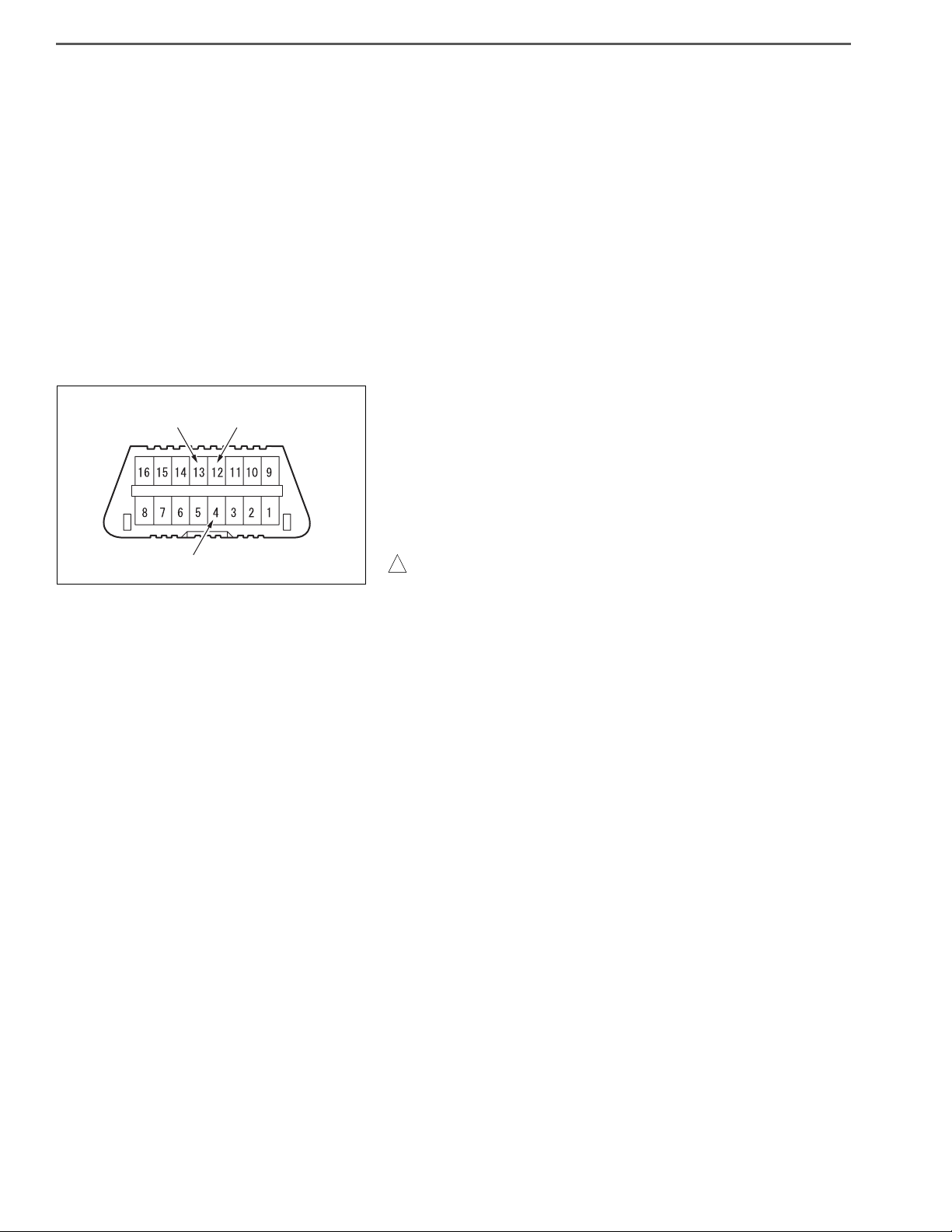
1. CONNECTION OF DIAGNOSIS CHECK WIRE
(1) Turn the starter key to the "LOCK" position.
(2) Use a SST to short circuit DLC3 12(TS) or 13(TC) 4(CG)
terminals.
SST: 09843-18040
Diagnosis check wire
HINT
The terminals to be shorted vary depending on the device to be
diagnosed.
• Never fail to connect connectors to correct locations. Other
wise failure may occur.
• Use the dedicated diagnosis check wire.
GENERAL INTRODUCTION/TROUBLE SHOOTING 1–23
The operation is repeated
Light ON
Light OFF
Indication of diagnosis monitor code (example)
When codes 32 and 21 are indicated:
0.5 second 0.5 second
1.5 second
4.3 second
Code 21
Code 32
When the system is normal
0.3 second
Light ON
Light OFF
SHTS01ZZZ0400002
2. INDICATION OF DIAGNOSIS MONITOR CODE
(1) A diagnosis monitor code can be identified by viewing the
diagnosis monitor and the check engine light. The example
shown below represents how to identify diagnosis monitor
codes 32 and 21. Intervals between light flashings will identify a diagnosis monitor code. For the first code, the number
"3" in the ten's place of the first code will be represented by
three 0.5-second flashings, followed by an interval of 1.5 seconds. Then, the light will flash twice. For the next code, after
an interval of 4.3 seconds, two flashings will be followed by
one flashing in the similar fashion to the first code. This flashing pattern will be repeated. If no system malfunctions are
detected, the light will repeat a 0.3-second flashing pattern.
NOTICE
As individual systems have different diagnosis monitor code outputting patterns, follow the descriptions provided for each system.
HINT
• This figure indicates a typical indication of diagnosis monitor
codes. For details, refer to the descriptions provided for individual systems.
• If no malfunctions are detected, the "diagnosis monitor code 1"
will be indicated.
• Malfunction codes will be repeatedly output in the ascending
order regardless of present or past malfunction codes.
HINT
• If no code is indicated (light not flashing), it is suspected that
the TC or TS terminal line is broken or the computer is faulty.
• If the check engine warning light is always on, it is suspected
that the wire harness is shorted (for example, jammed) or the
computer is faulty.
• If any meaningless code is out, the computer is suspected of
being faulty.
GENERAL INTRODUCTION/TROUBLE SHOOTING1–24
Dedicated harness (S0963-02300)
12
34
5
6
7
8
10
9
11
12
SHTS01ZZZ0400003
•
If the check engine warning light is lit and no code is output at
1,000 r/min or more, once turn the starter key to "LOCK" and
then recheck.
(2) Release DLC3 12(TS) or 13(TS) 14(CG) terminals.
APPARATUS FOR TROUBLE SHOOTING
1. TAG CODE AND SYSTEM NAME LIST FOR DEDICATED HARNESS
No. Tag name Name of system to be diagnosed
1 STD: ENG Common rail
3 STD: AIR BAG Not used
5 STD: ABS/ASR ABS
7 STD: ES START Not used
10 STD: VSC Not used
11 STD: TIRE Not used
2 OPT: RTD/4WD Not used
4 OPT: SHAKAN Not used
6 OPT: AIR SUS Not used
8 OPT: IDL STOP Not used
9 OPT: ATM Not used
EN01H01ZZZ040301002002
12 OPT: PRO SHIFT Not used
GENERAL INTRODUCTION/TROUBLE SHOOTING 1–25
SHTS01ZZZ0400004
Trouble diagnosis connector
SHTS01ZZZ0400005
TROUBLE DIAGNOSIS USING THE COMPUTER (HINO DX Ⅱ )
STEP OF TROUBLE DIAGNOSIS
EN01H01ZZZ040301003001
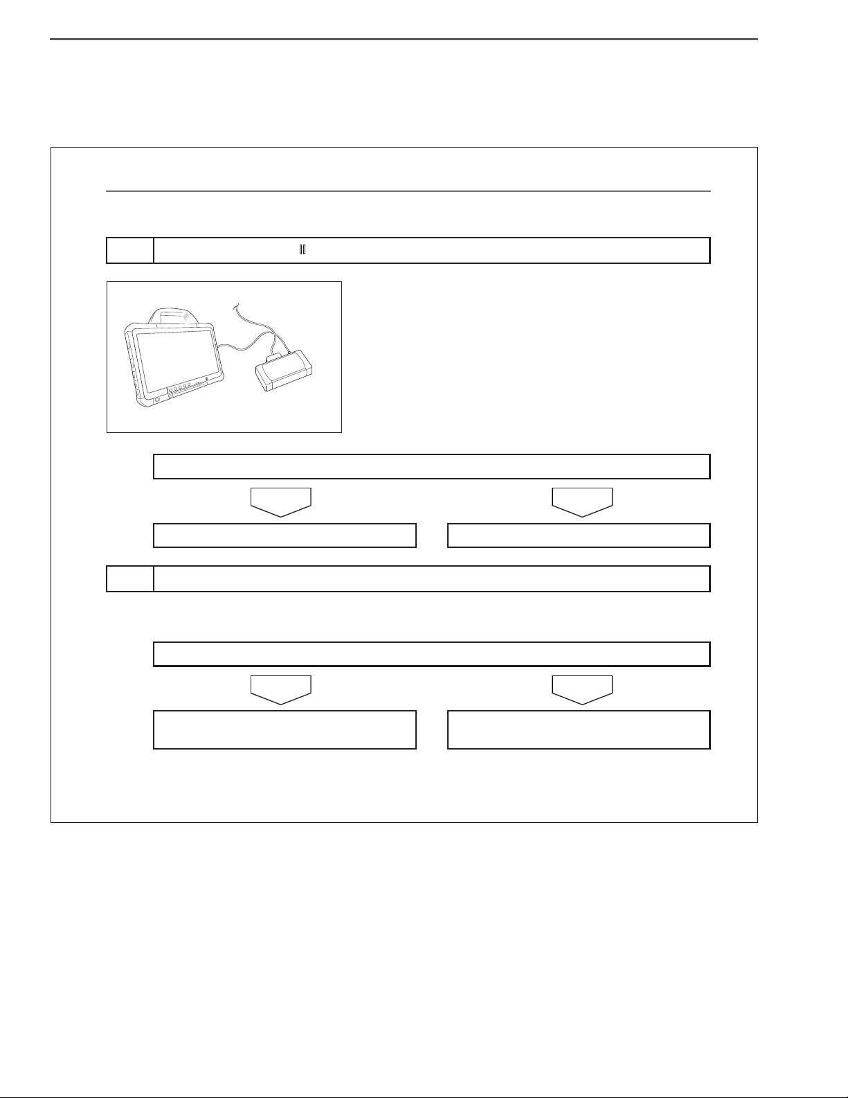
1. PREPARATION FOR CONNECTING HINO DX Ⅱ
(1) The "HINO DX Ⅱ " is a failure diagnosis tool for the common
rail fuel injection system and the chassis system. For connecting the computer to a vehicle, the "DST-i" and the dedicated cable will be required.
SPECIAL TOOL: Computer interface
Part name Part No.
DENSO DST-i Set
(Without LCD)
DENSO DST-i Set
(With LCD)
HINT
Install the "Hino Diagnostic eXplorer Ⅱ " (HINO DX Ⅱ ) software in a
computer. For detailed installation procedures, refer to the HINO
DX Ⅱ OPERATION MANUAL supplied on the Global Service Portal
Site (Hino-GSPS).
Without Bluetooth 95171-01021
With Bluetooth 95171-01041
Without Bluetooth 95171-01031
With Bluetooth 95171-01051
2. CONNECTION OF HINO DX Ⅱ
(1) Connect the DST-i to the trouble diagnosis connector located
in the electrical component box in the instrument panel or
located in the electrical component box behind the rearmost
seat.
(2) Connect the computer in which the HINO DX Ⅱ is installed, to
the DST-i.
(3) Turn the starter key to "ON".
(4) Turn on the power switch of the computer to start the HINO
DX Ⅱ .
GENERAL INTRODUCTION/TROUBLE SHOOTING1–26
APPARATUS FOR TROUBLE DIAGNOSIS
1. APPARATUS FOR TROUBLE DIAGNOSIS
Part name Part No. Illustration of appearance Outline/function
Laptop computer*
DENSO DST-i Set
(without LCD)
1
—
Without Bluetooth
95171-01021
With Bluetooth
95171-01041
The following specifications are necessary for operation of HINO DX Ⅱ .
• Operating system (OS): Windows7
Professional 32 bit.
• Browser: Microsoft Internet Explorer
8.0, 9.0
• CPU: 32 bit processors more than
1GHz.
• Memory: More than 1Gbyte.
• HDD: More than 100Gbyte.
Computer interface
These parts are supplied by DENSO Distributor.
EN01H01ZZZ040301003002
DENSO DST-i Set
(with LCD)
Signal check harness
Without Bluetooth
95171-01031
With Bluetooth
95171-01051
09843-E4050
(For engine ECU)
09843-E9030
(For DCU)
Red
Blue
Inserting this harness between the ECU
and the harness of the vehicle, you can
diagnose the ECU using tester rods with-
Engine
ECU
Black
E
E
V
White
V
out cutting off the power.
—
1
): Complete function of HINO DX Ⅱ is confirmed on "Panasonic CF-D1".
(*
 Loading...