

Page 1
NEST
FR52202ORB
Bulbs: 75 W MED. Replacemnt parts: GLASS: R52202GL-FRT, R52202GL-END
ASSEMBLY INSTRUCTIO N S
Assembly of this fixture will be accomplished by first installing the mounting strap to
the junction box
, mounting the fixture to the wall and then installing the glass.
SAFETY WARNING: Read wiring and grounding instructions [FRIS 18]
and any additional directions. Turn power supply off during installation. If new wiring
is required, consult a qualified electrician or local authorities for code requirements.
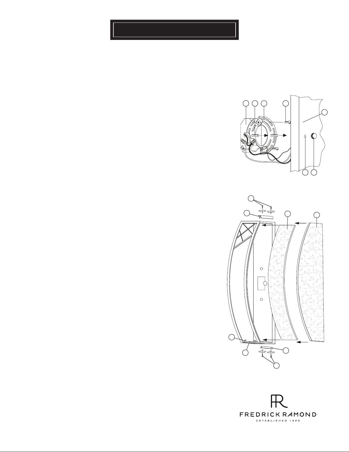
STEP 1
1 Prepare mounting strap (a) by threading the two longest mounting screws (b)
into the back of the mounting strap (a), making sure the holes into which the
screws are threaded match the spacing of holes (d) in the backplate (e) - See
Drawing 1.
2 Attach mounting strap (a) to junction box (j) using two screws (c).
3 Make electrical connections from supply wire to fixture lead wires. Refer to
instruction sheet [FRIS18] and follow all instructions to make all necessary
wiring connections. Then refer back to this sheet to continue installation of
this fixture.
4 To mount fixture, slip the two mounting screws (b) through the two mounting
holes (d) in the backplate (e).
5 While holding fixture in place, thread the two ball knobs (f) on to the end of the
mounting screws (b), and tighten.
j
b
1
2
[DRAWING 1 ]
a c
[DRAWING 2]
3
e
f
d
6
STEP 2
1
To install glass it is first neccesary to remove the two screws (1) that hold each
of the four brackets (2) in place on the top and bottom of the fixture
cage assembly. All screws and brackets should be set aside in a safe place
to use later.
Install the arched front panel (3) by sliding it in and in front of the glass
2
clips (4) located behind uprights (5).
Attach the brackets (2) removed from the bottom of the fixture earlier. Do
3
not tighten the screws at this time. Leave brackets loose.
4
Slip bottom end of one side panel (6) behind bottom bracket (2) and tilt
panel upward into position. Hold panel in position and attache top bracket
(2) with screws (1) removed earlier. Screw in top and bottom brackets can
now be tightened.
5
Lamp fixture accordingly prior to installing last side panel (6).
6
Install last side panel by following the same procedures outlined above in
line 4.
4
5
800.42 1. 35 17 WW W.F RE DR IC KR AMON D.C OM
2
1
01.01.10
 Loading...