

Page 1
CARABEL
FR44622BC H
Bulbs: 100W MED.
A S S E M B LY INSTRU CTION S
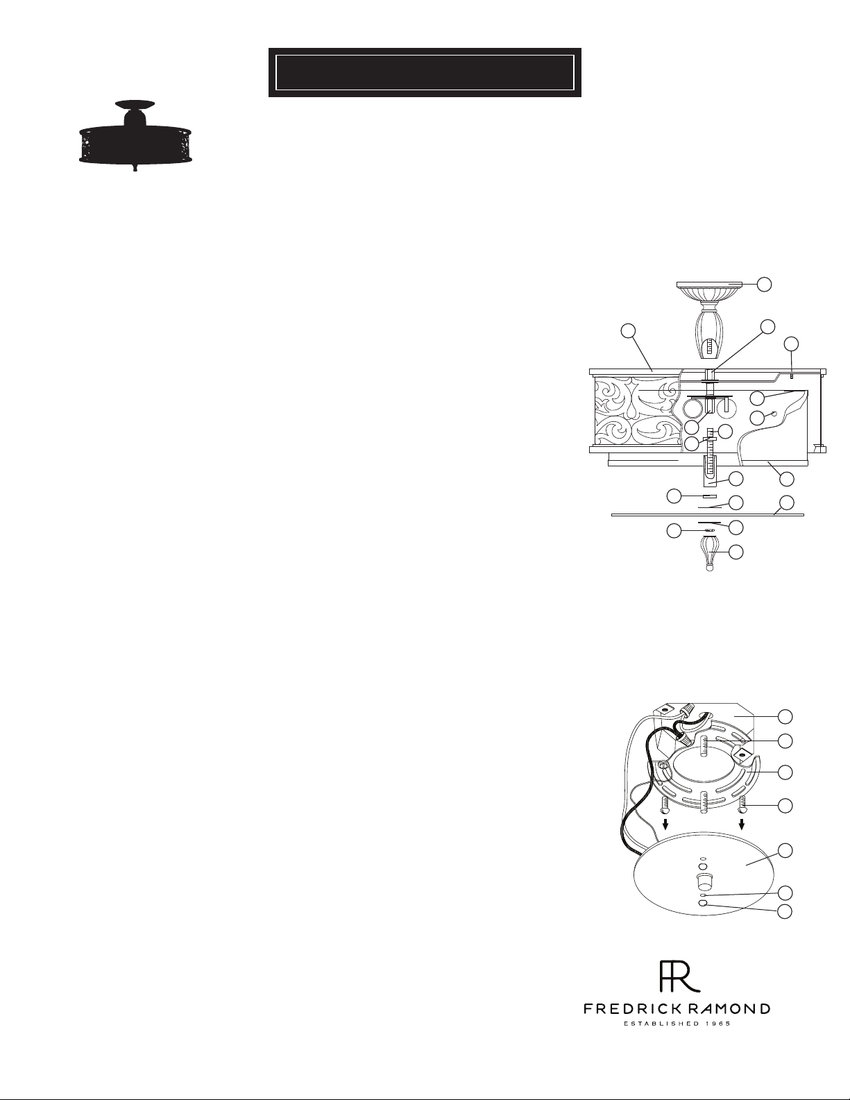
Assembly of this fixture will be accomplished by first assembling the main body,
installing the mounting hardware to the junction box, making all necessary electrical
connections and then hanging the fixture.
[DRAWING 1]
1
SAFETY WA RNING: Read wiring and grounding instructions
and any additional directions. Turn power supply off during installation. If new wiring
is required, consult a qualified electrician or local authorities for code requirements.
[FRIS 18]
STEP 1
1
Slip center column (1) along wire and thread onto coupler (a).
2
3
shade tab with stud (c) on cage arms.
5
approximately 3/8”.
followed by rubber washer (9). Rubber washer will hold parts in position.
Remove ball knob (2) from stud (c) located on arm of cage (4).
Slip shade (3) into the cage assembly (4). Making sure to line up holes (b) in
Thread ball knob (2) onto end of stud (c) to secure shade. 4
Thread stem (5) into coupler (d) located in the center of the socket assembly,
Slip cap (6) flat part up, onto stem (5) followed by tube (7) and hold in position. 6
Slip bottom cap (8) flat side down, onto stem (5) and over end of tube (7),
7
Fixture can now be lamped accordingly.
8
9
Slip steel washer (11) onto stem (5), then thread hex nut (12) onto stem (5) and tighten
to secure glass lens.
10
Thread finial (13) onto end of exposed stem (5) to complete assembly.
Slip glass lens (10) onto stem (5) and hold in position.
-
See Drawing 1.
S TEP 2
1 Prepare mounting strap (a) by threading the two long mounting screws (b)
into the back of the mounting strap (a), making sure the holes into which the
screws are threaded match the spacing of holes (d) in the backplate (e) - See
Drawing 1.
2 Attach mounting strap (a) to junction box (j) using two screws (c).
3 Make electrical connections from supply wire to fixture lead wires. Refer to
instruction sheet [FRIS18] and follow all instructions to make all necessary
wiring connections. Then refer back to this sheet to continue installation of
this fixture.
4 To mount fixture, slip the two mounting screws (b) through the two mounting
holes (d) in the canopy (e).
5 While holding fixture in place, thread the two ball knobs (f) on to the end of the
mounting screws (b), and tighten.
4
8
12
[DRAWING 2]
a
c
b
d
6
2
5
7
9
11
13
3
10
j
b
a
c
e
d
f
800. 421.35 17 WWW .F RE DR ICKRA MON D. CO M
12.1.09
 Loading...