

Page 1
IMPULSE IMPULSE IMPULSE
Item No. 44413 Numéro d’article: 44413
Bulbs: LED replacement parts: Bulbos: LED piezas de recambio: Ampoules: LED pièces de rechange:
ASSEMBLY INSTRUCTIONS
Assembly of the fixture will be accomplished by first installing the
mounting hardware, making all necessary electrical connections, mounting
mnain body to the ceiling, installing fixture arms, then attaching the acrylic
lens.
SAFETY WARNING: Read wiring and grounding instruction [FRIS 18]
and any additional directions. Turn power supply off during installation.
if new wiring is required, consult a qualified electrician or local authorities
for code requirements.
STEP 1
1. It is recommended to first mount the main body (a) to the ceiling - see
Drawing 1.
english spanish
Número del artículo: 44413
INSTRUCCIONES DE MONTAJE
Asamblea de la fijación se realizará mediante la instalación de la
primera accesorios de montaje , por lo que todas las conexiones
eléctricas necesarias , montaje el cuerpo principal del techo , la
instalación de brazos accesorios , y luego fijar el acrílico lente .
SEGURIDAD ADVERTENCIA: Lea el cableado y conexión a tierra
de instrucciones [ FRIS 18 ] y cualquier instrucción adicional.
Cortar el suministro eléctrico durante la instalación. si se necesita
un nuevo cableado , consulte a un electricista calificado o con las
autoridades locales de los requisitos del código .
PASO 1
1 . Se recomienda primero montar el cuerpo principal (A) para el
techo - ver Dibujo 1 .
INSTRUCTIONS DE MONTAGE
Assemblée de l'appareil sera effectuée par la première installation de l'
matériel de montage , toutes les connexions électriques nécessaires , le
montage le corps principal au plafond , l'installation de bras de fixation ,
puis fixer le acrylique lentille .
SÉCURITÉ AVERTISSEMENT: Lire le câblage et la terre instruction
[ FRIS 18 ] et des instructions supplémentaires . Couper l'alimentation
électrique pendant l'installation. si nouveau câblage n'est nécessaire ,
consulter un électricien qualifié ou les autorités locales pour les exigences
du code .
ÉTAPE 1
1 . Il est recommandé de commencer par monter le corps principal
( a) au plafond - voir Dessin 1 .
french
[DRAWING 1]
a
b
p
r
2. This is accomplished by follow instruction sheet [FRIS35000] provided.
STEP 2
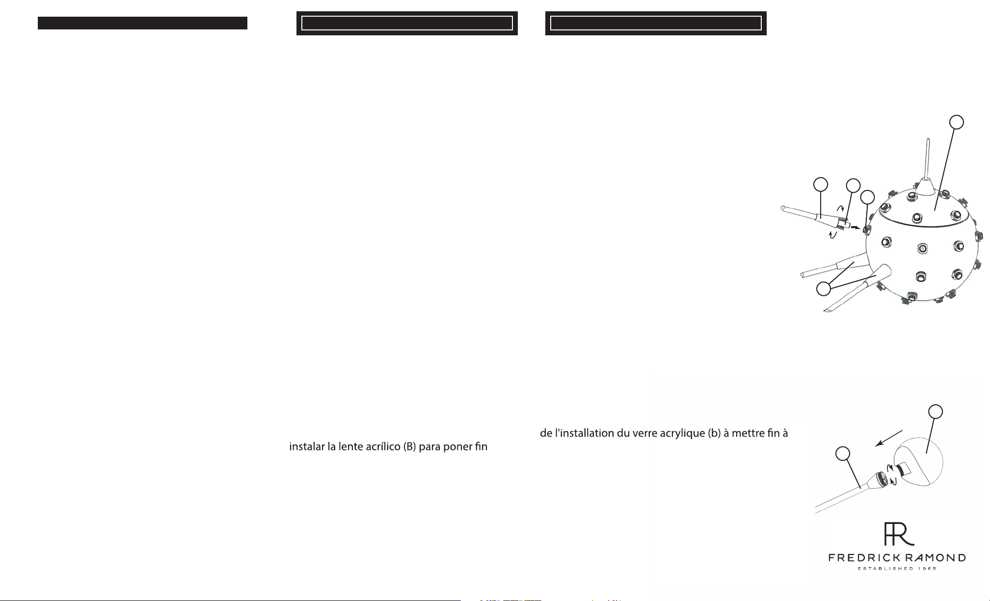
1. After main body (a) is installed the arms (b) can be attached by slipping
pin (p) into receptacle (r) located on main body (a) and then threading the
arms onto main body - see Drawing 1.
NOTE: please take caution when threading arm on main body. So arms are
not cross threaded onto receptacle (r).
2. After all arm are attached to the main body the acrylic lens (l) can be
threaded onto end of arm (b) - see Drawing 2.
CAUTION: Make sure hands are clean and free of
oil or dirt when installing the acrylic lens (b) to end
of arm.
2 . Esto se logra mediante la hoja de instrucciones de seguimiento
[ FRIS35000 ] proporcionó .
PASO 2
1 . Después cuerpo principal ( a) se instala los brazos ( b ) se puede
conectar por el deslizamiento pasador ( P) en el receptáculo ( R )
situado en el cuerpo principal ( A) y después enroscando el brazos
hacia curepo principal - ver Dibujo 1 .
NOTA : por favor, tenga cuidado cuando esté pasando el brazo sobre
el cuerpo principal. Así que los brazos no soncruzar roscada sobre
el receptáculo ( R ) .
2 . Después de todo el brazo se une al cuerpo principal de la lente
de acrílico ( L ) puede ser roscado en el extremo del brazo ( b )
- ver dibujo 2 .
PRECAUCIÓN: Asegúrese de que las manos
están limpias y libres de aceite o suciedad al
del brazo.
2 . Ceci est accompli par la feuille d'instruction de suivi [ FRIS35000 ]
fourni .
ÉTAPE 2
Une . Après corps principal ( a) est installé, les bras ( b ) peut être
fixé par glissement broche ( p) dans le réceptacle (r ) situé sur le
corps principal (a ), puis d'enfiler le bras sur corps principal - voir schéma 1 .
REMARQUE : s'il vous plaît prendre des précautions lors de l'enfilage
bras sur le corps principal . Ainsi, les bras ne sont pas traverser fileté
sur réceptacle ( r ) .
2 . Après tout bras sont fixés au corps principal de la lentille acrylique ( l)
peut être filetée sur l'extrémité du bras ( b ) - voir schéma 2 .
ATTENTION: Assurez-vous que vos mains sont
propres et exempts de l'huile ou de la saleté lors
du bras.
b
[DRAWING 2]
l
b
01.01.14
A Division of Hinkley Lighting Inc.
33000 PIN OAK PARKWAY | AVON LAKE, OHIO 44012
toll free 800.446.5539 | phone 440.653.5500
Page 2
FRIS 35000 FRIS 35000 FRIS 35000
english spanish
[DRAWING 1]
french
START HERE
SAFETY WARNING: READ WIRING AND GROUNDING INSTRUCTIONS
[FRIS 18]. TURN POWER SUPPLY OFF DURING INSTALLATION. IF
NEW WIRING IS REQUIRED, CONSULT A QUALIFIED ELECTRICIAN OR
LOCAL AUTHORITY FOR CODE REQUIREMENTS.
1. Find a clear area to work.
2. Unpack fixture from carton.
3. Carefully review instructions prior to assembly.
This fixture is designed to be directly mountined to a ceiling junction box
with a 3-1/2” center to center mounting distance.
Fixture Mounting - see Drawing 1.
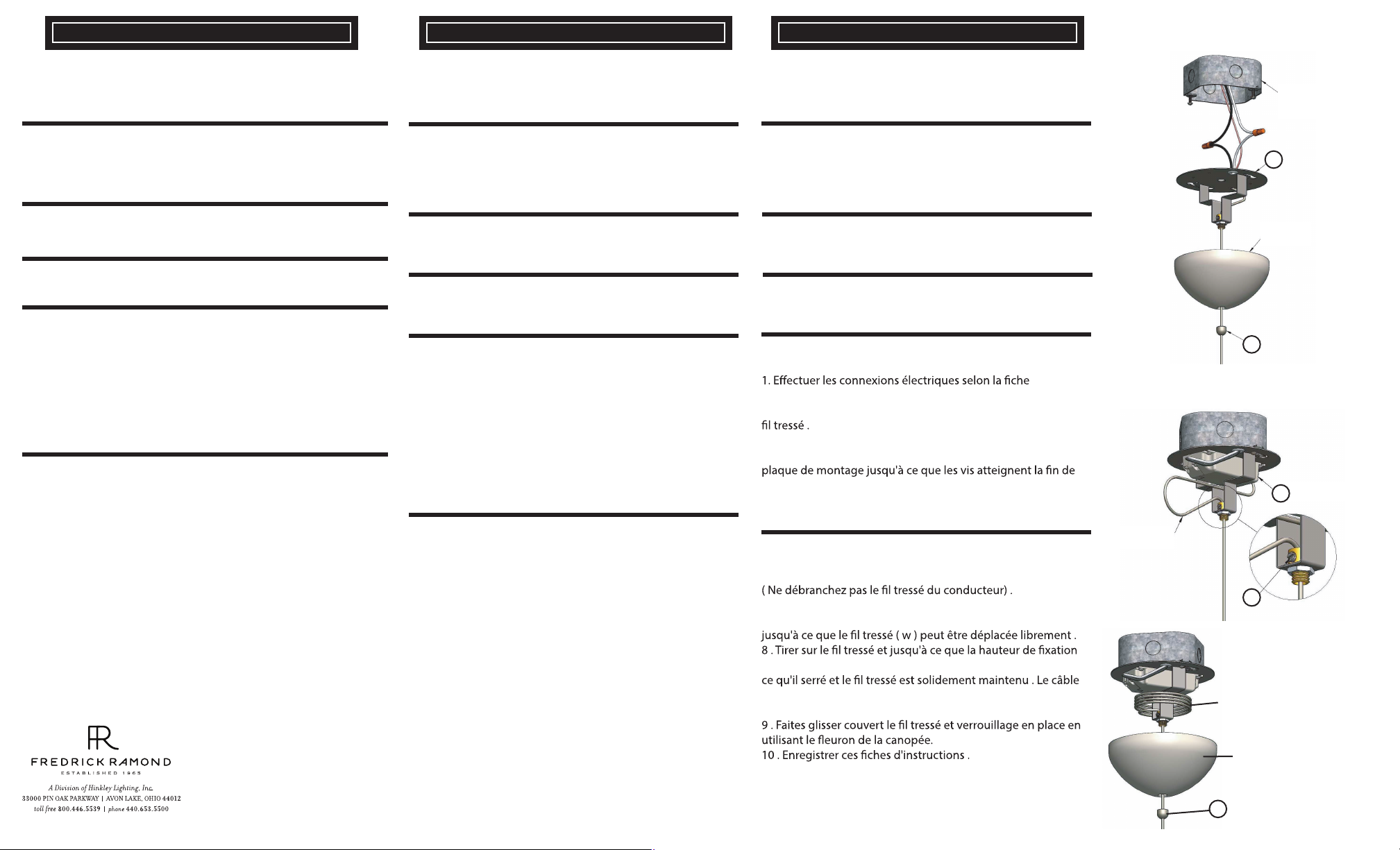
1. Make electrical connections according to instruction sheet [FRIS 18].
2. Unthread caonpy finial (a) and slide canopy down wire.
3. Keyhole slots in Mounting Plate (b) should fit over screws that came
with junction box. Turn mounting plate (b) until the screws reach the
end of the slot.
4. tighten screws until snug.
5. Proceed to fixture adjustment instructions
Fixture Adjustment - see Drawing 2
6. Fixture is completely wired to the driver (DO NOT DISCONNECT THE
BRAIDED WIRE FROM THE LED DRIVER).
7. Using a flat bladed screw driver turn the set screw (c) in a counter
clockwise direction until the braided wire moves freely.
8. Pull braided wire up and out until the desired fixture height is reached.
Tighten set screw (c) just till snug and the braided wire is held securely.
Extra wire can be wrapped aroung the mounting bracket.
9. Slide canopy up the braided wire and lock in place using the canopy
finial.
10. Save these instruction sheets.
EMPIEZA AQUÍ
ADVERTENCIA DE SEGURIDAD : LEA INSTRUCCIONES DE
CABLEADO ( Fris 18 ) . APAGUE LA FUENTE DE ALIMENTACIÓN
DURANTE LA INSTALACIÓN. SI NUEVO CABLEADO SE
REQUIERE , CONSULTE CON UN ELECTRICISTA O AUTORIDAD
LOCAL PARA REQUISITOS DEL CÓDIGO .
1 . Busque un lugar claro para trabajar .
2 . Desembale aparato de la caja de cartón.
3 . Revise cuidadosamente las instrucciones antes del montaje .
Este aparato está diseñado para ser montado directamente a una caja
de conexiones del techo con un centro de 3-1/2 "para centrar
distancia de montaje .
Accesorio de montaje - ver dibujo 1 .
1 . Haga las conexiones eléctricas de acuerdo con la hoja de
instrucciones [ FRIS 18 ] .
2 . Desenrosque Canopy Finial ( a) y la cubierta deslizante de alambre
trenzado abajo .
3 . Ranuras en la placa de montaje (B ) deben caber por sobre
tornillos que vienen con la caja de conexiones . Girar la placa de
montaje hasta que los tornillos alcanzan el final de la ranura .
4 . Apriete los tornillos hasta que estén ajustados .
5 . Proceder al accesorio instrucciones de ajuste
Ajuste Fixture - ver dibujo 2 :
6 . La instalación está completamente conectado al conductor del
LED ( d ) ( NO DESCONECTE EL CABLE TRENZADO DEL
CONDUCTOR ) .
7 . Con un destornillador de punta plana gire el tornillo de ajuste ( c )
en el sentido contrario a las agujas del reloj hasta que el cable
trenzado ( w ) se puede mover libremente.
8 . Tire de alambre trenzado arriba y hacia afuera hasta que se alcance
la altura deseada fixture . Apriete el tornillo de fijación ( c ) sólo hasta
que calce y el cable trenzado se mantiene de forma segura . El cable
extra se puede envolver alrededor del soporte de montaje.
9 . Deslice de campana hasta el alambre trenzado y bloqueo en su
lugar con el remate del dosel .
10 . Guarde estas hojas de instrucciones .
COMMENCEZ ICI
AVERTISSEMENT DE SÉCURITÉ : LIRE RACCORDEMENT ET MISE À
LA TERRE ( FRIS 18 ) . COUPER L'ALIMENTATION ÉLECTRIQUE
PENDANT L'INSTALLATION. SI DE NOUVELLES CÂBLAGE N'EST
NÉCESSAIRE , CONSULTER UN ÉLECTRICIEN QUALIFIÉ OU UNE
AUTORITÉ LOCALE POUR LES EXIGENCES DE CODE .
1. Allez dans un endroit pour travailler .
2 . Déballez projecteur du carton .
3 . Lire attentivement les instructions avant l'assemblage .
Cet appareil est conçu pour être monté directement sur une boîte
de jonction de plafond avec un centre de 3-1/2 "pour centrer
distance de montage .
Mobilier de montage - voir schéma 1 .
d'instruction [ FRIS 18 ] .
2 . Dévissez Canopy Fleuron ( a) et faites glisser vers le bas couvert
3 . Trous de serrure dans la plaque de montage ( b ) doivent
s'inscrire sur les vis fournies avec la boîte de jonction . Tournez la
la fente .
4 . Serrer les vis à fond.
5 . Procéder au montage des instructions d'ajustement
Réglage de la Mobilier - voir schéma 2 :
6 . Appareil est complètement câblé au conducteur de LED (d )
7 . L'utilisation d'un tournevis à lame plate , tournez la vis de
réglage ( c ) dans le sens inverse des aiguilles d'une montre
souhaitée est atteinte . Serrer la vis de réglage ( c ) juste jusqu'à
supplémentaire peut être enroulé autour du support
de montage.
CEILING
JUNCTION
BOX
b
CANOPY
a
[DRAWING 2]
d
c
DETAIL 1
EXTRA BRAIDED
WIRE
CANOPY
a
01.01.14
Page 3

FRIS18
TIERRA CABLEADO INSTRUCCIONES
Advertencia De Seguridad: Lea las Instrucciones de cableado y conexión a tierra [FRIS 18], e
instrucciones adicionales. Encienda la alimentación de corriente durante la instalación. Si se necesita un
nuevo cable, consulte a un electricista calificado o con las autoridades locales de los requisitos del código.
PASO 1 INSTRUCCIONES DE CABLEADO
Accesorios Cubierta
1. Conecte el cable de alimentación positive (A) (normalmente negro o la cara
lisa, sin marcas del ceable de dos conductores) de plomo accesorio positivo
(B) con un giro de tamaño adecuado en el conector – Véase la Figura 1 o 2.
2. Conecte el cable de alimentación negative (C) (por lo general de color blanco
o el lado marcado estriado del cable de dos conductores) de plomo accesorio
negativo (D).
3. Por favor, consulte las Instrucciones de conexión a tierra de abajo para
completer todas las conexiones eléctricas.
Accesorios Exterior
1. Conecte el cable de alimentactión positive (A) (normalmente negro o la cara
lisa, sin marcas del cable de dos conductores) de plomo accesorio positivo
(B) con un giro de tamanño adecuado en el conector - Véase la Figura 1 o 2.
2. Conectar el cable de alimentación negative (C) (por lo general de color
blanco o el, lado marcado acanalada del cable de dos conductores) a plomo
acesorio negativo (D).
3. Cubra el extreme abierto de conectores con sellador de silicona para formar
un sello hermético.
• Si va a instalar un soporte de fijación mural, use masilla para sellar los
espacios entre la placa de montaje del aparato (placa) y la pared. Esto
ayudará a evitar que el agua entre en la caja de salida. Si la superficie de la
pared es de revestimeinto solapado, utilice masilla y una plataforma de
montaje accesorio espacial.
4. Por favor, consulte las Instrucciones de conexión a tierra a continuación
para completer todas las conexiones eléctricas.
PASO 2 INSTRUCCIONES PUESTA A TIERRA
Flush Mount Fixtures
Para conectar a tierra en un sistema eléctrico de 3 hilos, fije el cable de tierra
del artefacto (E) (generalmente de cobre o verde recubierto de plástico) a la
brida de montaje fijación (1) con el tornillo de tierra (2) – Véase la Figura 1.
Nota: En las correas de accesorios compatibles tornillos, primero instale los
dos tornillos de montaje de la correa.
Cualquier agujero roscado restante puede ser utilizado para el tornillo de tierra.
Chain Hung Fixtures
Loop alambre de tierra (E) (generalmente de cobre o verde recubierto de
plástico) debajo de la cabeza del tornillo de tierra (2) en la brida de montaje
fijación (1) y conecte el extremo suelto del cable de tierra luminaria
directamente al cable de tierra del sistema de construcción con un tamaño
adecuado twist conectores – Véase la Figura 2.
Post-Mount Fixtures
Conecte el cable de tierra del artefacto (E) (generalmente de cobre o verde
recubierto de plástico) a tierra de la fuente de alimentactión con conector de
tamaño adecuado en el interior puesto enlaces en forma. Cubra el extremo
abierto del conector con sellador de silicona para formar un sello hermético -
Véase la Figura 3.
FRIS18
CÂBLAGE ÉCHOUAGE INSTRUCTIONS
Avertissement De Sécurité: Lire câblage et de mise à la terre instructions [FRIS 18] et les
instructions supplémentaires. Couper l’alimentation électrique pendant l’installation. Si un nouveau câblage nést
nécessaire, consultez un ékectricien qualifié ou les autorités locales pour connaître les exigences du code.
ETAPE 1 INSTRUCTIONS DE CÂBLAGE
Luminaires Itérieurs
. Branchez le câble d’alimentation positive (A) (généralement noir ou, côté
1
lisse banalisée de la corde à deux conducteurs) au plomb de fixation positive
(B) avec la torsion de taille appropriée sur le connecteur - Voir Schéma 1 et 2
2. Raccorder le fil d’alimentation negative (C) (généralement blanc ou l’, côté
marqué nervurée du fil à deux conducteurs) au conducteur négatif de
l’appareil (D).
3. S’il vous plait se referrer aux instructions ci-dessous pour remplir la terre
toutes les connexions électriques.
Luminaires Extérieurs
1. Brancher le fil d’alimentation positive (A) (généralement noir ou, côté lisse
banalisée de la corde à deux conducteur) à plomb de fixation positive (B) avec
la torsion de taille appropriée sur le connecteur – Voir Schéma 1 ou 2.
2. Connecter le fil d’alimentation negative (C) (généralement blanc ou l’, côté
marqué nervurée du fil à deux conducteurs) au conducteur négatif de
l’appareil (D).
3. Couvrir extrémité ouberte de connecteurs avec du silicone pour former un
joint étanche à l’eau.
• Se l’installation d’un luminaire de montage mural, utiliser calfeautrage pour
sceller l’espace entre la plaque de montage de fixation (plaque arrière) et la
paroi. Cela aidera à emp6echer l’eau de pénétrer dans la boîte de sortie. Si la
surface du mur est bardage à clin, utiliser calfeautrage et une plate-forme de
montage d’appareils spécialement.
4. S’il vous plait se referrer aux instructions ci-dessous pour terminer la terre
toutes les connexions électriques.
ETAPE 2 INSTRUCTIONS DE MISE
Montage Encastré Fixtures
Pour la terre positive dans un système électrique à 3 fils, fixez le fil de terre du
luminaire (E) (généralement en cuivre ou vert recouvert de plastique) à la sangle
de fixation de fixation (1) avec la vis de terre (2) – Voir Schéma 1.
Remarque: Sur les sangles pour les appareils pris en charge à vis, installez
d’abord les deux vis de fixation à sangle.
Tout trou taraudé restante peut être utilisée pour la vis de terre.
Chaîne Accroché Luminaires
Boucle fil du luminaire au sol (E) (généralement en cuivre ou vert recouvert de
plastique) sous la tête de la vis de terre (2) sur la sangle de fixation de fixation
(1) et se connecter à l’extrémité libre du fil de terre du luminaire directement
sur le fil de terre du système de construction avec une taille appropriée
connecteurs à visser - Voir Schéma 2.
Luminaires Aprés Montage
Brancher le fil de terre du luminaire (E) (généralement en cuivre ou vert
recouvert de plastique) à la masse de l’alimentation avec une taille appropriée
torsion sur le conecteur à l’intérieur de la poste. Couvrir extrémité ouverte du
connecteur avec du mastic silicone pour former un joint ètache à l’eau – Voir
Schéma 3.
WIRING AND GROUNDING INSTRUCTIONS
Safety Warning: Read wiring and grounding instructions [FRIS 18] and any additional
directions. Turn power supply off during installation. If new wiring is required, consult a qualified electrician
or local authorities for code requirements.
STEP 1 WIRING INSTRUCTIONS
Indoor Fixtures
1. Connect positive supply wire (A) (typically black or the smooth, unmarked
side of the two-conductor cord) to positive fixture lead (B) with
appropriately sized twist on connector – See Drawing 1 or 2.
2. Connect negative supply wire (C) (typically white or the ribbed, marked side
of the two-conductor cord) to negative fixture lead (D)
3. Please refer to the grounding instructions below to complete all electrical
connections.
Outdoor Fixtures
1. Connect positive supply wire (A) (typically black or the smooth, unmarked
side of the two-conductor cord) to positive fixture lead (B) with
appropriately sized twist on connector – See Drawing 1 or 2.
2. Connect negative supply wire (C) (typically white or the ribbed, marked side
of the two-conductor cord) to negative fixture lead (D)
3. Cover open end of connectors with silicone sealant to form a watertight seal.
• If installing a wall mount fixture, use caulk to seal gaps between the fixture
mounting plate (backplate) and the wall. This will help prevent water from
entering the outlet box. If the wall surface is lap siding, use caulk and a
fixture mounting platform specially.
4. Please refer to the grounding instructions below to complete all electrical
connections.
STEP 2 GROUNDING INSTRUCTIONS
Montaje Embutido Accesorios
For positive grounding in a 3-wire electrical system, fasten the fixture ground
wire (E) (typically copper or green plastic coated) to the fixture mounting strap
(1) with the ground screw (2) – See Drawing 1.
Note: On straps for screw supported fixtures, first install the two mounting
screws in strap.
Any remaining tapped hole may be used for the ground screw.
Cadena Hung Accesorios
Loop fixture ground wire (E) (typically copper or green plastic coated) under
the head of the ground screw (2) on fixture mounting strap (1) and connect to
the loose end of the fixture ground wire directly to the ground wire of the
building system with appropriately sized twist-on connectors – See Drawing 2.
Accesorios Posterior Monte
Connect fixture ground wire (E) (typically copper or green plastic coated) to
power supply ground with appropriately sized twist-on connector inside post.
Cover open end of connector with silicone sealant to form a watertight seal –
See Drawing 3.
FRIS18
[DRAWING 1]
[DRAWING 2]
[DRAWING 3]
A Division of Hinkley Lighting Inc.
33000 PIN OAK PARKWAY | AVON LAKE, OHIO 44012
toll free 800.446.5539 | phone 440.653.5500
08.23.13
 Loading...