

Page 1
BARCELONA
FR44102
Bulbs: 60W CAN D. & 75W MED.
AS S E M BLY I N S T RUCTIONS
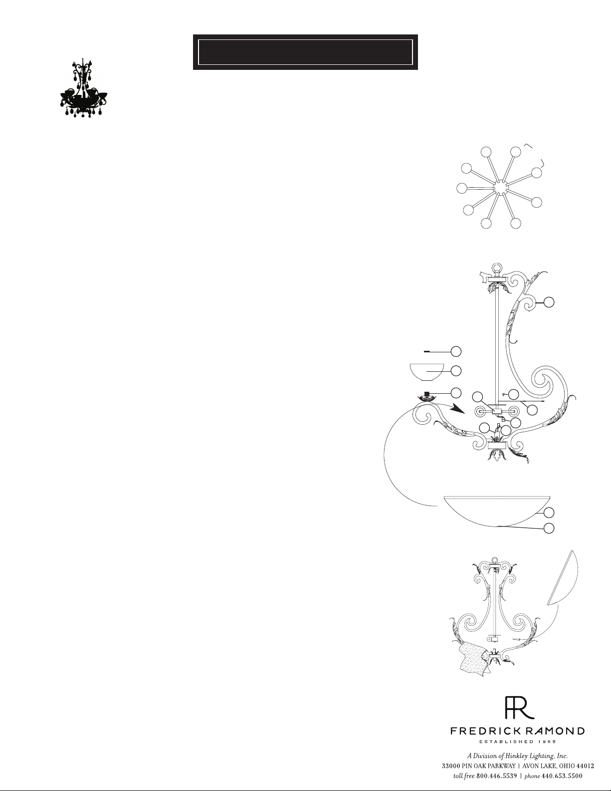
Assembly of this fixture will be accomplished by first spreading the arms to their
proper position, assembling the main body parts, hanging the fixture, installing
the glass and then attaching the crystals.
SAFETY WARNING: Read wiring and grounding instructions [FRIS 18]
and any additional directions. Turn power supply off during installation. If new wiring
is required, consult a qualified electrician or local authorities for code requirements.
S T EP 1
1 Take the main fixture assembly and spread the arms (a) until they are
approximately 40° apart - See Drawing 1.
[DRAWING 1]
a
a
a
a
a
[DRAWING 2]
40°
a
a
a
a
S T EP 2 Refer to Hanging Instruction Sheet [FRIS19-50R] to hang fixture. Then refer
back to this sheet to continue installation of this fixture.
S T EP 3
1 Remove threaded socket ring (1) from socket (c) - See Drawing 2.
2 Slip small alabaster bowl (2) over socket (c).
3 Thread socket ring (1) onto socket (c) to secure glass (2).
· The large natural alabaster bowls used on the Barcelona series can be scratched
during installation if care is not taken. To prevent scratching of the alabaster,
we suggest the following procedure.
4 Prior to inserting large bowl (3), take small hand towels and lay them over
each of the arms - See Drawing 3.
5 Tilt alabaster bowl up and slip lip of glass under uprights, being careful not to
damage the wires and quick connect (5) located in the bottom center of the
fixture.
Note: Make sure quick connect is passed through the center hole (d) of the
alabaster bowl (3) and the center hole also slips over the center pipe (e).
6 Plug quick connector (4) and (5) together.
Note: the connector is designed to fit only one way.
7 Fixture can now be lamped accordingly.
1
2
c
f
e
[DRAWING 3]
a
6
7
4
5
3
d
STEP 4
1 Remove the ball knob screws (6) located above the socket assembly (f)- See
Drawing 2.
2 Talk half of the perforated diffuser (7) and attach it above socket assembly (f)
using the ball knob screws (6) removed earlier.
3 Repeat steps 1-2 for opposite half of perforated diffuser (7), making sure the tabs
are engaged on the opposite diffuser half.
STE P 5 Refer to Crystal Installation Sheet provided to install crystals.
09.12.08
Page 2
BARCELONA
FR44102
Bulbs: 7 5W MED. Replacement Parts:
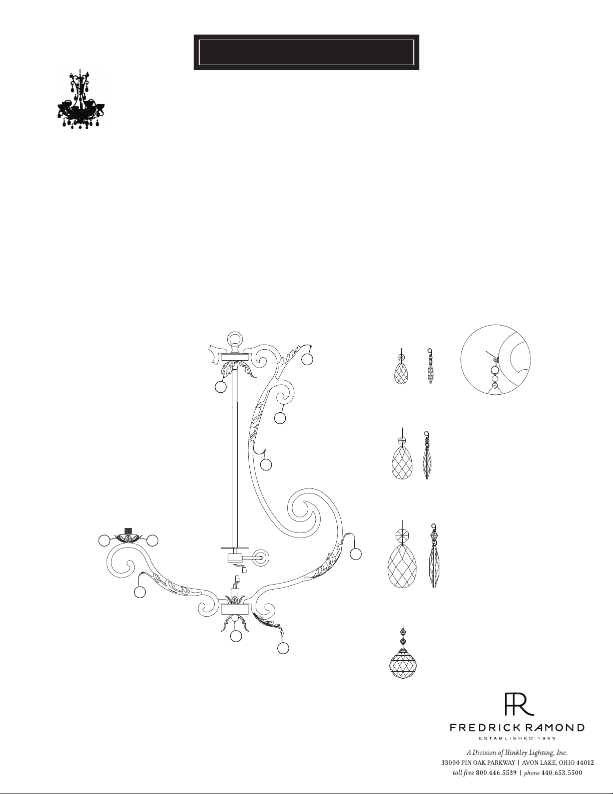
CRYSTAL INSTALLATION INSTRUCTIONS
This Barcelona chandelier use 4 sizes of crystals pendalogues.
STEP 1
1 Starting at the top of the fixture and working your way down, attach , medium pear shaped crystal (2) to eyelet (b).
2 Attach small pear shape crystal (1) to eyelet (a).
3 Attach large pear shaped crystal (3) to eyelet (c).
4 Attach large crystal ball (4) to eyelet (d).
5 Repeat steps 1-4 for remaining arms.
crystal 1
eyelet
b
b
crystal 2
c
c
crystal 2
crystal 3
a
a
c
c
crystal 4
d
b
09.12.08
Page 3

FRIS19-50R
HANGING INSTRUCTIONS FOR FIXTURES THAT WEIGHT MORE THAN 50LBS
SAFETY WAR NING: Read wiring and grounding instructions [FRIS 18]
and any additional directions. Turn power supply off during installation. If new wiring
is required, consult a qualified electrician or local authorities for code requirements.
S T EP 1
1 Shut off electrical current before starting. If the fixture you are replacing is
turned on and off by a wall switch, simply turn the switch off. If not, remove the
appropriate fuse (or open the circut breakers) until the fixture is dead.
• DO NOT restore current - either by fuse, breaker or switch - until the new
fixture is completely wired and in place.
2 Supply wires shall enter the outlet box (a) through any knockout EXCEPT the top
center knockout - See Drawing 1.
S T EP 2
1 Fixture is to be mounted by a 3/8 steel pipe with 3/8 -18 NPSM thread, 3/4”
threads at both ends (not supplied). Pipe should be anchored to structure or
bridging member with sufficient strength to support 4 times the fixtures
weight - see Drawing 2.
2 Adjust pipe so 1/2” of 3/8 steel pipe extends into the junction box, at the center
knock out.
3 Please refer to the back of this sheet to the safety cable installation instructions
and ONLY complete steps 1 and 2 at this time.
[DRAW ING 1]
3/8 steel pipe
a
b
ground
wire
wire
top center
knockout
c
f
d
e
h
j
k
l
m
safety
cable
ST EP 3
1 Thread pipe coupler (b) onto protruding pipe inside outlet box. Secure in place
by tightening allen head screw (c) - see Drawing 1 .
2 Thread hexnut (d) onto threaded nipple (e). Thread nipple (e) into coupler (b).
Secure in place by tightening hexnut (d) against coupler (b) and then tightening
allen screw (f) .
3
thread hexnut (j) onto nipple (e)
4
Thread screw collar loop (k)
. DO NOT tighten hexnut (h) at this time.
onto end of nipple (e)
Adjust screw collar loop height so the half of the exterior thread on
screw collar loop (k)
5
After screw collar loop (k) is adjusted properly , tighten hex nut (j) against
is exposed when canopy (l) is held up to the ceiling.
screw collar loop (k) to secure loop.
S T EP 4
1 Determine length of chain you will require. Attach one end of length of chain to
fixture.
2 Slip threaded ring (m) and canopy (l) onto chain - see Drawing 1.
3 Attach fixture with chain to screw collar loop (k). Please get assistance, weight
and size of fixture is difficult to manage alone.
4 Weave ground wire, supply wire, and safety cable through chain, up through center
of screw collar loop (k), through center of nipple (e) , and out the opening on the
side of coupler (b).
ceiling
joist
[DRAW ING 2]
supply wire
bridge
support
block
junction
box
3/8 steel pipe
hex nut
ceiling
joist
8 00 .42 1. 35 17 W WW. FR ED RI CK RA MO ND. CO M
5.28.08
Page 4

FRIS18
WIRING AND GROUNDING INSTRUCTIONS
SAFETY WARNING: Read wiring and grounding instructions
[FRIS 18] and any additional directions. Turn power supply off during installation. If new
wiring is required, consult a qualified electrician or local authorities for code requirements.
STEP 1 WIRING INSTRUCTIONS
Indoor Fixtures
1 Connect positive supply wire (a) (typically black or the smooth, unmarked side of
the two-conductor cord) to positive fixture lead (b) with appropriately sized twist
on connector - See Drawings 1 or 2.
2 Connect negative supply wire (c) (typically white or the ribbed, marked side of
the two-conductor cord) to negative fixture lead (d).
3 Please refer to the grounding instructions below to complete all electrical
connections.
Outdoor Fixtures
1 Connect positive supply wire (a) (typically black or the smooth unmarked side of
the two-conductor cord) to positive fixture lead (b) with appropriately sized twist
on connector - See Drawings 2 or 3.
2 Connect negative supply wire (c) (typically white or the ribbed, marked side of
the two-conductor cord) to negative fixture lead (d).
3 Cover open end of connectors with silicone sealant to form a watertight seal.
• If installing a wall mount fixture, use caulk to seal gaps between the fixture
mounting plate (backplate) and the wall. This will help prevent water from
entering the outlet box. If the wall surface is lap siding, use caulk and a fixture
mounting platform specially.
4 Please refer to the grounding instructions below to complete all electrical
connections.
STEP 2 GROUNDING INSTRUCTIONS
Flush Mount Fixtures
For positive grounding in a 3-wire electrical system, fasten the fixture ground
wire (e) (typically copper or green plastic coated) to the fixture mounting strap
(1) with the ground screw (2) - See Drawing 1.
Note: On straps for screw supported fixtures, first install the two mounting
screws in strap.
Any remaining tapped hole may be used for the ground screw.
Chain Hung Fixtures
Loop fixture ground wire (e) (typically copper or green plastic coated) under the
head of the ground screw (2) on fixture mounting strap (1) and connect to the
loose end of the fixture ground wire directly to the ground wire of the building
system with appropriately sized twist-on connectors - See Drawing 2.
Post-Mount Fixtures
Connect fixture ground wire (e) (typically copper or green plastic coated) to
power supply ground with appropriately sized twist-on connector inside post.
Cover open end of connector with silicone sealant to form a watertight seal - See
Drawing 3.
supply wire
a c e
b
xture leads
supply wire
a c
b d
xture leads
supply wire
a c
d
b
xture leads
[drawing 1]
twist-on
d
connectors
[drawing 2]
twist-on
e
connectors
1
2
e
[drawing 3]
e
twist-on
connectors
e
1
2
1.30.08
 Loading...