

Page 1
HELIOS
Replacement Parts:
FR43913 / 43914 SLF
GL ASS :
FITURE NO. FR43913SLF - R43913GL
FITURE NO. FR43914SLF - R43912GL
A S S EMBLY INSTRU C T I ONS
The construction of this fixture will be accomplished by first assembling the main body
of the fixture, making all necessary electrical connections, hanging the fixture from the
ceiling and then installing the fixture shade.
SAFETY WARNING: Read wiring and grounding instructions [FRIS 18]
and any additional directions. Turn power supply off during installation. If new wiring
is required, consult a qualified electrician or local authorities for code requirements.
ST E P 1
Note: It will be necessary to determine the length of rods you will require to hang your
fixture at the desired height. After this has been established, please follow the
instructions below.
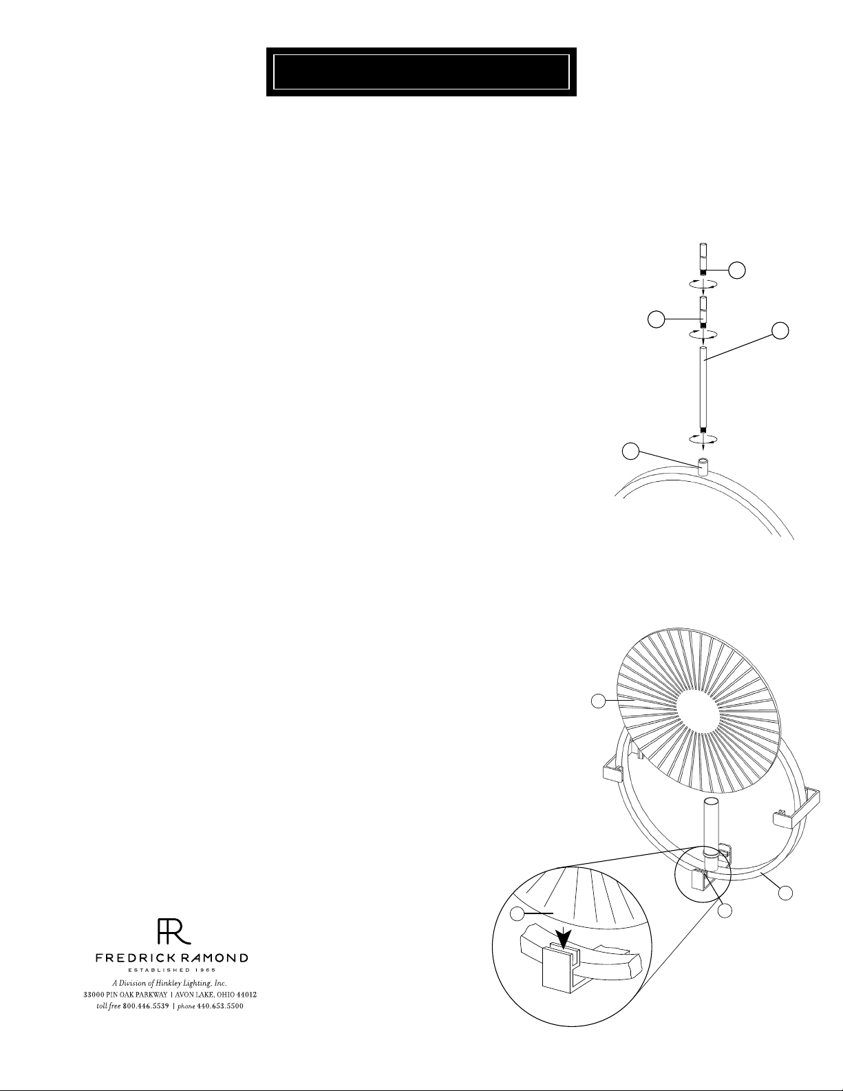
1 Assemble the rods (R) by slipping them into the wire. Thread the first rod into
the coupler (C) located at the top of the fixture - See Drawing 1.
note: It is recommended that a 12” rod (R) be added first.
2 Continue adding rods (R) until desired length has been reached.
[DRAWING 1]
R
C
R
R
S T EP 2
back to this sheet to continue fixture installation.
Refer to Hanging Instruction Sheet [FRIS19-91] to hang fixture.Then refer
S T E P 3
Note: Fixture should be lamped accordingly at this point before proceeding.
1 To install glass (1), slip glass between support clips (2) located on the glass cradle
(3).
Install second piece of glass in same manner.2
[DRAWING 2]
1
3
1
2
06.01.13
Page 2
FRIS19-91
SAFE TY WARNING: Read wiring and grounding instructions [FRIS 18]
and any additional directions. Turn power supply off during installation. If new wiring
is required, consult a qualified electrician or local authorities for code requirements.
STEP 1
1
Shut off electrical current before starting. If the fixture you are replacing is
turned on and off by a wall switch, simply turn the switch off. If not, remove
the appropriate fuse (or open the circut breakers) until the fixture is dead.
• DO NOT restore current - either by fuse, breaker or switch - until the new
fixture is completely wired and in place.
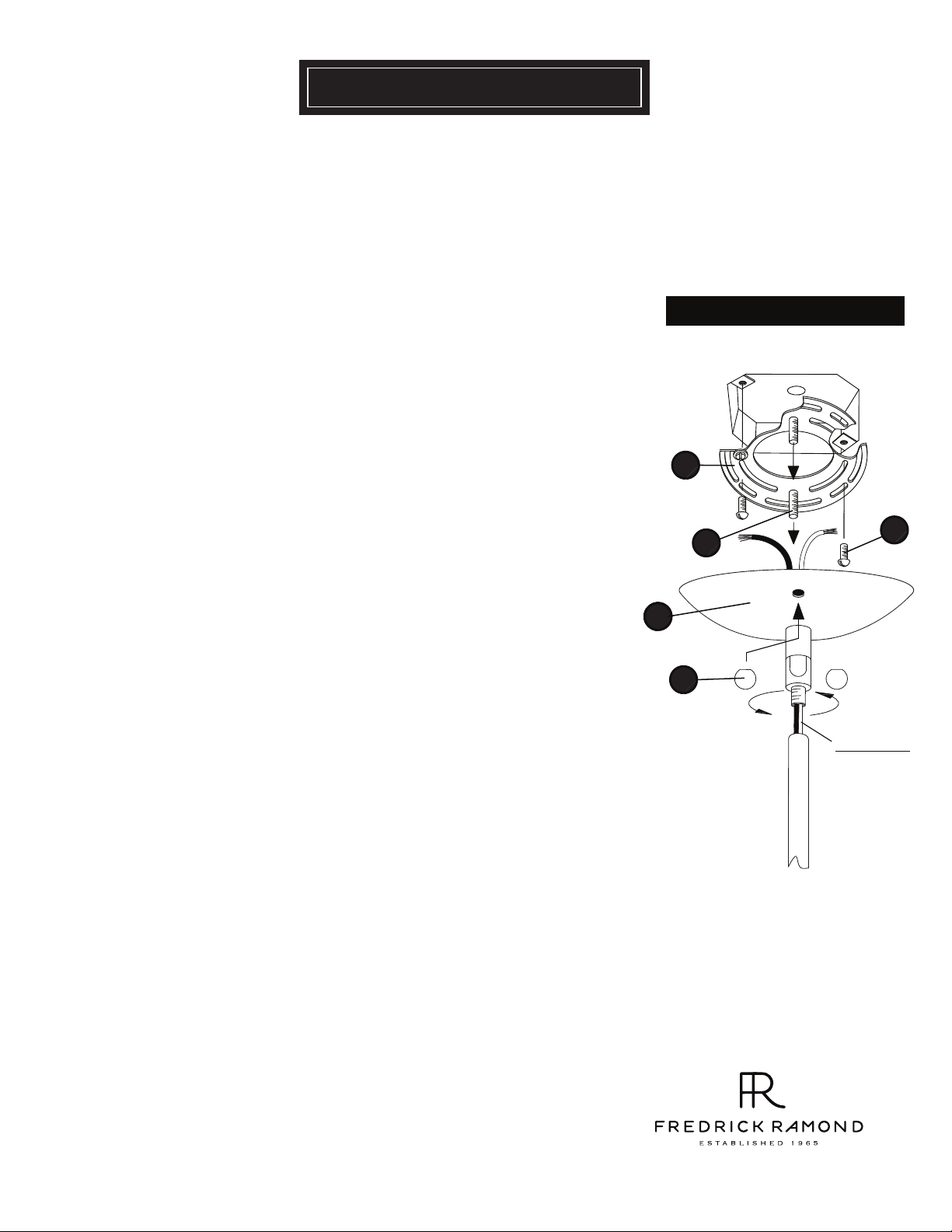
STEP 2
Drawing 1 - Mounting instructions
Slip canopy assembly with swivel (3) along wire and thread onto top of rods
that are attached to fixture.
STEP 3
Thread two long 8-32 (1) screws provided into the mounting strap (2).
Note: the two screws should be threaded into holes that line up with the holes
in the canopy
Attach mount strap (2) to junction box with two short 8-32 screws (5) .
Make wire connections following the instructions on (I.S.18) instruction sheet
provided.
Slip canopy/fixture over screws (1) and secure fixture with ball knobs (4).
(3) - see Drawing 1.
2
5
1
2223
4
supply wire
800. 421.35 17 WWW .F RE DR ICKRAM OND .COM
01.01.12
 Loading...