

Page 1
Bulb s: 60 W CAND.
HELIOS
FR43910 / 43912
A S S EM BLY IN S T RUCTIO N S
Assembly of this fixture will be accomplished by first attaching the mounting hardware
to the junction box, making all necessary wiring connections, mounting the fixture to
the wall and then installing the fixture glass.
SAFETY WAR NI NG: Read wiring and grounding instructions [FRIS 18]
and any additional directions. Turn off power supply during installation . If new wiring
is required, consult a qualified electrician or local authorities for code requirements.
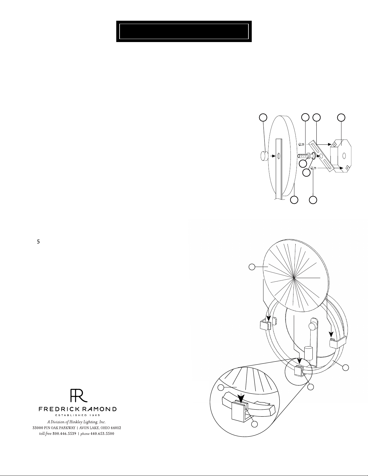
S TEP 1
1 Prepare mounting strap (A) by threading threaded tube (C) into the center hole
of the mounting strap (A), approximately 1/4” - see Drawing 1 .
2 Attach mounting strap (A) to junction box (J) using two short screws (C) provided.
3 Slip lock washer (F1) over nipple (C) and thread hex nut (F) onto threaded tube (C).
4 Hex nut (F) can be tightened against mounting strap (A) after adjusting threaded
tube (C) to proper mounting length.
To mount fixture to wall slip center hole of backplate (E) over threaded tube (C) and
hold the fixture in position.
6 Thread decorative knob (D) onto end of threaded tube (C) and tighten to secure fixture.
[DRAW ING 1]
C
D
A
J
F
F1
E
[DRAWING 2]
1
B
STEP 2
Note: Fixture should be lamped accordingly at this point before proceeding.
1 To install glass (1), slip glass between support clips (2) located on the glass cradle
(3).
06.01.13
3
1
2
2
Page 2
FRIS18
WIRING AND GROUNDING INSTRUCTIONS
SAFETY WARNING: Read wiring and grounding instructions
[FRIS 18] and any additional directions. Turn power supply off during installation. If new
wiring is required, consult a qualified electrician or local authorities for code requirements.
STEP 1 WIRING INSTRUCTIONS
Indoor Fixtures
1 Connect positive supply wire (a) (typically black or the smooth, unmarked side of
the two-conductor cord) to positive fixture lead (b) with appropriately sized twist
on connector - See Drawings 1 or 2.
2 Connect negative supply wire (c) (typically white or the ribbed, marked side of
the two-conductor cord) to negative fixture lead (d).
3 Please refer to the grounding instructions below to complete all electrical
connections.
Outdoor Fixtures
1 Connect positive supply wire (a) (typically black or the smooth unmarked side of
the two-conductor cord) to positive fixture lead (b) with appropriately sized twist
on connector - See Drawings 2 or 3.
2 Connect negative supply wire (c) (typically white or the ribbed, marked side of
the two-conductor cord) to negative fixture lead (d).
3 Cover open end of connectors with silicone sealant to form a watertight seal.
• If installing a wall mount fixture, use caulk to seal gaps between the fixture
mounting plate (backplate) and the wall. This will help prevent water from
entering the outlet box. If the wall surface is lap siding, use caulk and a fixture
mounting platform specially.
4 Please refer to the grounding instructions below to complete all electrical
connections.
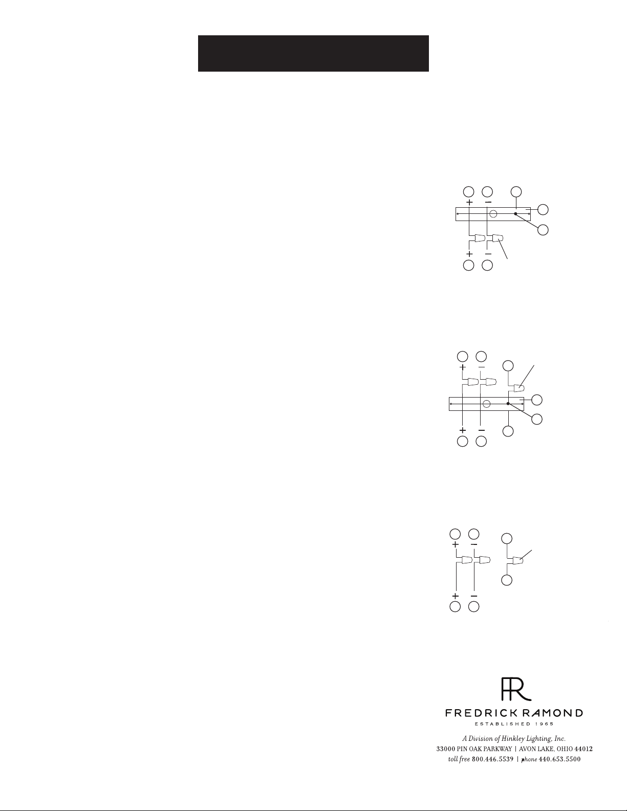
STEP 2 GROUNDING INSTRUCTIONS
Flush Mount Fixtures
For positive grounding in a 3-wire electrical system, fasten the fixture ground
wire (e) (typically copper or green plastic coated) to the fixture mounting strap
(1) with the ground screw (2) - See Drawing 1.
Note: On straps for screw supported fixtures, first install the two mounting
screws in strap.
Any remaining tapped hole may be used for the ground screw.
Chain Hung Fixtures
Loop fixture ground wire (e) (typically copper or green plastic coated) under the
head of the ground screw (2) on fixture mounting strap (1) and connect to the
loose end of the fixture ground wire directly to the ground wire of the building
system with appropriately sized twist-on connectors - See Drawing 2.
Post-Mount Fixtures
Connect fixture ground wire (e) (typically copper or green plastic coated) to
power supply ground with appropriately sized twist-on connector inside post.
Cover open end of connector with silicone sealant to form a watertight seal - See
Drawing 3.
supply wire
a c e
b
xture leads
supply wire
a c
b d
xture leads
supply wire
a c
d
b
xture leads
[drawing 1]
twist-on
d
connectors
[drawing 2]
twist-on
e
connectors
1
2
e
[drawing 3]
e
twist-on
connectors
e
1
2
1.30.08
 Loading...