

Page 1
BIJOU
FR43535 /43536 / 43538
Bulbs: 60W CAN D.
ASSEMBLY INSTRU C T I ONS
Assembly of this fixture will be accomplished by first assembling the main body of the
fixture, attaching mounting hardware to the junction box, making all neccesary electrical
connections,
and then hanging the fixture from the ceiling.
SAFETY WARNING: Read wiring and grounding instructions [FRIS 18]
and any additional directions. Turn power supply off during installation. If new wiring is
required, consult a qualified electrician or local authorities for code requirements.
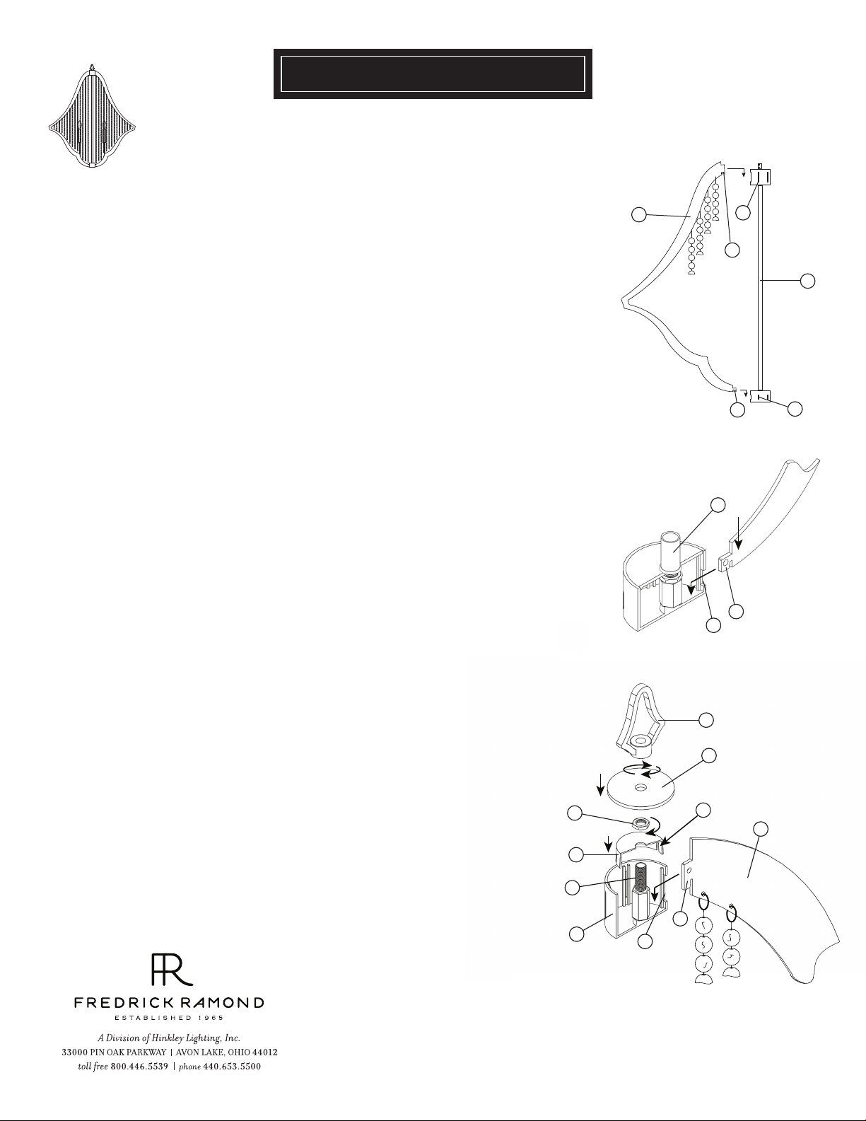
STEP 1
1. It is first necessary to asembly the main body of the fixture, this is acomplished by
taking the arm assemblies (a) and attaching them to the center column assembly
(b) - see Drawing 1. This is accomplished by first inserting lower arm tab (lt) into
lower slot of center column assembly (ls) - see Drawing 1 and 2, and installing the
upper arm tab (ut) into upper body slot (us) of center column assembly (b) - see
Drawing 1 and 3. Repeat process for until all arm assemblies are installed.
2. Next it is necessary to lock the arm assemblies (a) in position. This is accomplished
by slipping locking cap (1) along wire and onto center stem (2) at top of center
column and making sure the slots (s) in the locking cap (1) slide over upper arm tabs (ut)
- see Drawing 3.
3. Thread hex nut (3) onto center stem (2) and tighten down onto locking cap (1) to
secure arms (a) onto center column assembly (b).
a
[DRAWING 2]
[DRAWING 3]
[DRAWING 1]
us
ut
lt
b
lt
ls
b
ls
4. Slip upper body cap (4) along wire and into upper body. Next slip loop (5) along
wire and thread onto center stem (2) and tighten to complete fixture assembly.
5. Fixture can be installed at this time, please refer to hanging instruction sheet
[FRIS19-50R] provided.
01.01.13
5
4
3
s
a
1
2
ut
b
us
Page 2

FRIS19
HA NGING INSTRUCTIONS
SA FE TY WA RN ING: Read wiring and grounding instructions [FRIS 18]
and any additional directions. Turn power supply off during installation. If new wiring
is required, consult a qualified electrician or local authorities for code requirements.
STEP 1
1 Shut off electrical current before starting. If the fixture you are replacing is
turned on and off by a wall switch, simply turn the switch off. If not, remove the
appropriate fuse (or open the circut breakers) until the fixture is dead.
• DO NOT restore current - either by fuse, breaker or switch - until the new
fixture is completely wired and in place.
STEP 2
1 Fasten mounting strap (1) to outlet box (a) with the original outlet box screws (2)
- See Drawing 1.
2 Thread nipple (3) into mounting strap (1).
hex nut (8) several threads to be used to secure threaded nipple (3) later.
3 Thread loop (4) on to end of nipple (3).
4 Slip canopy (b) over loop (4) and adjust height of loop so half of thread area is
exposed.
5
After nipple (3) is adjusted properly thread hex nut (8) with lockwasher (7) up
against mounting strap (1) and tighten to lock threaded nipple (3) in place.
Slip on lockwasher (7) and thread on
[DRAWING 1]
a
1
6
2
3
b
4
7
8
5
supply wire
chain
STEP 3
1 Taking the chain, determine the length you require to hang the fixture.
2 Attach one end of the chain to the top loop of the fixture - See Drawing 2.
3 Now slip loop collar (5) and canopy (b) onto chain.
4 Attach other end of chain to loop (4). Get assistance for this step since fixture
may be heavy and difficult to hold while attaching the chain.
STEP 4
1 Unwrap supply wire and ground wire and weave them up through the chain.
2 Slip supply wire and ground wire through center of loop (4).
3 Connect ground wire to mounting strap (1) using green ground screw (6).
4 Make electrical connections from supply wire to fixture lead wires. Refer to
instruction sheet [FRIS18] and follow all instructions to make all necessary
wiring connections.
5 Slip canopy up firmly against the ceiling and secure by turning the threaded
collar (5) on loop (4) until tight.
ground
wire
[DRAWING 2]
Half of thread area of loop (4) is to be exposed.
This will allow collar (5) to be threaded on later.
b
4
chain
80 0.42 1.3 517 WWW. FRED RICK RAMON D.COM
1.30.08
Page 3

FR43538 CRYSTAL REPLACEMENT ID
PART NO.S
Page 4

FRIS18
WIRING AND GROUNDING INSTRUCTIONS
SAFETY WARNING: Read wiring and grounding instructions
[FRIS 18] and any additional directions. Turn power supply off during installation. If new
wiring is required, consult a qualified electrician or local authorities for code requirements.
STEP 1 WIRING INSTRUCTIONS
Indoor Fixtures
1 Connect positive supply wire (a) (typically black or the smooth, unmarked side of
the two-conductor cord) to positive fixture lead (b) with appropriately sized twist
on connector - See Drawings 1 or 2.
2 Connect negative supply wire (c) (typically white or the ribbed, marked side of
the two-conductor cord) to negative fixture lead (d).
3 Please refer to the grounding instructions below to complete all electrical
connections.
Outdoor Fixtures
1 Connect positive supply wire (a) (typically black or the smooth unmarked side of
the two-conductor cord) to positive fixture lead (b) with appropriately sized twist
on connector - See Drawings 2 or 3.
2 Connect negative supply wire (c) (typically white or the ribbed, marked side of
the two-conductor cord) to negative fixture lead (d).
3 Cover open end of connectors with silicone sealant to form a watertight seal.
• If installing a wall mount fixture, use caulk to seal gaps between the fixture
mounting plate (backplate) and the wall. This will help prevent water from
entering the outlet box. If the wall surface is lap siding, use caulk and a fixture
mounting platform specially.
4 Please refer to the grounding instructions below to complete all electrical
connections.
STEP 2 GROUNDING INSTRUCTIONS
Flush Mount Fixtures
For positive grounding in a 3-wire electrical system, fasten the fixture ground
wire (e) (typically copper or green plastic coated) to the fixture mounting strap
(1) with the ground screw (2) - See Drawing 1.
Note: On straps for screw supported fixtures, first install the two mounting
screws in strap.
Any remaining tapped hole may be used for the ground screw.
Chain Hung Fixtures
Loop fixture ground wire (e) (typically copper or green plastic coated) under the
head of the ground screw (2) on fixture mounting strap (1) and connect to the
loose end of the fixture ground wire directly to the ground wire of the building
system with appropriately sized twist-on connectors - See Drawing 2.
Post-Mount Fixtures
Connect fixture ground wire (e) (typically copper or green plastic coated) to
power supply ground with appropriately sized twist-on connector inside post.
Cover open end of connector with silicone sealant to form a watertight seal - See
Drawing 3.
supply wire
a c e
b
xture leads
supply wire
a c
b d
xture leads
supply wire
a c
d
b
xture leads
[drawing 1]
twist-on
d
connectors
[drawing 2]
twist-on
e
connectors
1
2
e
[drawing 3]
e
twist-on
connectors
e
1
2
1.30.08
 Loading...