

Page 1
FR42872vbz
s
:
AvA
Bulb
A S SEM BL Y I NST R U C T I O N S
The construction of this fixture will be accomplished by first assembling the main body
of the fixture, making all necessary electrical connections, hanging the fixture from the
ceiling and then installing the fixture shade.
60W CAND.
SA FETY WARNING: Read wiring and grounding instructions [FRIS 18]
and any additional directions. Turn power supply off during installation. If new wiring
is required, consult a qualified electrician or local authorities for code requirements.
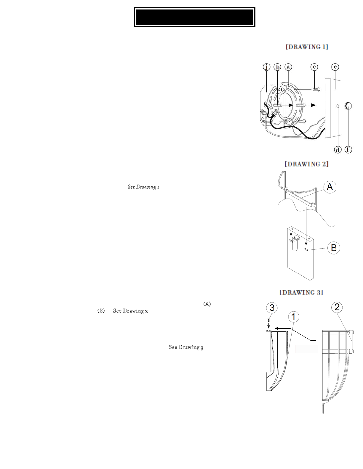
S T E P 1
1 Prepare mounting strap (a) by threading the two long mounting
screws (b) into the back of the mounting strap (a), making sure the
holes into which the screws are threaded match the spacing of holes
(d) in the back plate (e) -- S
2 Attach mounting strap (a) to junction box (j) using two screws (c).
3 Make electrical connections from supply wire to fixture lead wires.
Refer to instruction sheet [FRIS18] and follow all instructions to
make all necessary wiring connections. Then refer back to this sheet
to continue installation of this fixture.
4 To mount fixture, slip the two mounting screws (b) through the two
mounting holes (d) in the back plate (e).
5 While holding fixture in place, thread the two ball knobs (f) on to the
end of the mounting screws (b), and tighten.
ee Drawing 1.
STEP 2
In order to install the shade correctly make sure the notches are in the
upright position. To install the shade slide shade cross bar (
shade notch (
B). -- See Drawing 2
A) into
STEP 3
Slide the cage into overtop of the shade and fixture body and thread the
screw into place in order to lock the cage in place. – S
ee Drawing 3
Page 2
FRIS18
WIRING AND GROUNDING INSTRUCTIONS
SAFETY WARNING: Read wiring and grounding instructions
[FRIS 18] and any additional directions. Turn power supply off during installation. If new
wiring is required, consult a qualified electrician or local authorities for code requirements.
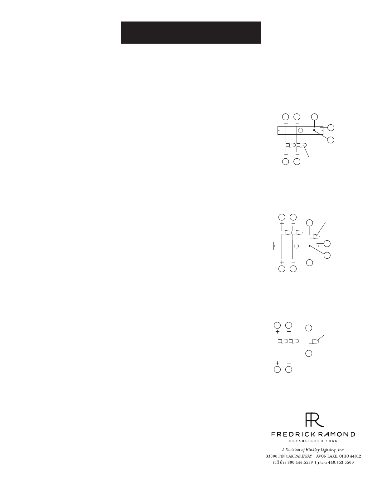
STEP 1 WIRING INSTRUCTIONS
Indoor Fixtures
1 Connect positive supply wire (a) (typically black or the smooth, unmarked side of
the two-conductor cord) to positive fixture lead (b) with appropriately sized twist
on connector - See Drawings 1 or 2.
2 Connect negative supply wire (c) (typically white or the ribbed, marked side of
the two-conductor cord) to negative fixture lead (d).
3 Please refer to the grounding instructions below to complete all electrical
connections.
Outdoor Fixtures
1 Connect positive supply wire (a) (typically black or the smooth unmarked side of
the two-conductor cord) to positive fixture lead (b) with appropriately sized twist
on connector - See Drawings 2 or 3.
2 Connect negative supply wire (c) (typically white or the ribbed, marked side of
the two-conductor cord) to negative fixture lead (d).
3 Cover open end of connectors with silicone sealant to form a watertight seal.
• If installing a wall mount fixture, use caulk to seal gaps between the fixture
mounting plate (backplate) and the wall. This will help prevent water from
entering the outlet box. If the wall surface is lap siding, use caulk and a fixture
mounting platform specially.
4 Please refer to the grounding instructions below to complete all electrical
connections.
STEP 2 GROUNDING INSTRUCTIONS
Flush Mount Fixtures
For positive grounding in a 3-wire electrical system, fasten the fixture ground
wire (e) (typically copper or green plastic coated) to the fixture mounting strap
(1) with the ground screw (2) - See Drawing 1.
Note: On straps for screw supported fixtures, first install the two mounting
screws in strap.
Any remaining tapped hole may be used for the ground screw.
Chain Hung Fixtures
Loop fixture ground wire (e) (typically copper or green plastic coated) under the
head of the ground screw (2) on fixture mounting strap (1) and connect to the
loose end of the fixture ground wire directly to the ground wire of the building
system with appropriately sized twist-on connectors - See Drawing 2.
Post-Mount Fixtures
Connect fixture ground wire (e) (typically copper or green plastic coated) to
power supply ground with appropriately sized twist-on connector inside post.
Cover open end of connector with silicone sealant to form a watertight seal - See
Drawing 3.
supply wire
a c e
b
xture leads
supply wire
a c
b d
xture leads
supply wire
a c
d
b
xture leads
[drawing 1]
twist-on
d
connectors
[drawing 2]
twist-on
e
connectors
1
2
e
[drawing 3]
e
twist-on
connectors
e
1
2
1.30.08
 Loading...