

Page 1
fR,41943,441946,41948,41949,41950
Bulbs: 60W CAND.
KARMA
ASSEMBLY INSTRU C T IONS
Assembly of this fixture will be accomplished by first determining the length of stem
required, attaching the mounting strap to the junction box, making all necessary
electrical connections, and hanging the fixture from the ceiling.
SAFETY WARNING: Read wiring and grounding instructions [FRIS 18]
and any additional directions. Turn power supply off during installation. If new wiring
is required, consult a qualified electrician or local authorities for code requirements.
ST E P 1
1 Determine the overall length you will need the assembled fixture to be.
2 Determine what stems will be needed to achieve the overall length you
require.(Additional stems are available and can be ordered. Ask your local
Fredrick Ramond representative or visit www.fredrickramond.com for
information.
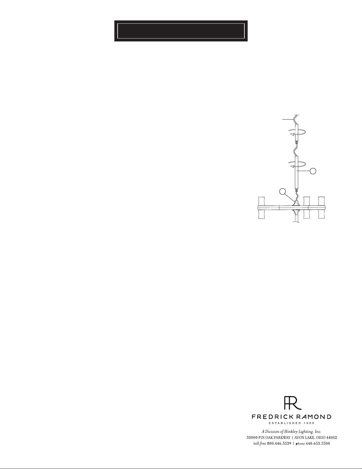
3 Install first stem (a) by slipping it along the supply wire of the fixture, and
threading it into decorative coupler (b) of the main body.
4
Continue adding stems (a) until determined length is acheived.
5
Fixture is ready for installation. Follow instruction sheet [FRIS19-70T] provided.
[DRAWI NG 1]
supply
wire
a
b
After installation fixture can be lamped accordingly.
6
01.01.13
Page 2
FRIS19-70T
[DRAWING 1]
SAFETY WARNING: Read wiring and grounding instructions [FRIS 18]
and any additional directions. Turn power supply off during installation. If new wiring
is required, consult a qualified electrician or local authorities for code requirements.
STEP 1
1 Shut off electrical current before starting. If the fixture you are replacing is
turned on and off by a wall switch, simply turn the switch off. If not, remove the
appropriate fuse (or open the circut breakers) until the fixture is dead.
• DO NOT restore current - either by fuse, breaker or switch - until the new
fixture is completely wired and in place.
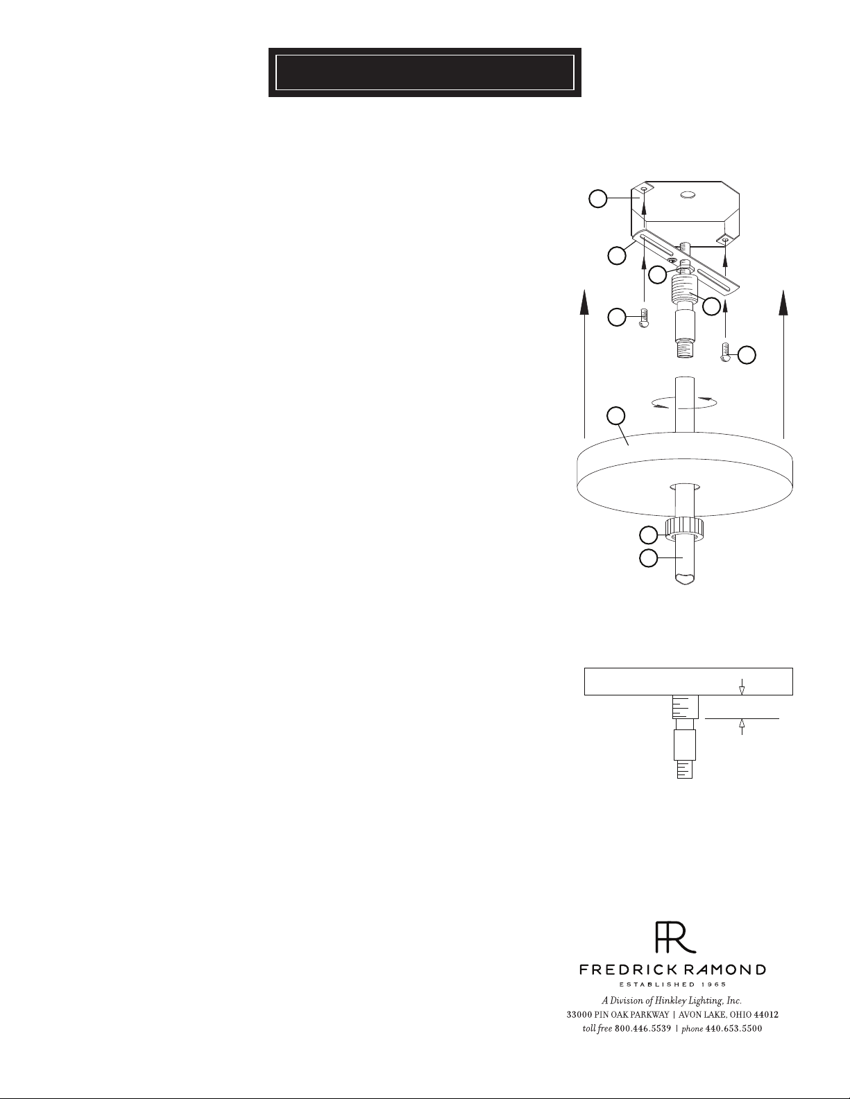
STEP 2
1 Take swivel (g) and thread tube with hex nut into mounting strap (e)
approximately 1/2” -see Drawing 1.
2 Temporarily install mounting strap (e) with swivel (g) onto junction box.
slip canopy (d) over swivel and up to ceiling and adjust swivel height, when
adjusted correctly tighten hex nut (h) against mounting strap (e) to lock in
position. Remove strap and swivel from junction box - see Drawing 1 & 2 .
3 Slip, in this order swivel collar (c) and canopy (d) over stems (b),
Now slip mounting strap (e) with swivel (g) along supply wire and thread swivel
into top of stem (b).
4 With assistance, lift fixture with stems (b) and crossbar with swivel (e) previously
attached and mount to the junction box (j) with two screws (f).
j
e
h
g
f
f
d
c
b
STEP 3
1 Make electrical connections from supply wire to fixture lead wires. Refer to
instruction sheet (I.S. 18) and follow all instructions to make all neccessary
wiring connections.
2 Slip canopy (d) up along rods (b) and cover mounting crossbar with swivel (e).
3 Slip retaining ring (c) up to canopy and thread onto coupler (g), located on the
mounting crossbar with swivel (e), to secure canopy.
[DRAWING 2]
1/2” of thread
showing
01.01.13
Page 3

FRIS18
WIRING AND GROUNDING INSTRUCTIONS
SAFETY WARNING: Read wiring and grounding instructions
[FRIS 18] and any additional directions. Turn power supply off during installation. If new
wiring is required, consult a qualified electrician or local authorities for code requirements.
STEP 1 WIRING INSTRUCTIONS
Indoor Fixtures
1 Connect positive supply wire (a) (typically black or the smooth, unmarked side of
the two-conductor cord) to positive fixture lead (b) with appropriately sized twist
on connector - See Drawings 1 or 2.
2 Connect negative supply wire (c) (typically white or the ribbed, marked side of
the two-conductor cord) to negative fixture lead (d).
3 Please refer to the grounding instructions below to complete all electrical
connections.
Outdoor Fixtures
1 Connect positive supply wire (a) (typically black or the smooth unmarked side of
the two-conductor cord) to positive fixture lead (b) with appropriately sized twist
on connector - See Drawings 2 or 3.
2 Connect negative supply wire (c) (typically white or the ribbed, marked side of
the two-conductor cord) to negative fixture lead (d).
3 Cover open end of connectors with silicone sealant to form a watertight seal.
• If installing a wall mount fixture, use caulk to seal gaps between the fixture
mounting plate (backplate) and the wall. This will help prevent water from
entering the outlet box. If the wall surface is lap siding, use caulk and a fixture
mounting platform specially.
4 Please refer to the grounding instructions below to complete all electrical
connections.
STEP 2 GROUNDING INSTRUCTIONS
Flush Mount Fixtures
For positive grounding in a 3-wire electrical system, fasten the fixture ground
wire (e) (typically copper or green plastic coated) to the fixture mounting strap
(1) with the ground screw (2) - See Drawing 1.
Note: On straps for screw supported fixtures, first install the two mounting
screws in strap.
Any remaining tapped hole may be used for the ground screw.
Chain Hung Fixtures
Loop fixture ground wire (e) (typically copper or green plastic coated) under the
head of the ground screw (2) on fixture mounting strap (1) and connect to the
loose end of the fixture ground wire directly to the ground wire of the building
system with appropriately sized twist-on connectors - See Drawing 2.
Post-Mount Fixtures
Connect fixture ground wire (e) (typically copper or green plastic coated) to
power supply ground with appropriately sized twist-on connector inside post.
Cover open end of connector with silicone sealant to form a watertight seal - See
Drawing 3.
supply wire
a c e
b
xture leads
supply wire
a c
b d
xture leads
supply wire
a c
d
b
xture leads
[drawing 1]
twist-on
d
connectors
[drawing 2]
twist-on
e
connectors
1
2
e
[drawing 3]
e
twist-on
connectors
e
1
2
1.30.08
 Loading...