

Page 1
BROADWAY
fR41433, fR41434 fR41435pal
Bulbs: 60W g-9. Replacement Parts: GLASS: R 41430GL
ASSEMBLY INSTRU CTION S
Assembly of this fixture will be accomplished by first determining the length of stem
required, attaching the mounting strap to the junction box, making all necessary
electrical connections, hanging the fixture from the ceiling and then installing the
lamps.
SAFETY WARNING: Read wiring and grounding instructions [FRIS 18]
and any additional directions. Turn power supply off during installation. If new wiring
is required, consult a qualified electrician or local authorities for code requirements.
STEP 1
1 Follow mounting instruction sheet FRIS19-30 provided with fixture. After installation
return to this section of the instructions on lamping the fixture.
STEP 2
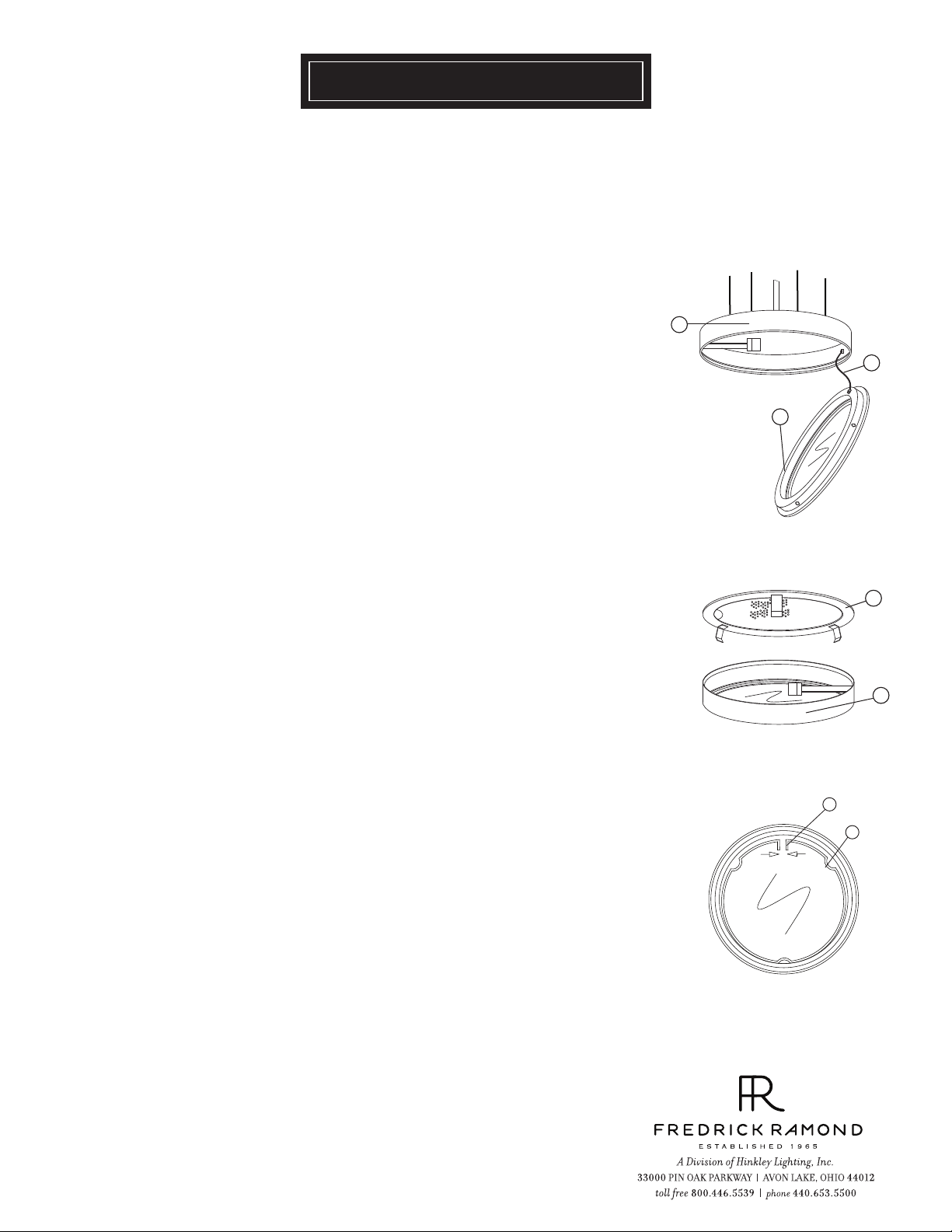
1 To lamp center hub of fixture, remove glass retainer ring (2) frombottom of the
main body (1). NOTE: the glass retainer ring is held in position by spring tension
and can be easily removed by pulling firmly on the edge at the split line. Retainer
ring is attached to the fixture by a wire cable (3) and will not fall when
released - See Drawing 1.
STEP 3
1 To lamp remaing hubs (5) , remove the top protective screen (4) by lifting them off
of the top main body assembly by pulling up on them with the aid of the assistance
hole punch in the edge of the screen. These lids are held in position by spring
tension and can be removed easily. After lamping the protective screen can be
snapped back into place - see Drawing 2.
2
Fixture is complete.
STEP 4
1 Glass is held by a “C” shape spring ring (r). To remove, replace, or install glass
it is necessary to pinch the two short tabs (t) of the ring together, after glass is installed ring
can be replaced in same manner -see Drawing 3.
[DRAWING 1]
1
3
2
[DRAWING 2]
4
5
[DRAWING 3]
t
r
06.01.11
Page 2
FRIS19-30
CA BL E HANGING INSTRUCTIONS
SAFETY WA RN ING: Read wiring and grounding instructions [FRIS 18]
and any additional directions. Turn power supply off during installation. If new wiring
is required, consult a qualified electrician or local authorities for code requirements.
STEP 1
1 Shut off electrical current before starting. If the fixture you are replacing is
turned on and off by a wall switch, simply turn the switch off. If not, remove the
appropriate fuse (or open the circuit breakers) until the fixture is dead.
• DO NOT restore current - either by fuse, breaker or switch - until the new
fixture is completely wired and in place.
STEP 2
1 It will be necessary to determine the length of cable (f) that you will require to hang the fixture
at the proper height. To get an approximate lenght of cable requried, measure
the distance between the floor and the ceiling and subtract the distance the fixture
will be above the floor. The remainder is the approximate lenght of cable required.
2 To aid in hanging, the cables (f) can be measured from the top of the fixture and marked
with a piece of tape at the approximate length required.
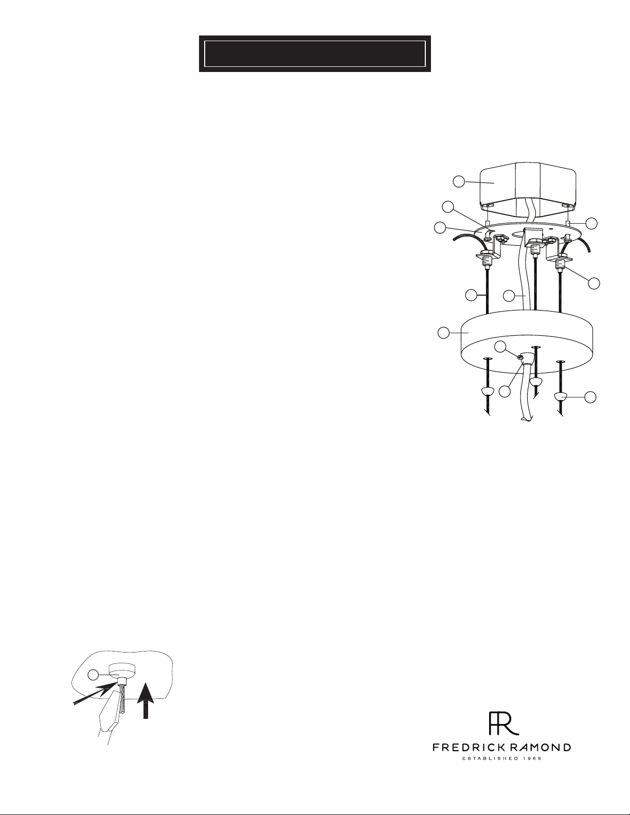
3 To prepare cables for installation, first slide one cover cap (d) onto each cable (f), small end
first. Then feed one cable throught the appropriate holes in the canopy (c) - see Drawing 1.
4 Take mounting assembly (a) and feed one cable (f) through the cable locking mechanism
(e) and pull cable through and up to the previously measured point. NOTE: cable locking
mechanism will lock cable in place when pulled down. To release cable for adjustment
read instructions under Drawing (2).
5 Fixture can now be hung. This is accomplished by first threading 2 screws (b) into appropriate holes
in junction box. Do not tighten at this time.
6 Get assistance during this operation. Lift mounting plate (a) with fixture attached, up to junction box
(j) slip heads of previously installed screws (b) through keyhole slots (k) and twist, till screws
hit end of slot. Then thighten screws (b) to secure mounting plate (a).
7 Take supply wire (i) and feed through wire keeper (g) on canopy and up to junction box.
Allow approcimately 6” of slack in the supply wire (i) so it will hang in a lazy “S” fashion.
Make all necessary electrical connections by following instruction sheet FRIS-18 supplied.
8 Final cable adjustments can be made at this time, to level fixture and adjust height.
9 Slip canopy (c) up along cables (f) and supply wire (i), over mounting assembly (a), and up to
ceiling. Slip cover caps (d) align cables and thread onto cable locking mechanism (e) to
secure canopy to mounting assembly.
10 To secure supply wire location tighen screw (h). NOTE: do not over tighten and damage wire.
[DRAWING 1]
j
k
a
b
e
f i
c
h
g
d
[DRAWING 2]
outside cylinder
screwdriver
Note: If during the adjustment process too much cable is pulled up, the spring loaded
locking mechanism can be released by taking a screw driver and pushing up on the
e
center cylinder of the locking mechanism. This will release the spring pressure and
allow the cable to be pulled back out (use caution to prevent the cable from being damaged).
8 00 .42 1. 35 17 W WW. FR ED RI CK RA MO ND. CO M
06.01.11
Page 3

FRIS18
WIRING AND GROUNDING INSTRUCTIONS
SAFETY WARNING: Read wiring and grounding instructions [FRIS 18]
and any additional directions. Turn power supply off during installation. If new wiring
is required, consult a qualified electrician or local authorities for code requirements.
s te p 1 W I R I N G I N S T R UC T I O N S
Indoor Fixtures
1 Connect positive supply wire (a) (typically black or the smooth, unmarked side of
the two-conductor cord) to positive fixture lead (b) with appropriately sized twist
on connector - See Drawings 1 or 2.
2 Connect negative supply wire (c) (typically white or the ribbed, marked side of
the two-conductor cord) to negative fixture lead (d).
3 Please refer to the grounding instructions below to complete all electrical
connections.
Outdoor Fixtures
1 Connect positive supply wire (a) (typically black or the smooth unmarked side of
the two-conductor cord) to positive fixture lead (b) with appropriately sized twist
on connector - See Drawings 2 or 3.
2 Connect negative supply wire (c) (typically white or the ribbed, marked side of
the two-conductor cord) to negative fixture lead (d).
3 Cover open end of connectors with silicone sealant to form a watertight seal.
• If installing a wall mount fixture, use caulk to seal gaps between the fixture
mounting plate (backplate) and the wall. This will help prevent water from
entering the outlet box. If the wall surface is lap siding, use caulk and a fixture
mounting platform specially.
4 Please refer to the grounding instructions below to complete all electrical
connections.
s t e p 2 g r o u n d i ng i n s t r u c t i on s
Flush Mount Fixtures
For positive grounding in a 3-wire electrical system, fasten the fixture ground
wire (e) (typically copper or green plastic coated) to the fixture mounting strap
(1) with the ground screw (2) - See Drawing 1.
Note: On straps for screw supported fixtures, first install the two mounting
screws in strap.
Any remaining tapped hole may be used for the ground screw.
Chain Hung Fixtures
Loop fixture ground wire (e) (typically copper or green plastic coated) under the
head of the ground screw (2) on fixture mounting strap (1) and connect to the
loose end of the fixture ground wire directly to the ground wire of the building
system with appropriately sized twist-on connectors - See Drawing 2.
Post-Mount Fixtures
Connect fixture ground wire (e) (typically copper or green plastic coated) to
power supply ground with appropriately sized twist-on connector inside post.
Cover open end of connector with silicone sealant to form a watertight seal - See
Drawing 3.
supply wire
a c e
b
fixture leads
supply wire
a c
b d
fixture leads
supply wire
a c
d
b
fixture leads
[drawing 1]
twist-on
d
connectors
[drawing 2]
twist-on
e
connectors
1
2
e
[drawing 3]
e
twist-on
connectors
e
1
2
80 0. 421.3 517 www.frEDrickramon d.com
1.30.08
 Loading...