

Page 1
ION
FR36501 ANG/ANB/ANS
Bulbs: 60W CAND.
A S S EMBLY INSTRU CTION S
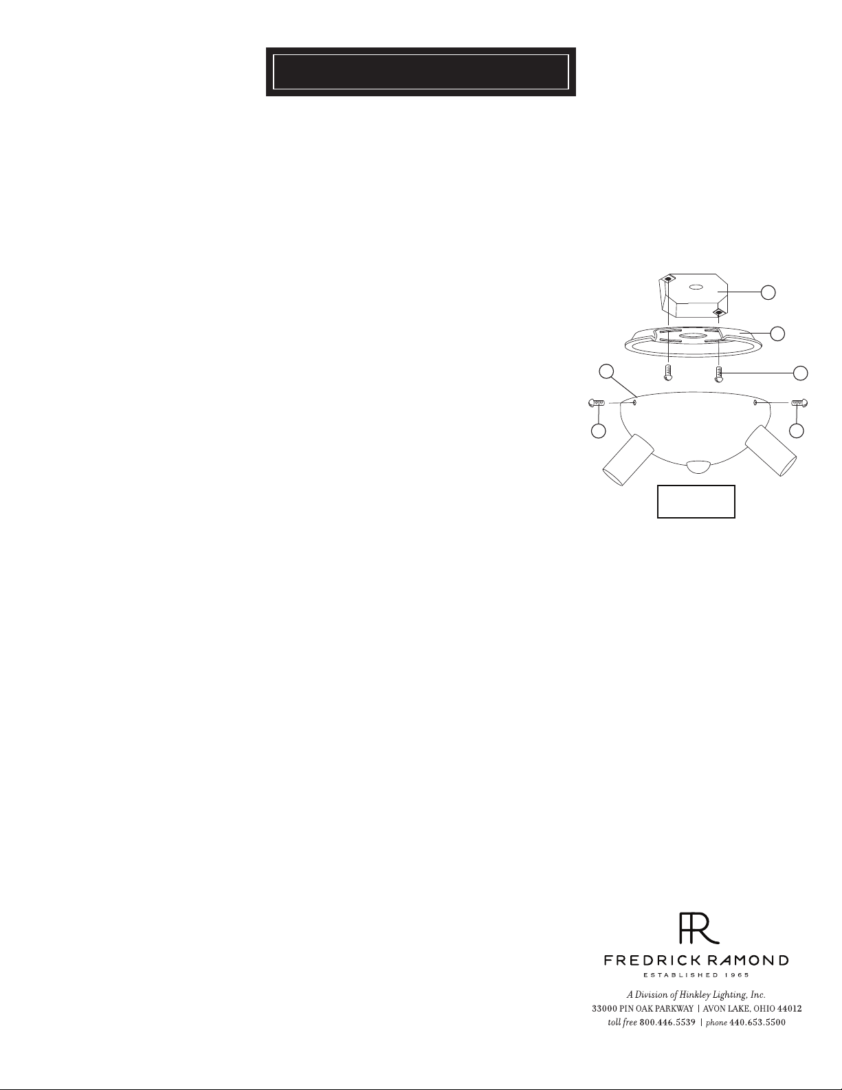
Assembly of this fixture will be accomplished by first determining the length of stem
required, attaching the mounting strap to the junction box, making all necessary
electrical connections, and hanging the fixture from the ceiling or wall.
[DRAWING 1]
SAFETY WARNING: Read wiring and grounding instructions [FRIS 18]
and any additional directions. Turn power supply off during installation. If new wiring
is required, consult a qualified electrician or local authorities for code requirements.
STEP 1
1 Attach mounting plate (a) to junstion box (j) with screws (b) provided
-See Drawing 1
2 Make all wiring connections following instruction sheet (FRIS 18) provided.
Please follow all necesary precautions.
3 After all connections are made, slip canopy (c) over mounting plate (a) and hold
in poistion while tightening screws (d). NOTE: As screws (d) are tighten canopy
will move upward and be flush against the ceiling.
4 Installation is complete and fixture can now be lamped.
5 If mounting to the wall follow same procedures as outlined above.
STEP 2
1 Fixture can be lamped accordingly at this time.
STEP 3
1 Decorative wires on fixture can be teased to create a variaty of shapes and sizes.
j
a
c
d
wires removed
for clarity
b
d
01.01.13
Page 2
FRIS18
WIRING AND GROUNDING INSTRUCTIONS
SAFETY WARNING: Read wiring and grounding instructions [FRIS 18]
and any additional directions. Turn power supply off during installation. If new wiring
is required, consult a qualified electrician or local authorities for code requirements.
s t e p 1 W I R I N G I N S T R U C T IO N S
Indoor Fixtures
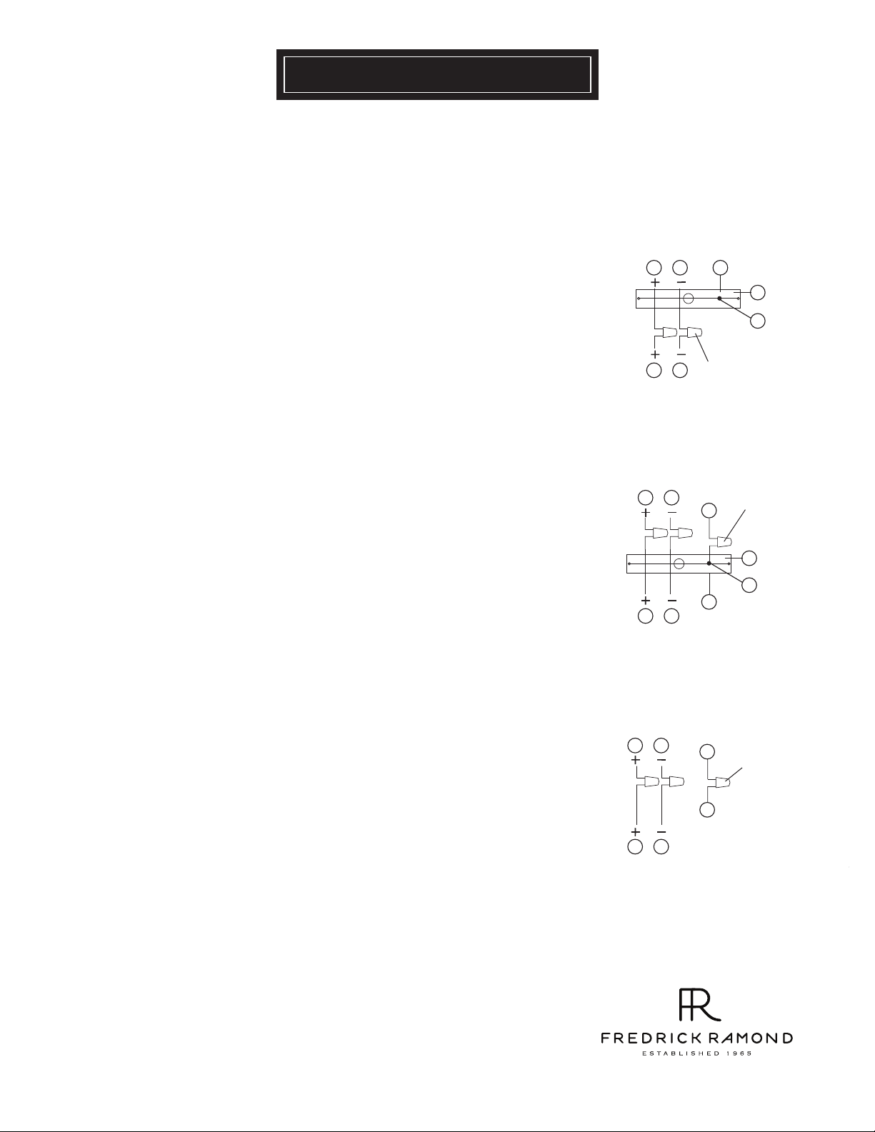
1 Connect positive supply wire (a) (typically black or the smooth, unmarked side of
the two-conductor cord) to positive fixture lead (b) with appropriately sized twist
on connector - See Drawings 1 or 2.
2 Connect negative supply wire (c) (typically white or the ribbed, marked side of
the two-conductor cord) to negative fixture lead (d).
3 Please refer to the grounding instructions below to complete all electrical
connections.
Outdoor Fixtures
1 Connect positive supply wire (a) (typically black or the smooth unmarked side of
the two-conductor cord) to positive fixture lead (b) with appropriately sized twist
on connector - See Drawings 2 or 3.
2 Connect negative supply wire (c) (typically white or the ribbed, marked side of
the two-conductor cord) to negative fixture lead (d).
3 Cover open end of connectors with silicone sealant to form a watertight seal.
• If installing a wall mount fixture, use caulk to seal gaps between the fixture
mounting plate (backplate) and the wall. This will help prevent water from
entering the outlet box. If the wall surface is lap siding, use caulk and a fixture
mounting platform specially.
4 Please refer to the grounding instructions below to complete all electrical
connections.
s t e p 2 g r o un di ng i n s t r uc t i on s
Flush Mount Fixtures
For positive grounding in a 3-wire electrical system, fasten the fixture ground
wire (e) (typically copper or green plastic coated) to the fixture mounting strap
(1) with the ground screw (2) - See Drawing 1.
Note: On straps for screw supported fixtures, first install the two mounting
screws in strap.
Any remaining tapped hole may be used for the ground screw.
Chain Hung Fixtures
Loop fixture ground wire (e) (typically copper or green plastic coated) under the
head of the ground screw (2) on fixture mounting strap (1) and connect to the
loose end of the fixture ground wire directly to the ground wire of the building
system with appropriately sized twist-on connectors - See Drawing 2.
Post-Mount Fixtures
Connect fixture ground wire (e) (typically copper or green plastic coated) to
power supply ground with appropriately sized twist-on connector inside post.
Cover open end of connector with silicone sealant to form a watertight seal - See
Drawing 3.
supply wire
a c e
b
fixture leads
supply wire
a c
b d
fixture leads
supply wire
a c
d
b
fixture leads
[drawing 1]
twist-on
d
connectors
[drawing 2]
twist-on
e
connectors
1
2
e
[drawing 3]
e
twist-on
connectors
e
1
2
80 0. 421.3 517 www.frEDrickramon d.com
1.30.08
 Loading...