

Page 1
Assembly and Installation instructions for 6638BK
Please do the following to insure safe and easy installation:
A. Read installation instructions and review diagrams thoroughly before beginning.
B. For proper installation, secure sevices of a qualified electrician.
DRAWING 1
DISCONNECT THE POWER (CAUTION)
Always shut off power at the circuit breaker or disconnect fuse when installing or
or repairing this item.
1. WIRE POWER TO FIXTURE LOCATION
A. Be sure to consult local codes before beginning electrical work.
B. Wire power through conduit that meets local codes from the power source to
the site of the fixture.
C. It is recommended that there is 100 inches of wire above grade at the end of the run
to allow for wiring of fixture.
2. PREPARE FOOTING
A. To ensure adequate support, the concrete footing used to mount the 6638 pole
should be 16” cubed, or according to local building codes. See installation instruction
sheet for more details.
B. This pole is supplied with a cast metal template for installing the anchor bolts in
there correct position. -See Drawing 2.
C. Thread anchor bolts into the corners of the cast metal triangle template. Making sure
the end of the bolt measure 2” (but not less than 1-3/4” ) from the bottom of the metal
template. -See Drawing 2.
D. Pour cement into prepared hole and before cement sets place prepared template
with anchor bolts into cement. Making sure cast metal template rests on top of cement.
E
F
D
S
H
DRAWING 2
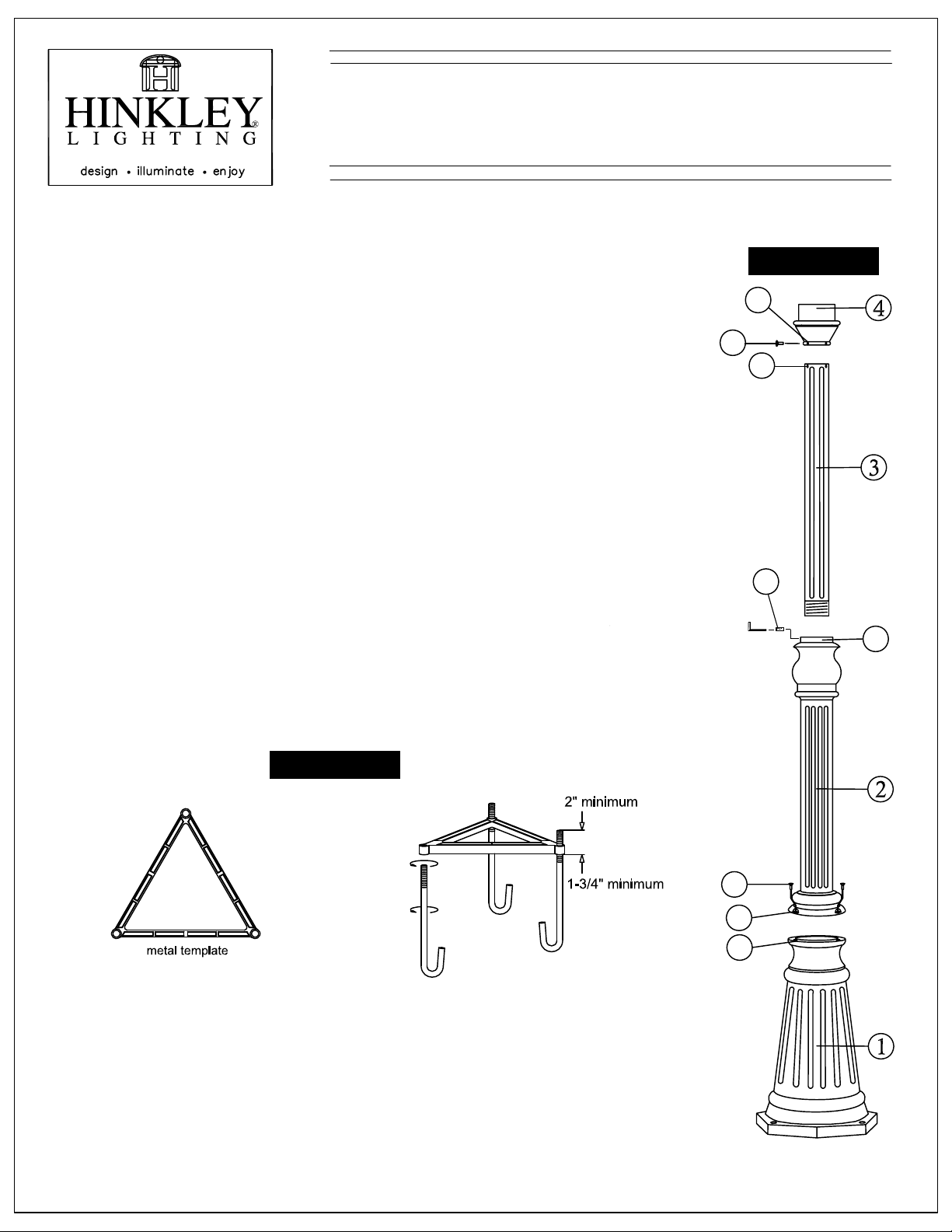
3. POLE ASSEMBLY
1. Take mid section of pole (2) and line up holes (A) with holes (B) in the
bottom section (1) - See Drawing 1 for reference.
2. Thread allen head screws (C) in place, to secure sections (1) and (2).
3. Thread top section (3) into top of mid section (2) and tighten.
4. Thread set screw (S) into threaded hole located in area (H) and tighten to secure top
section of pole.
4. Slip post cap (4) over top of section (3). Making sure holes (D) and (E) are aligned.
5. Thread in flat head phillip screws(F) into hole (E) to secure post cap (4).
6. Pole is complete and may be mounted to footer.
C
A
B
Page 2
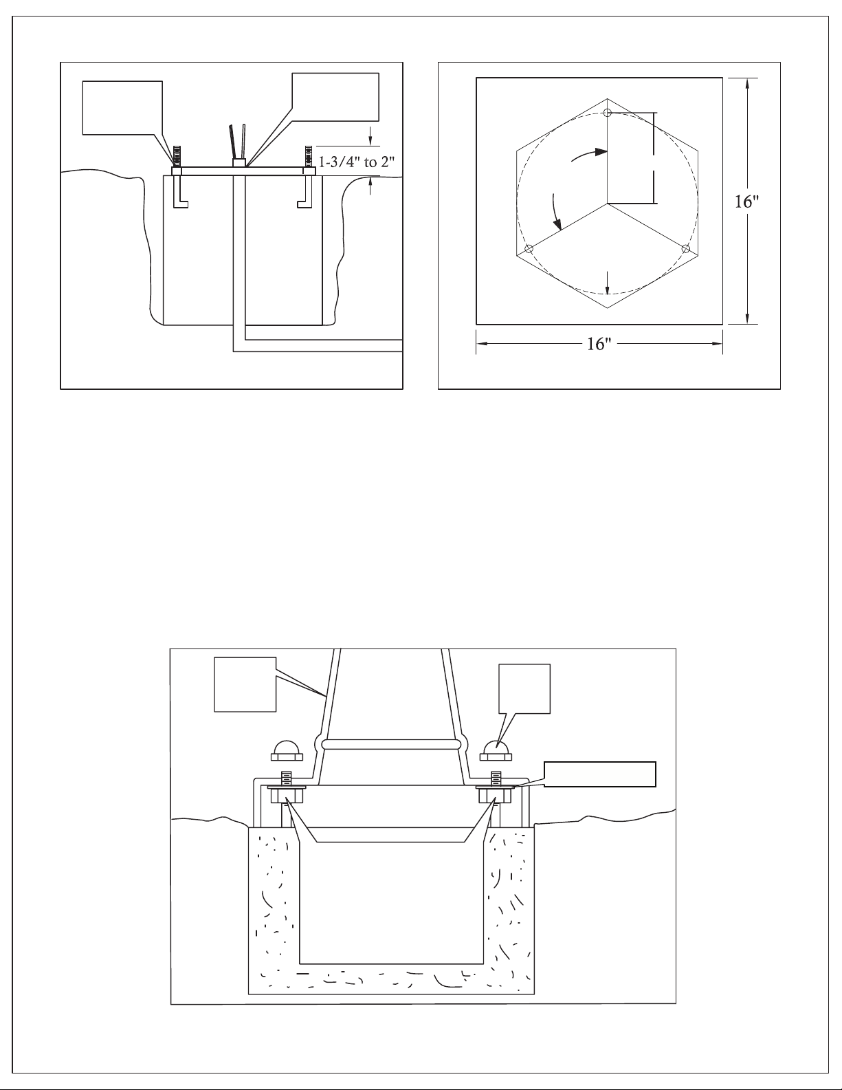
FOOTING DETAIL VIEW
BOLT PATTERN
METAL
TEMPLATE
W/ BOLTS
4. MOUNTING LAMP POST TO FOOTING
ELECTRICAL
SUPPLY
WIRE
120
DEGREES
4-1/2”
9” bolt circle
use metal template provided with polecheck local building codes prior to installation
1. Thread hex nuts onto anchor bolts and adjust to that the tops of the hex nuts are 1-1/4” above the
footing - see Diagram C
2. Slip flat metal washer onto anchor bolts.
3. Slip pole base over anchor bolts and check for plum. If pole is not plum adjustments can be made to
hex nuts under base to correct any leaning.
4. When pole is plum finish installation by threading on the and tightening the cap nuts provided.
Diagram C
POST
BASE
HEX NUTS CAN BE
CAP
NUT
FLAT WASHER
grand
ADJUSTED TO
INSURE
POLE IS PLUM
revised 12-01-10
 Loading...