

Page 1
____Assembly Instructions____
Item No. 5882/5884/5886
Drawing 1 – Fixture Mounting
Drawing 2 – Glass Installation
3
S
start here---
1. Find a clear area in which you can work.
2. Unpack Fixture and glass from carton.
3. Carefully Review Instructions Prior to assembly.
*** The construction of this fixture will be accomplished by first assembling the
main body of the fixture, installing the glass, attaching the mounting strap to
the junction box, making all necessary electrical connections, and mounting the
fixture to the wall.
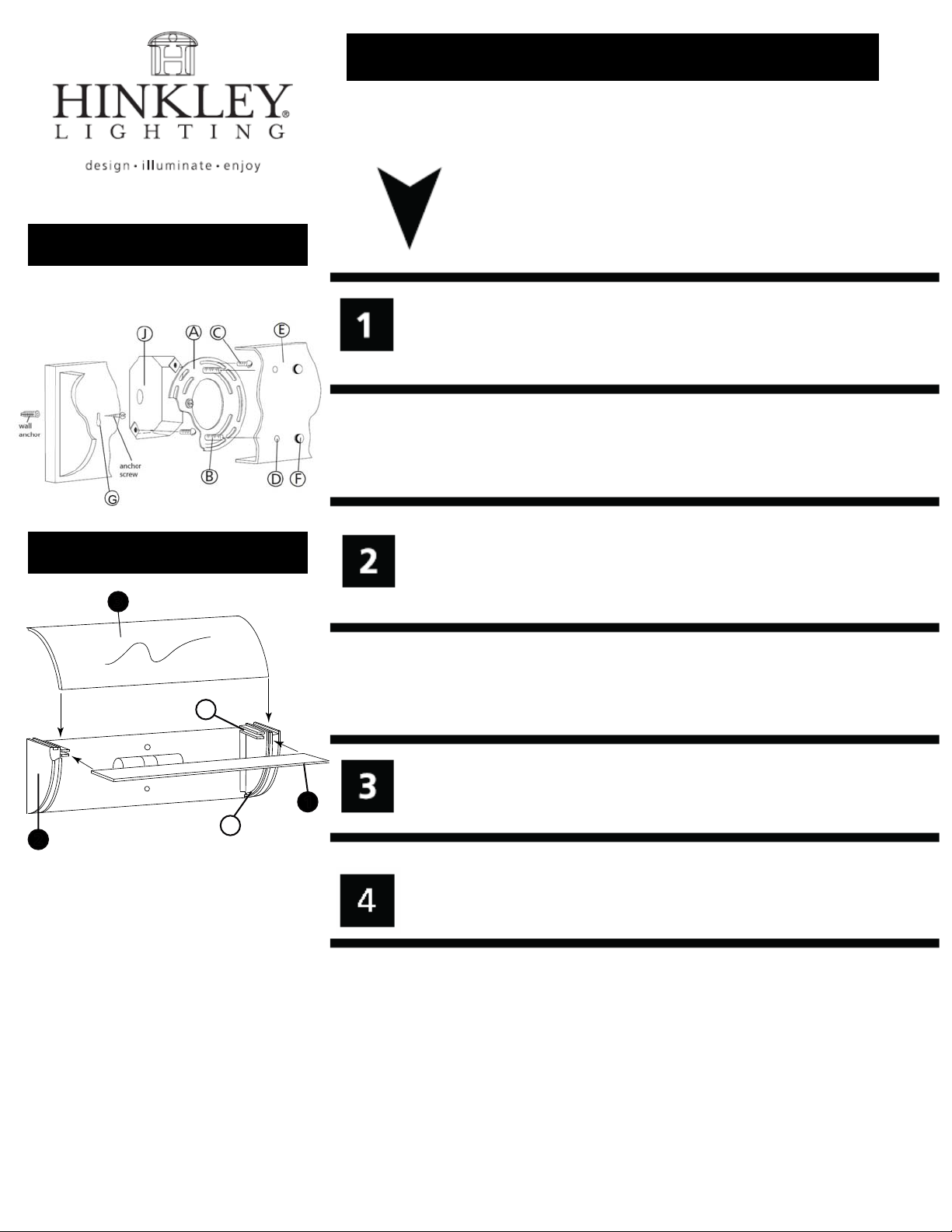
1. Prepare mounting strap (A) by threading the two 1 1/4’’ long mounting screws
(B) into the back of the mounting strap (A) - see Drawing 1.
2. Attach mounting strap (A) to junction box (J) using two 1’’screws(C).
3. Additional wall anchors supplied can be installed at keyhole points (G).
SAFETY WARNING: READ WIRING AND GROUNDING
INSTRUCTIONS (I.S. 18) AND ANY ADDITIONAL DIRECTIONS.
TURN POWER SUPPLY OFF DURING INSTALLATION. IF NEW
WIRING IS REQUIRED, CONSULT A QUALIFIED ELECTRICIAN OR
LOCAL AUTHORITIES FOR CODE REQUIREMENTS.
- 1 -
Be sure the holes into which the screws are threaded match the spacing
of holes (D) in the backplate (E).
1. To mount fixture, slip the two mounting screws (B) through the two mounting holes
(D) in the backplate (E) - see Drawing 1 .
1
2. While holding fixture in place, thread the two ball knobs (F) on to the end of the
mounting screws (B), and tighten.
T
2
1. It is necesary to install the flat glass (1) first. This is accomplished by slipping the
glass into the straight slot (S) located near the top edge of the side support.
2. To install the curved glass (3), slip panel of glass into curved slot (T) located along
the curved front of the side supports (S).
HINKLEY LIGHTING 33000 Pin Oak Parkway, Avon Lake, OH 44012 800.446.5539 / 440.653.5500 hinkleylighting.com
 Loading...