

Page 1
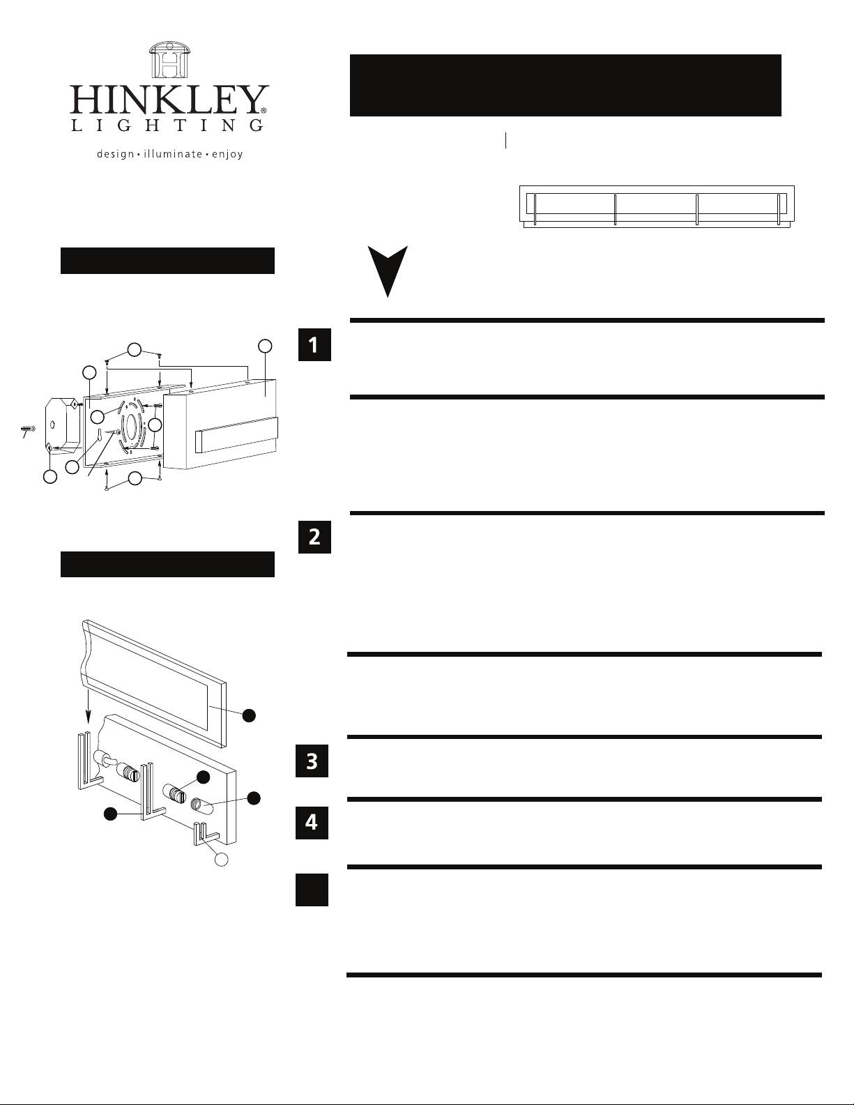
Drawing 1 - Fixture Mounting
assembly instructions
5656
Family: Latitude Item No. 5656
start here
wall
anchor
C
A
D
G
E
anchor
screw
Drawing 2 - Fixture Assembly
F
C
B
3
1. Find a clear area in which you can work.
2. Unpack fixture and glass from carton.
3. Carefully review instructions prior to assembly.
*** The construction of this fixture will be accomplished by first mounting the
mounting strap to the junction box, making all necessary electrical connections,
assembling the main body of the fixture, mounting the fixture to the wall,
and then installing the glass.
1. Remove main mounting plate (A) from fixture back plate (B) by removing the four
flat head screws (C) - see Drawing 1.
2. Slide the wires from the junction box, through the large center hole, making sure
curved slots (D) line up with the threaded holes (E) in the junction box.
3. Using two 8-32 screws (F) attach the main mounting plate (A) to the junction box,
making sure side of mounting plate (A) is square to ceiling.
4. Additional wall anchors supplied can be installed at keyhole points
SAFETY WARNING: READ WIRING AND GROUNDING INSTRUCTIONS (I.S. 18)
AND ANY ADDITIONAL DIRECTIONS. TURN POWER SUPPLY OFF DURING
INSTALLATION. IF NEW WIRING IS REQUIRED, CONSULT A QUALIFIED
ELECTRICIAN OR LOCAL AUTHORITIES FOR CODE REQUIREMENTS.
(G)
.
Make electrical connections from supply wire to fixture lead wires. Refer to instruction
1
2
4
P
5
HIN K LEY L I GHTIN G 33000 Pin O ak Par kway, A vo n Lake, OH 44 01 2 800.4 46.5539 / 4 40 .653 .550 0 hinkl eylig ht ing.com
sheet (I.S. 18) and follow all instructions to make all necessary wiring connections.
Then refer back to this sheet to continue installation of this fixture.
1. Mount the fixture by sliding the back plate (B) over mounting plate (A) - see
Drawing 1.
2. Attach the back plate (B) to the mounting plate (A) using the screws (C).
1. Fixture can be lamped accordingly prior to installing the glass.
2. After installing the lamp thread bulb shield (1) onto socket (2).
3. To install glass (3) slide panel between uprights (4) with etched side facing toward
the bulb. Optional padding material is provided and can be cut to size and placed at
base of uprights (P) were the glass rest.
06.01.13
 Loading...