

Page 1
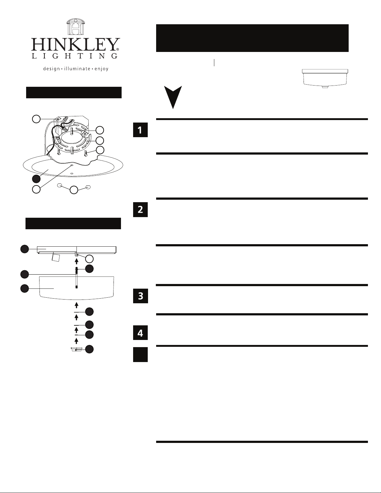
Drawing 1 - Fixture Mounting
J
B
A
C
1
D
Drawing 2 - Glass Installation
F
assembly instructions
5421
Family: Ocho Item No. 5421 CM
start here
1. Find a clear area in which you can work.
2. Unpack fixture and glass from carton.
3. Carefully review instructions prior to assembly.
*** The construction of this fixture will be accomplished by first mounting the
mounting strap to the junction box, making all necessary electrical connections,
hanging the fixture from the ceiling, and then installing the fixture glass.
1. Prepare mounting disc (A) by threading two screws (B) provided into the back of the
mounting strap (A) - see Drawing 1.
• Be sure the holes into which the screws are threaded match the spacing of holes (D)
in the canopy (E).
2. Attach mounting disc (A) to junction box (J) using two 1” screws (C) provided.
1
A
3
2
4
SAFETY WARNING: READ WIRING AND GROUNDING INSTRUCTIONS (I.S. 18)
AND ANY ADDITIONAL DIRECTIONS. TURN POWER SUPPLY OFF DURING
INSTALLATION. IF NEW WIRING IS REQUIRED, CONSULT A QUALIFIED
ELECTRICIAN OR LOCAL AUTHORITIES FOR CODE REQUIREMENTS.
Make electrical connections from supply wire to fixture lead wires. Refer to instruction
sheet (I.S. 18) and follow all instructions to make all necessary wiring connections.
Then refer back to this sheet to continue installation of this fixture.
5
6
7
8
5
1. Hang the fixture by slipping the holes (D) in the ceiling pan (1) over the screws (B) in
the mounting disc (A) - see Drawing 1.
2. Thread on ball knobs (F) to secure fixture to ceiling.
1. To install glass, thread center stem (2) into coupler (A) located in the center of the
ceiling pan (1) - see Drawing 2.
2. Using a 9/16” wrench, tighten hex nut (3) up against coupler (A) to lock center
stem (2) in place.
3. Fixture can now be lamped accordingly.
4. Slip glass (4) onto center stem (2) and hold in position.
5. Slip rubber washer (5) onto center stem (2) and hold in position.
6. Slip metal washer (6) onto center stem (2) and hold in position.
7. Thread hex nut (7) onto center stem (2) and tighten.
Note: Over tightening could cause damage to glass.
8. Thread bottom cap (8) onto end of center stem (2) and tighten.
HINKLEY LIGHTING 33000 Pin Oak Parkway, Avon Lake, OH 44012 800.446.5539 / 440.653.5500 hinkleylighting.com
Page 2
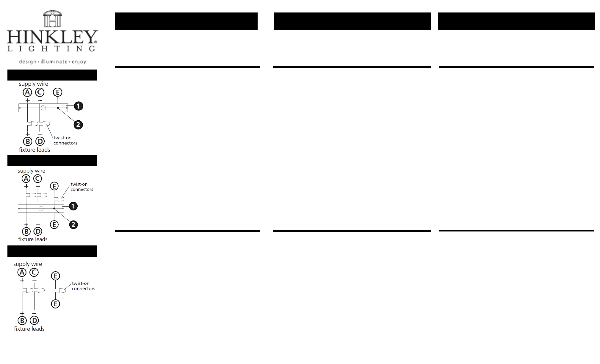
Drawing 1 – Flush Mount
Drawing 2 – Chain Hung
Drawing 3 – Post-Mount
I.S. 18
wiring grounding instructions
SAFETY WARNING: READ WIRING AND GROUNDING
INSTRUCTIONS (IS 18) AND ANY ADDITIONAL DIRECTIONS.
TURN POWER SUPPLY OFF DURING INSTALLATION. IF NEW
WIRING IS REQUIRED, CONSULT A QUALIFIED ELECTRICIAN OR
LOCAL AUTHORITIES FOR CODE REQUIREMENTS
I.S. 18
câblage échouage instructions
AVERTISSEMENT DE SECURITE: LIRE CABLAGE ET INSTRUCTIONS DE
MISE (IS 18), ET TOUTE AUTRE INSTRUCTION. COUPER L’ALIMENTATION
ELECTRIQUE PENDANT L’ONSTALLATION. SI DE NOUVELLES CABLAGE
N’EST NECESSAIRE, CONSULTEZ UN ELECTRICIEN QUALIFIE OU
AUTORITES LOCALES POUR EXIGENCES DU CODE.
wiring instructions
Indoor Fixtures
1. Connect positive supply wire (A) (typically black or the smooth,
unmarked side of the two-conductor cord) to positive fixture lead (B)
with appropriately sized twist on connector - see Drawings 1 or 2.
2. Connect negative supply wire (C) (typically white or the ribbed, marked
side of the two-conductor cord) to negative fixture lead (D).
3. Please refer to the grounding instructions below to complete all
electrical connections
Outdoor Fixtures
1. Connect positive supply wire (A) (typically black or the smooth
unmarked side of the two-conductor cord) to positive fixture lead (B)
with appropriately sized twist on connector --- see Drawings 2 or 3.
2. Connect negative supply wire (C) (typically white or the ribbed, marked
side of the two-conductor cord) to negative fixture lead (D).
3. Cover open end of connectors with silicone sealant to form a
watertight seal.
If installing a wall mount fixture, use caulk to seal gaps between the
fixture mounting plate (backplate) and the wall. This will help prevent
water from entering the outlet box. If the wall surface is lap siding, use
caulk and a fixture mounting platform specially.
4. Please refer to the grounding instructions below to complete all
electrical connections.
instructions de câblage
Luminaires Itérieurs
1. Brancher le fil d’alimentation positive (A) (généralement noir ou, côté lisse
banalisée de la corde á deux conducteurs) á plob de fixation positive (B) avec
la torsion de taille appropriée sur le connecteur --- Voir Schéma 1 ou 2.
2. Connecter le fil d’alimentation négative (C) (généralement blanc ou l’, côté
marqué nervurée du fil á deux conducteurs) au conducteur négatif de
l’appareil (D).
3. S’il vous plaît se référer á la mise á la terre instructions ci-dessous pour
terminer toutes les connexions électriques.
Luminaires Extérieurs
1. Brancher le fil d’alimentation positive (A) (généralement noir ou le côté lisse
banalisée de la corde á deux conducteurs) á plomb de fixation positive (B)
avec la torsion approrpriately taille du connecteur --- Voir Schéma 2 ou 3.
2. Connecter le fil d’alimentation négative (C) (généralement blanc ou l’, côté
marqué nervurée du fil á deux conducteurs) au conducteur négatif de
l’appareild (D).
3. Couvrir extrémité ouverte de connecteurs acex du silicone pour former un
joint étenche á l’eau.
Si l’installation d’un luminaire de montage mural, utiliser calfeutrage pour
sceller l’espace entre la plaque de montage de fixation (plaque arriére) et la
paroi. Cela aidera á empêcher l’eau de pénétrer dans le boc sortie. Si la
surface du mur est bardage á clin, utiliser caldeutrage et une plate-forme de
montage d’appareils spécialement.
4. S’il vous plait se referrer auc instructions ci-dessous pour terminer la terre
toutes les connexions électrques.
grounding instructions
Flush Mount Fixtures
For positive grounding in a 3-wire electrical system, fasten the fixture
ground wire (E) (typically copper or green plastic coated) to the fixture
mounting strap (M) with the ground screw (S) - see Drawing 1.
Note: On straps for screw supported fixtures, first install the two mounting
screws in strap. Any remaining tapped hole may be used for the ground screw.
Chain Hung Fixtures
Loop fixture ground wire (E) (typically copper or green plastic coated)
under the head of the ground screw (S) on fixture mounting strap (M)
and connect to the loose end of the fixture ground wire directly to the
ground wire of the building system with appropriately sized twist-on
connectors - see Drawing 2.
Post-Mount Fixtures
Connect fixture ground wire (E) (typically copper or green plastic coated)
to power supply ground with appropriately sized twist-on connector
inside post. Cover open end of connector with silicone sealant to form a
watertight seal - see Drawing 3.
instructions de mise
Montage Encastré Fixtures
Pour la terre positive dans un systéme électrique á 3 fils, fixez le fil de terre du
luminaire (E) (généralement en cuivre ou vert recouvert de plastique) á la sangle
de fixation de fixation (M) avec la vis de terre (S) --- Voir Schéma 1.
Remarque: Sur les sangles pour les appareils pris en charge á vis, installez d’abord les
deux vis de fixation á sangle. Tout trou taraudé restante peut être utilisée pour la vis de
terre.
Chaîne Accroché Luminaires
Boucle fil du luminaire au sol (E) (généralement en cuivre ou vert recouvert de
plastique) sous la tête de la vis de terre (S) sur la sangle de fixation de fixation
(M) et se connecter á l’extrémitré libre du fil de terre du luminaire directement
sur le fil de terre du systéme de construction avec une taille appropriée
connecteurs á visser --- Voir Schéma 2.
Luminaires Aprés Montage
Brancher le fil de terre du luminaire (E) (généralement en cuivre ou vert
recouvert de plastique) á la masse de l’alimentation avec une taille appropriée
torsion sur le connecteur á l’intérieur de la poste. Couvrir extrémité ouverte du
connecteur avec du mastic silicone pour former un joint étache á l’eau --- Voir
Schéma 3.
I.S. 18 tierra cableado instrucciones
ADVERTENCIA DE SEGURIDAD: LEA LAS INSTRUCCIONES DE CABLEADO
Y LA TIERRA (IS 18), E INSTRUCCIONES ADICIONALES. APAUGE LA
ALIMENTACIÓN DE CORRIENTE DURANTE LA INSTALACIÓN. SI SE
REQUIERE NUEVO CABLEADO, CONSULTE CON UN ELECTRICISTA O
AUTHORIDADES LOCALES PARA REQUISITOS DEL CÓDIGO
Instrucciones de cableado
Acesorios Cubierta
1. Conecte el cable de alimentación positive (A) (normalmente negro o la cara
lisa, sin marcas del cable de dos conductores) de plomo accesorio positivo (B)
con un giro de tamaño adecuado en el conector --- Véase la Figura 1 y 2.
2. Conecte el cable de alimentación negativa (C) (por lo general de color
blanco o el lado marcado estriado del cable de dos conductores) de plomo
accesorio negativo (D).
3. Por favor, consulte las instrucciones de puesta a tierra-a continuación para
completar todas las conexiones eléctricas.
Accesorios Exterior
1. Conecte el cable de alimentación positiva (A) (normalmente negro el lado no
marcado suave del cable de dos conductores) de plomo accesorio positivo (B)
con un giro de tamaño approrpriately conector --- Véase la Figura 2 y 3.
2. Conecte el cable de alimentación negative (C) (por lo general de color
blanco o el lado marcado estriado del cable de dos conductores) de plomo
accesorio negativo (D).
3. Cubra el extreme abierto de conectores con sellador de silicona poara formar
un sello hermético.
Si va a instalar un soporte de fijación mural, use masilla para sella los
espacios entre la placa de montaje del aparato (placa) y la pared. Esto
ayudará a evitar que el agua entre en la boc salida. Si la superficie de la
pared es de revestimiento solapado, utilice masilla y una plataforma de
montaje accesorio especial.
4. Por favor, consulte las Instrucciones de puesta a tierra-a continuación para
completar todas las conexiones eléctricas.
instrucciones puesta a tierra
Montaje Embutido Accesorios
Para conectar a tierra en un sistema eléctrico de 3 hilos, fije el cable de tierra
del artefacto (E) (generalmente de cobre o verde recubierto de plástico) a la
brida de montaje accesorio (M) con el tornillo de tierra (S) --- Véase la Figura 1.
Nota : En las correas de accesorios compatibles tornillos, primero instale los dos
tornillos de montaje de la correa. Cualquier agujero roscado restante puede ser
utilizado para el tornillo de tierra.
Cadena Hung Accesorios
Loop alambre de tierra (E) (generalmente de cobre o verde recubierto de
plático) debajo de la cabeza del tornillo de tierra (S) en la brida de montaje
accesorio (M) y conectar con el extremo suelto del cable de tierra luminaria
directamente al cable de tierra del sistema de construcción con un tamaño
adecuado twist-conectores --- Véase la Figura 2.
Accesorios Posterior Monte
Conecte el cable de tierra del artefacto (E) (generalmente de cobre o verde
recubierto de plástico) a tierra de la fuente de alimentacón con conector de
tamanño adecuado en el interior puesto enlaces en forma. Cubra el extremo
abierto del conector con sellador de silicona para formar un sello hermético --Véase la Figura 3.
H I N K L E Y L I G H T I N G 33000 Pin Oak Parkway Avon Lake, OH 44012 800.446.5539 / 440.653.5500 hinkleylighting.com
 Loading...