

Page 1
assembly instructions
Item No. 52700
52700
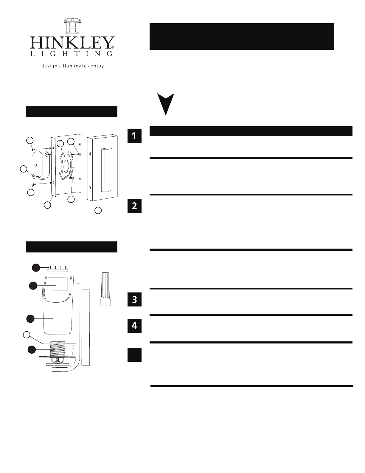
Drawing 1 - Fixture Mounting
C
E
C
A
Drawing 2 - Glass installation
F
D
F
2
3
4
R
B
socket
tool
start here
1. Find a clear area in which you can work.
2. Unpack xture and glass from carton.
3. Carefully review instructions prior to assembly.
*** The construction of this xture will be accomplished by rst mounting the
mounting strap to the junction box, making all necessary electrical connections, assembling the main body of the xture, mounting the xture to the wall,
and then installing the glass.
1. Remove main mounting plate (A) from xture back plate (B) by removing the four at head
screws (C) - see Drawing 1.
2. Slide the wires from the junction box, through the large center hole, making sure curved slots
(D) line up with the threaded holes (E) in the junction box.
3. Using two 8-32 screws (F) attach the main mounting plate (A) to the junction box, making sure
side of mounting plate (A) is square to ceiling.
SAFETY WARNING: READ WIRING AND GROUNDING INSTRUCTIONS (I.S. 18)
AND ANY ADDITIONAL DIRECTIONS. TURN POWER SUPPLY OFF DURING
INSTALLATION. IF NEW WIRING IS REQUIRED, CONSULT A QUALIFIED
ELECTRICIAN OR LOCAL AUTHORITIES FOR CODE REQUIREMENTS.
Make electrical connections from supply wire to xture lead wires. Refer to instruction sheet (I.S.
18) and follow all instructions to make all necessary wiring connections. Then refer back to this
sheet to continue installation of this xture.
1. Mount the xture by sliding the back plate (B) over mounting plate (A) - see Drawing 1.
2. Attach the back plate (B) to the mounting plate (A) using the screws (C).
1
5
HINKLEY LIGHTING 33000 Pin Oak Parkway Avon Lake, Ohio 44012 800-446-5539 www.hinkleylighting.com
1. To install glass remove socket ring (2) and spacer (3) from socket (1).
2. Slip glass (4) over socket (1) and through rings (R) on xture.
3. Slip spacer (3) over socket.
4. Thread socket ring (2) onto socket (1) and tighten until snug, using socket ring tool provided.
6.1.12
 Loading...