

Page 1
UNION
52372 / 52373 / 52374
Bulbs: 60 W g9
ASSEMBLY INSTRUCTIONS
Assembly of this fixture will be accomplished by first installing the mounting strap to
the junction box, making all necessary electrical connections, mounting the fixture to
the wall and then installing the fixture glass.
SAFETY WARNING: Read wiring and grounding instructions (IS18)
and any additional directions. Turn power supply off during installation. If new wiring
is required, consult a qualified electrician or local authorities for code requirements.
STEP 1
NOTE: The union fixture can be mounted vertically or horizontally. The attitude in
which the fixture is to be installed must be determined prior to installation. To install
vertically retainer plate (a) must be mounted with long edge perpendicular to the ceiling
and then follow installation instructions below.
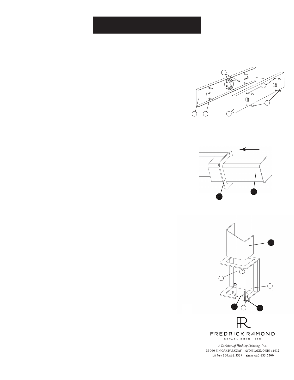
1 Remove ball knob (c) from front of backplate (d) - See Drawing 1.
2 Remove retainer plate (a) from backplate (d).
3 Attach retainer plate (a) to junction box using two 8-32 screws (b).
If installing vertical long edge is perpendicular to ceiling, if installing horizon
tally long edge is parallel to ceiling.
4 Additional screws can be installed at points (e) for additional mounting support.
Please use appropriate anchor for material the fixture is being mounted too.
5 Make electrical connections from supply wire to fixture lead wires. Refer to
instruction sheet (IS18) and follow all instructions to make all necessary
wiring connections. Then refer back to this sheet to continue installation of
this fixture.
6 Slip holes (g) in backplate (d) over screws (f) on retainer plate (a).
7 Thread ball knobs (c) onto end of screws (f) and tighten to secure backplate to
wall.
[DRAWING 1]
b
g
c
a
f
d
[DRAWING 2]
1
2
[DRAWING 3]
STEP 2
1 If mounted horizontally slip class (1) through arch (2) from either end, and
center - See Drawing 2.
STEP 3
1 To install glass vertically first it is necessary to attach the glass supports (3) to the
backplate (d) -See Drawing 3.
2 To install glass supports (3) first remove screw (4) from backplate (d).
3 To attach glass supports (3) align holes in support tab with threaded hold (g) in
backplate (d) and thread in screw (3) removed earlier.
NOTE: there is a left and right glass support. when installing support, hook (h) and
mounting tab of glass support face towards the outside edge of the fixture - S ee
Drawing 3.
4 After glass supports are attached slide in glass (1) in from the top of the fixture,
through arch (2)making sure bottom edge of glass fits into hook (h) of glass support.
1
d
g
4
h
3
06.01.13
 Loading...