

Page 1
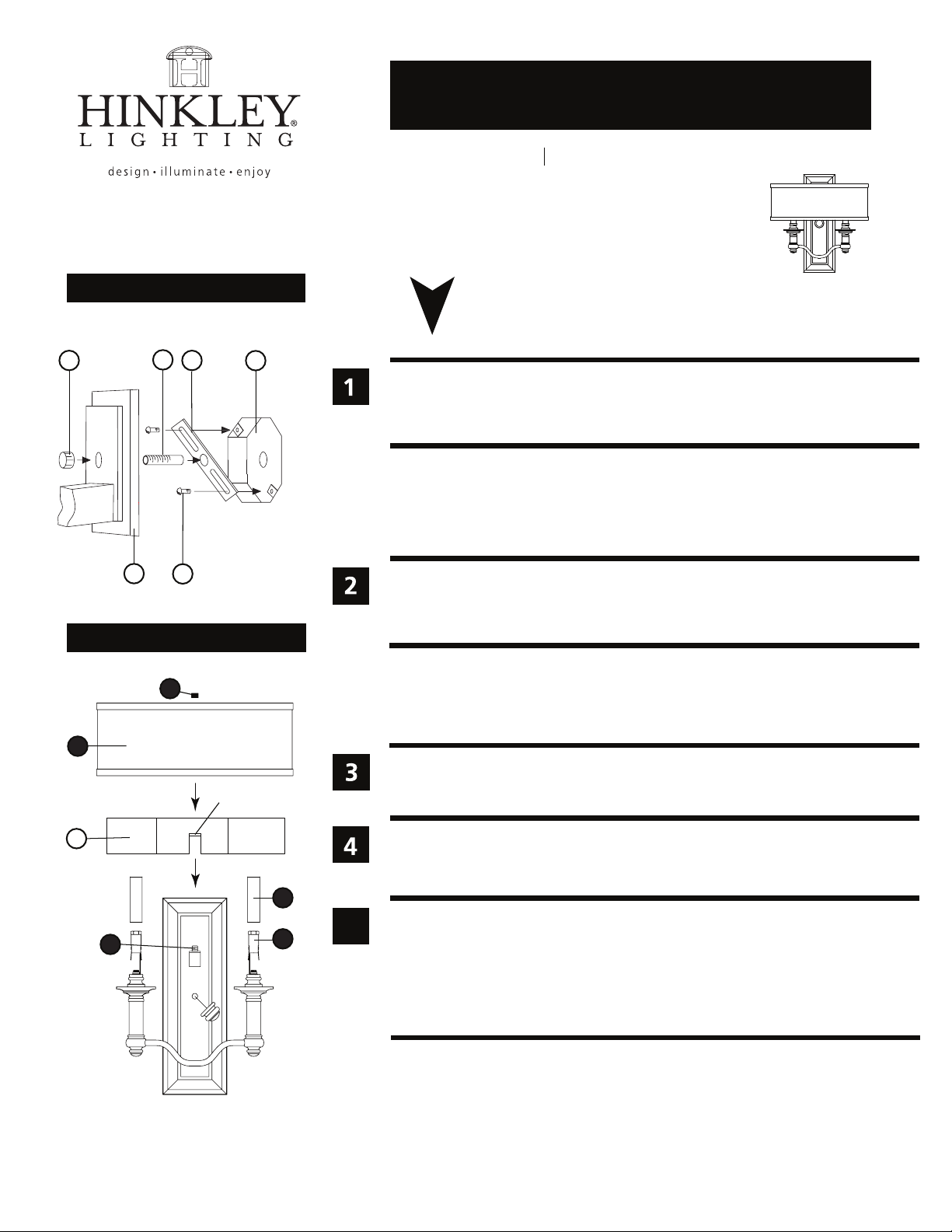
Drawing 1 - Fixture Mounting
A
D
C
assembly instructions
4900
Family: Sussex Item No. 4900 EZ/BN
start here
J
1. Find a clear area in which you can work.
2. Unpack fixture and glass from carton.
3. Carefully review instructions prior to assembly.
*** The construction of this fixture will be accomplished by first attaching the
mounting strap to the junction box, making all necessary electrical connections,
mounting the fixture to the wall and then installing the fixture shade.
E
Drawing 2 - Shade Installation
B
3
1
CENTER TAB
G
2
1. Prepare mounting strap (A) by threading 1-5/8” nipple into the center hole of the
mounting strap (A), approximately 1/4“- see Drawing 1.
2. Attach mounting strap (A) to junction box (J) using two 1” screws (C) provided.
SAFETY WARNING: READ WIRING AND GROUNDING INSTRUCTIONS (I.S. 18)
AND ANY ADDITIONAL DIRECTIONS. TURN POWER SUPPLY OFF DURING
INSTALLATION. IF NEW WIRING IS REQUIRED, CONSULT A QUALIFIED
ELECTRICIAN OR LOCAL AUTHORITIES FOR CODE REQUIREMENTS.
Make electrical connections from supply wire to fixture lead wires. Refer to instruction
sheet (I.S. 18) and follow all instructions to make all necessary wiring connections.
Then refer back to this sheet to continue installation of this fixture.
1. To mount fixture, slip center hole of backplate (E) over nipple (C) and hold fixture in
position - see Drawing 1.
2. Thread decorative knob (D) onto end of nipple (C) and tighten to secure fixture.
4
1. To install shade and wall guard, first place hole in center tab of wall guard (G) onto
5
5
threaded tube (2) - see Drawing 2.
2. Place shade (1) onto nipple (2) and secure with cap nut (3) - see Drawing 2.
3. Slip candle cover (4) onto socket (5).
4. Fixture can now be lamped accordingly.
Note: Maximum wattage for 4900 fixture is 60 watts per bulb.
2.20.09
HINKLEY LIGHTING 12600 Berea Road Cleveland, OH 44111 800.446.5539 / 216.671.3300 www.hinkleylighting.com
 Loading...