

Page 1
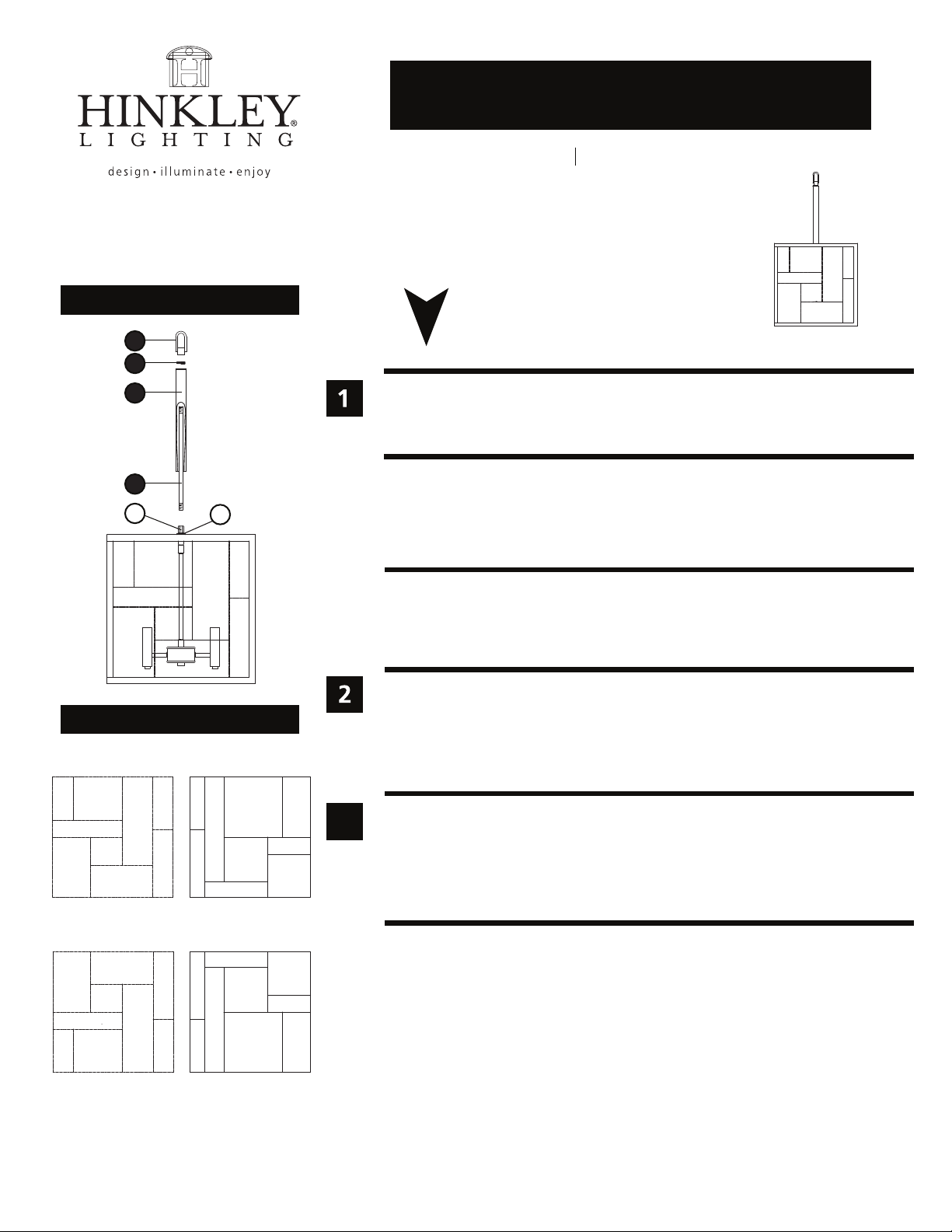
Drawing 1 - Fixture Assembly
H I N K L E Y L I G H T I N G 33000 Pin Oak Parkway Avon Lake, OH 44012 800.446.5539 / 440.653.5500 hinkleylighting.com
assembly instructions
4574
Family: Mondrian Item No. 4574 KZ
4
3
2
1
A
Drawing 2 - Glass Installation
top of panel
water glass
water glass
clear seedy
water glass
water
glass
clear seedy
panel 1
clear seedy clear seedy
water glass
white glass white glass
clear seedy
water glass
white glass
clear seedy
B
clear seedy
white
glass
panel 2
water glass
clear seedy
water
glass
3
start here
1. Find a clear area in which you can work.
2. Unpack fixture and glass from carton.
3. Carefully review instructions prior to assembly.
*** The construction of this fixture will be accomplished by first assembling
the fixture, installing the fixture glass, installing the mounting bracket to the
junction box, making all necessary electrical connections and hanging the
fixture from the ceiling.
SAFETY WARNING: READ WIRING AND GROUNDING INSTRUCTIONS (I.S. 18)
AND ANY ADDITIONAL DIRECTIONS. TURN POWER SUPPLY OFF DURING
INSTALLATION. IF NEW WIRING IS REQUIRED, CONSULT A QUALIFIED
ELECTRICIAN OR LOCAL AUTHORITIES FOR CODE REQUIREMENTS.
1. To assemble fixture, thread center tube (1) into coupler (A) approximately 3/8” - see
Drawing 1.
2. Slip square tube (2) over center tube (1) and fit over square base (B).
3. Thread knurl nut (3) onto center tube (1) and tighten.
4. Thread loop (4) onto end of center tube (1) and tighten.
1. To install glass panels, unwrap and organize glass panels - see Drawing 2.
• Note: Center column is on swivel. After glass is installed caution must be used when
moving the fixture so stem does not swivel and break glass.
2. Refer to glass installation instruction sheet provided. Then refer to the hanging
instruction sheet (I.S. 19) provided to hang this fixture. Then fixture can be lamped
accordingly.
water glass
clear seedy
white
glass
water glass
clear seedy
water glass
white
glass
panel 3 panel 4
bottom of panel
clear seedy
white glass
water glass
clear seedy
white
glass
clear seedy
water
glass
clear seedy
water glass
3.23.10
Page 2
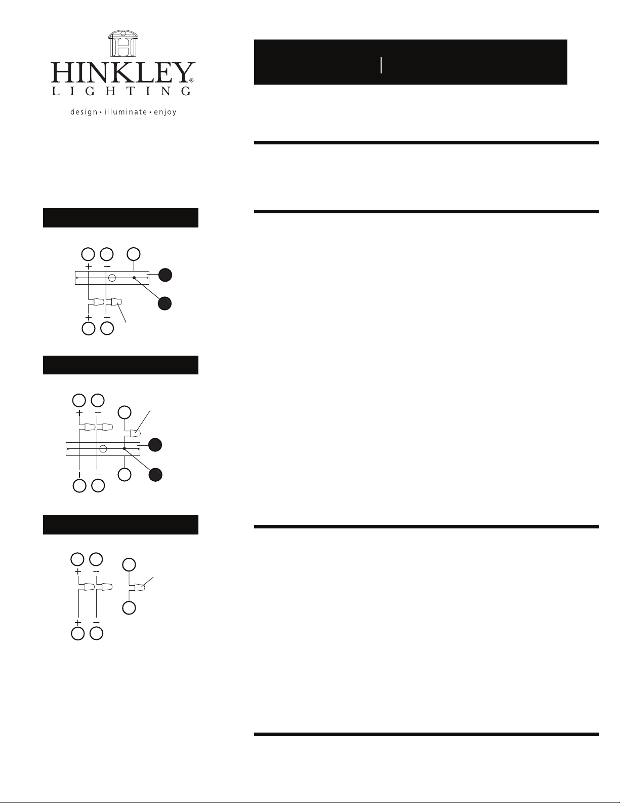
Drawing 1 - Flush Mount
H I N K L E Y L I G H T I N G 33000 Pin Oak Parkway Avon Lake, OH 44012 800.446.5539 / 440.653.5500 hinkleylighting.com
supply wire
A CC
E
I.S. 18 wiring grounding instructions
I.S. 18
SAFETY WARNING: READ WIRING AND GROUNDING INSTRUCTIONS (I.S. 18)
AND ANY ADDITIONAL DIRECTIONS. TURN POWER SUPPLY OFF DURING
INSTALLATION. IF NEW WIRING IS REQUIRED, CONSULT A QUALIFIED
ELECTRICIAN OR LOCAL AUTHORITIES FOR CODE REQUIREMENTS.
wiring instructions
Indoor Fixtures
B
fixture leads
Drawing 2 - Chain Hung
supply wire
connectors
twist-on
D
A C
twist-on
E
E
connectors
1
E
E
D
B
fixture leads
Drawing 3 - Post-Mount
supply wire
A C
2
E
twist-on
connectors
E
D
B
fixture leads
1
2
1. Connect positive supply wire (A) (typically black or the smooth, unmarked
side of the two-conductor cord) to positive fixture lead (B) with appropriately
sized twist on connector - see Drawings 1 or 2.
2. Connect negative supply wire (C) (typically white or the ribbed, marked
side of the two-conductor cord) to negative fixture lead (D).
3. Please refer to the grounding instructions below to complete all
electrical connections.
Outdoor Fixtures
1. Connect positive supply wire (A) (typically black or the smooth unmarked
side of the two-conductor cord) to positive fixture lead (B) with appropriately
sized twist on connector - see Drawings 2 or 3.
2. Connect negative supply wire (C) (typically white or the ribbed, marked
side of the two-conductor cord) to negative fixture lead (D).
3. Cover open end of connectors with silicone sealant to form a watertight seal.
• If installing a wall mount fixture, use caulk to seal gaps between the fixture
mounting plate (backplate) and the wall. This will help prevent water from
entering the outlet box. If the wall surface is lap siding, use caulk and a
fixture mounting platform specially.
4. Please refer to the grounding instructions below to complete all
electrical connections.
grounding instructions
Flush Mount Fixtures
For positive grounding in a 3-wire electrical system, fasten the fixture ground
wire (E) (typically copper or green plastic coated) to the fixture mounting strap (1)
with the ground screw (2) - see Drawing 1.
Note: On straps for screw supported fixtures, first install the two mounting screws in strap.
Any remaining tapped hole may be used for the ground screw.
Chain Hung Fixtures
Loop fixture ground wire (E) (typically copper or green plastic coated) under the
head of the ground screw (2) on fixture mounting strap (1) and connect to the
loose end of the fixture ground wire directly to the ground wire of the building
system with appropriately sized twist-on connectors - see Drawing 2.
Post-Mount Fixtures
Connect fixture ground wire (E) (typically copper or green plastic coated) to power
supply ground with appropriately sized twist-on connector inside post. Cover open
end of connector with silicone sealant to form a watertight seal - see Drawing 3.
 Loading...