

Page 1
Drawing 1 - Assembly
H I N K L E Y L I G H T I N G 33000 Pin Oak Parkway Avon Lake, OH 44012 800.446.5539 / 440.653.5500 hinkleylighting.com
assembly instructions
3878
Family: Meridian Item No. 3878 BN
60º
A
A
A
Drawing 2 - Assembly
A
A
A
CHAIN
E
D
B
C
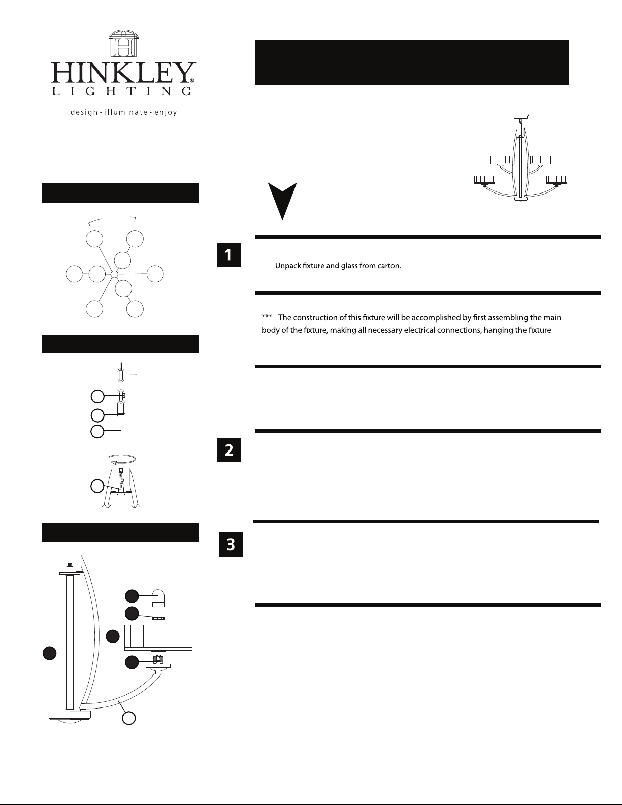
start here
1. Find a clear area in which you can work.
2.
3. Carefully review instructions prior to assembly.
from the ceiling, and then installing the glass.
SAFETY WARNING: READ WIRING AND GROUNDING INSTRUCTIONS (I.S. 18)
AND ANY ADDITIONAL DIRECTIONS. TURN POWER SUPPLY OFF DURING
INSTALLATION. IF NEW WIRING IS REQUIRED, CONSULT A QUALIFIED
ELECTRICIAN OR LOCAL AUTHORITIES FOR CODE REQUIREMENTS.
1. To assemble main body, spread arms (A)
they are equally spaced 60 degrees apart - see Drawings 1 & 3.
Slid stem along wire and thread onto thread stud (C) -
2. (B)
3. Please refer to the hanging instruction sheet (I.S. 19-50)
refer back to this sheet to install glass.
4. Use quick link (E) to connect chain to fixture loop.
located on the main body assembly
see Drawing 2
.
Then
(1), until
Drawing 3 - Glass Installation
5
2
1. To install glass, remove socket ring
2. Slip glass
3. Thread socket ring
Fixture can now be lamped accordingly.
4.
Thread bulb shield
5.
(3)
over socket
(4)
.
(2) onto socket (4) to secure glass (3)
(5) onto socket until snug.
(2)
from socket (4)- see Drawing 3
.
3
1
4
A
.
08.03.10R
Page 2
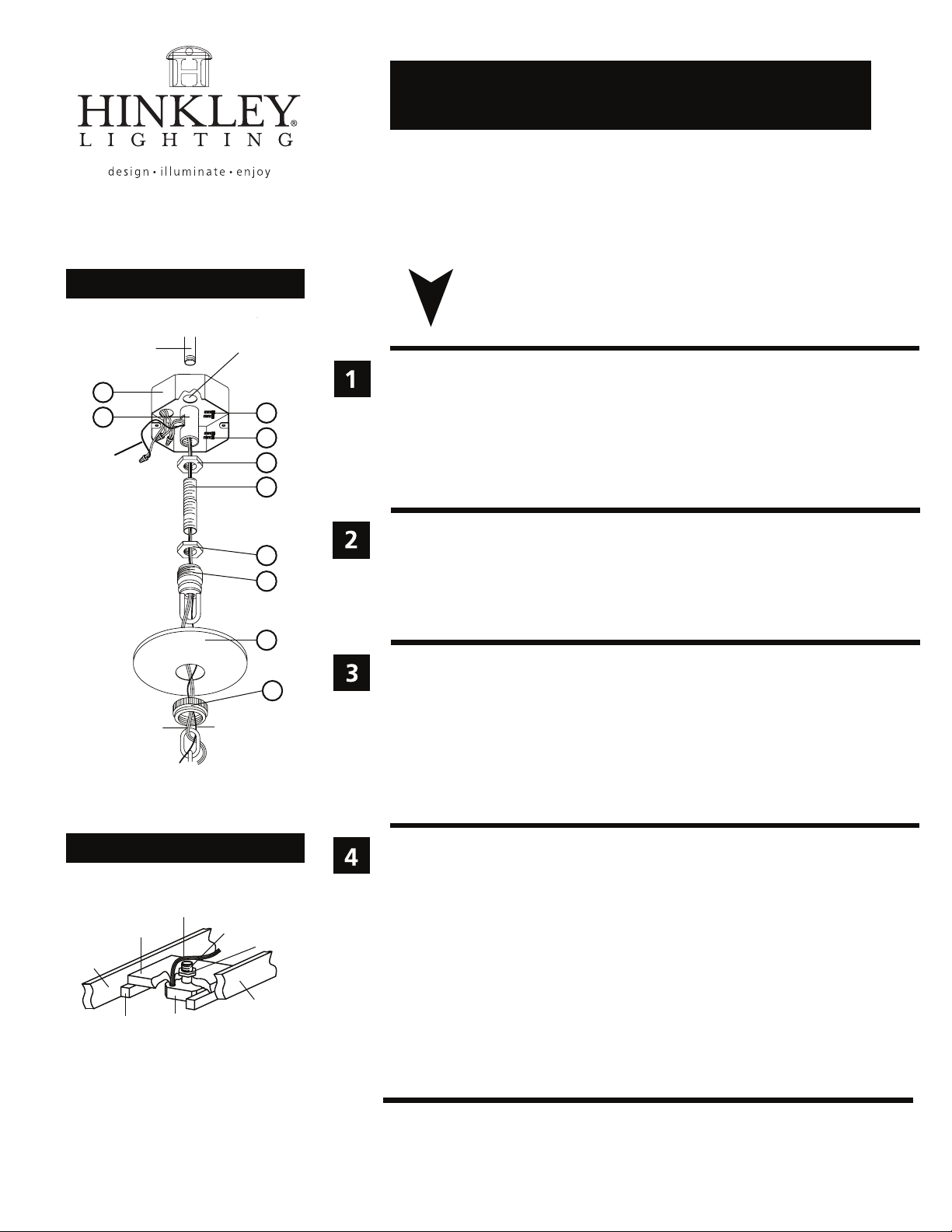
Drawing 1 - Fixture Assembly
3/8 steel pipe
A
B
ground
wire
top center
knockout
C
F
D
E
J
K
L
I.S. 19-50C hanging instructions
I.S. 19-50C
Hanging instructions for 3 tier fixture under 50 lbs.
start here
1. Shut off electrical current before starting. If the fixture you are replacing is
turned on and off by a wall switch, simply turn the switch off. If not, remove
the appropriate fuse (or open the circut breakers) until the fixture is dead.
• DO NOT RESTORE CURRENT - EITHER BY FUSE, BREAKER, OR SWITCH -
UNTIL THE NEW FIXTURE IS COMPLETELY WIRED AND IN PLACE.
2. Supply wires shall enter the outlet box (A) through any knockout EXCEPT
the top center knockout - see Drawing 1.
1. Fixture is to be mounted by a 3/8 steel pipe with 3/8 -18 NPSM thread, 3/4”
threads at both ends (not supplied). Pipe should be anchored to structure or
bridging member with sufficient strength to support 4 times the fixtures
weight - see Drawing 2.
2. Adjust pipe so 1/2” of 3/8 steel pipe extends into the junction box, at the
center knock out.
wire
Drawing 2 - Installation Example
bridge
ceiling
joist
support
block
junction
box
ground
wire
from fixture
supply wire
3/8 steel pipe
ceiling
joist
M
hex nut
1. Thread pipe coupler (B) onto protruding pipe inside outlet box. Secure in place by
tightening allen head screw (C) - see Drawing 1.
2. Thread hexnut (D) onto threaded nipple (E). Thread nipple (E) into coupler (B).
Secure in place by tightening hexnut (D) against coupler (B) and then tightening
allen screw (F).
3. Thread hexnut (J) onto nipple (E). DO NOT tighten hexnuts (J) at this time.
4. Thread screw collar loop (K). Adjust loop height so the half of the exterior thread
on screw collar loop (K) is exposed when canopy (L) is held up to the ceiling.
1. Determine length of chain you will require. Attach one end of length of chain to fixture.
2. Slip threaded ring (M) and canopy (L) onto chain - see Drawing 1.
3. Attach fixture with chain to screw collar loop (K
size of fixture is difficult to manage alone.
4. Weave ground wire, and supply wire, through chain, up through center
of screw collar loop (K), through center of nipple (E), and out the opening on the side
of coupler (B).
5. Make electrical connections from supply wire to fixture lead wires. Refer to instruction sheet (I.S. 18) and follow all instructions to make all necessary wiring connections
6. After connections are made slip wires into junction box. Slip canopy along chain and
up to ceiling. Thread thread ring (M) onto loop and tighten to secure canopy to
ceiling.
). Please get assistance, weight and
HINKLEY LIGHTING 33000 Pin Oak Parkway Avon Lake, OH 44012 800.446.5539 / 440.653.5500 hinkleylighting.com
Page 3

Drawing 1 - Flush Mount
H I N K L E Y L I G H T I N G 33000 Pin Oak Parkway Avon Lake, OH 44012 800.446.5539 / 440.653.5500 hinkleylighting.com
supply wire
A CC
E
I.S. 18 wiring grounding instructions
I.S. 18
SAFETY WARNING: READ WIRING AND GROUNDING INSTRUCTIONS (I.S. 18)
AND ANY ADDITIONAL DIRECTIONS. TURN POWER SUPPLY OFF DURING
INSTALLATION. IF NEW WIRING IS REQUIRED, CONSULT A QUALIFIED
ELECTRICIAN OR LOCAL AUTHORITIES FOR CODE REQUIREMENTS.
wiring instructions
Indoor Fixtures
B
fixture leads
Drawing 2 - Chain Hung
supply wire
connectors
twist-on
D
A C
twist-on
E
E
connectors
1
E
E
D
B
fixture leads
Drawing 3 - Post-Mount
supply wire
A C
2
E
twist-on
connectors
E
D
B
fixture leads
1
2
1. Connect positive supply wire (A) (typically black or the smooth, unmarked
side of the two-conductor cord) to positive fixture lead (B) with appropriately
sized twist on connector - see Drawings 1 or 2.
2. Connect negative supply wire (C) (typically white or the ribbed, marked
side of the two-conductor cord) to negative fixture lead (D).
3. Please refer to the grounding instructions below to complete all
electrical connections.
Outdoor Fixtures
1. Connect positive supply wire (A) (typically black or the smooth unmarked
side of the two-conductor cord) to positive fixture lead (B) with appropriately
sized twist on connector - see Drawings 2 or 3.
2. Connect negative supply wire (C) (typically white or the ribbed, marked
side of the two-conductor cord) to negative fixture lead (D).
3. Cover open end of connectors with silicone sealant to form a watertight seal.
• If installing a wall mount fixture, use caulk to seal gaps between the fixture
mounting plate (backplate) and the wall. This will help prevent water from
entering the outlet box. If the wall surface is lap siding, use caulk and a
fixture mounting platform specially.
4. Please refer to the grounding instructions below to complete all
electrical connections.
grounding instructions
Flush Mount Fixtures
For positive grounding in a 3-wire electrical system, fasten the fixture ground
wire (E) (typically copper or green plastic coated) to the fixture mounting strap (1)
with the ground screw (2) - see Drawing 1.
Note: On straps for screw supported fixtures, first install the two mounting screws in strap.
Any remaining tapped hole may be used for the ground screw.
Chain Hung Fixtures
Loop fixture ground wire (E) (typically copper or green plastic coated) under the
head of the ground screw (2) on fixture mounting strap (1) and connect to the
loose end of the fixture ground wire directly to the ground wire of the building
system with appropriately sized twist-on connectors - see Drawing 2.
Post-Mount Fixtures
Connect fixture ground wire (E) (typically copper or green plastic coated) to power
supply ground with appropriately sized twist-on connector inside post. Cover open
end of connector with silicone sealant to form a watertight seal - see Drawing 3.
 Loading...