

Page 1
____Assembly Instructions____
Item No. 3472 / 3473
3472
3473
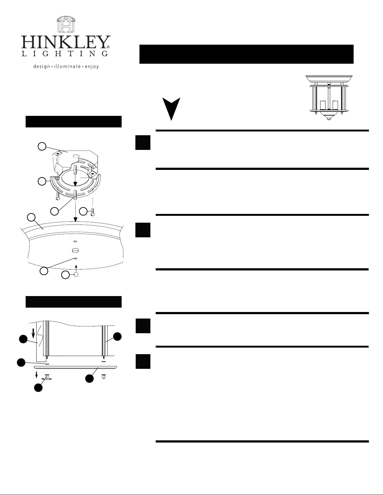
Drawing 1 - Mounting Detail
J
B
A
G
D
C
Drawing 2 - Glass replacement
E
1
2
start here
1. Find a clear area in which you can work.
2. Unpack Fixture and glass from carton.
3. Carefully Review Instructions Prior to assembly.
*** The construction of this fixture will be accomplished by first assembling the
main body of the fixture, attaching the mounting strap to the junction box,
making all necessary electrical connections, hanging the fixture from the
ceiling, installing the shade, and then installing the glass lens.
1. Prepare mounting strap (B) for mounting by installing screws (A) into mounting
plate (B) - see Drawing 1.
• Be sure the holes into which the screws are threaded match the spacing of holes (C)
in the canopy (1).
2. Attach mounting plate (B) to junction box (J), using screws (G) provided and slip
supply wires through large center hole.
SAFETY WARNING: READ WIRING AND GROUNDING INSTRUCTIONS (I.S. 18)
AND ANY ADDITIONAL DIRECTIONS. TURN POWER SUPPLY OFF DURING
INSTALLATION. IF NEW WIRING IS REQUIRED, CONSULT A QUALIFIED
ELECTRICIAN OR LOCAL AUTHORITIES FOR CODE REQUIREMENTS.
3
4
3
2
1
H I N K L E Y L I G H T I N G 33 000 Pin Oak Park way, Av o n Lak e , O H 4 4 0 1 2 800.4 46.5539 / 440.653. 5500 hinkleylightin g.com
5
4
1. Hang the fixture by slipping the mounting holes (D) in the canopy (1) over screws (B),
mounted in strap (A) previously - see Drawing 2.
2. Thread ball knobs (E) onto end of screw (B) and tighten to secrure fixture.
GLASS REPLACEMENT INSTRUTCTIONS:
1. It is recommended that the fixture be take down from the ceiling prior to replacing
the glass - see Drawing 2.
2. To replace glass first remove tear drop knobs (1) from bottom ring. Caution: if fixture
is installed when knobs are remove there is a possibility that all the glass could fall out.
3. Remove bottom ring (2), then remove rubber washers (3).
4. Slip glass (4) from between the uprights (5).
5. Replace glass (4) and re-assemble fixture by following step 1-3 in reverse order
07.12.05
Page 2
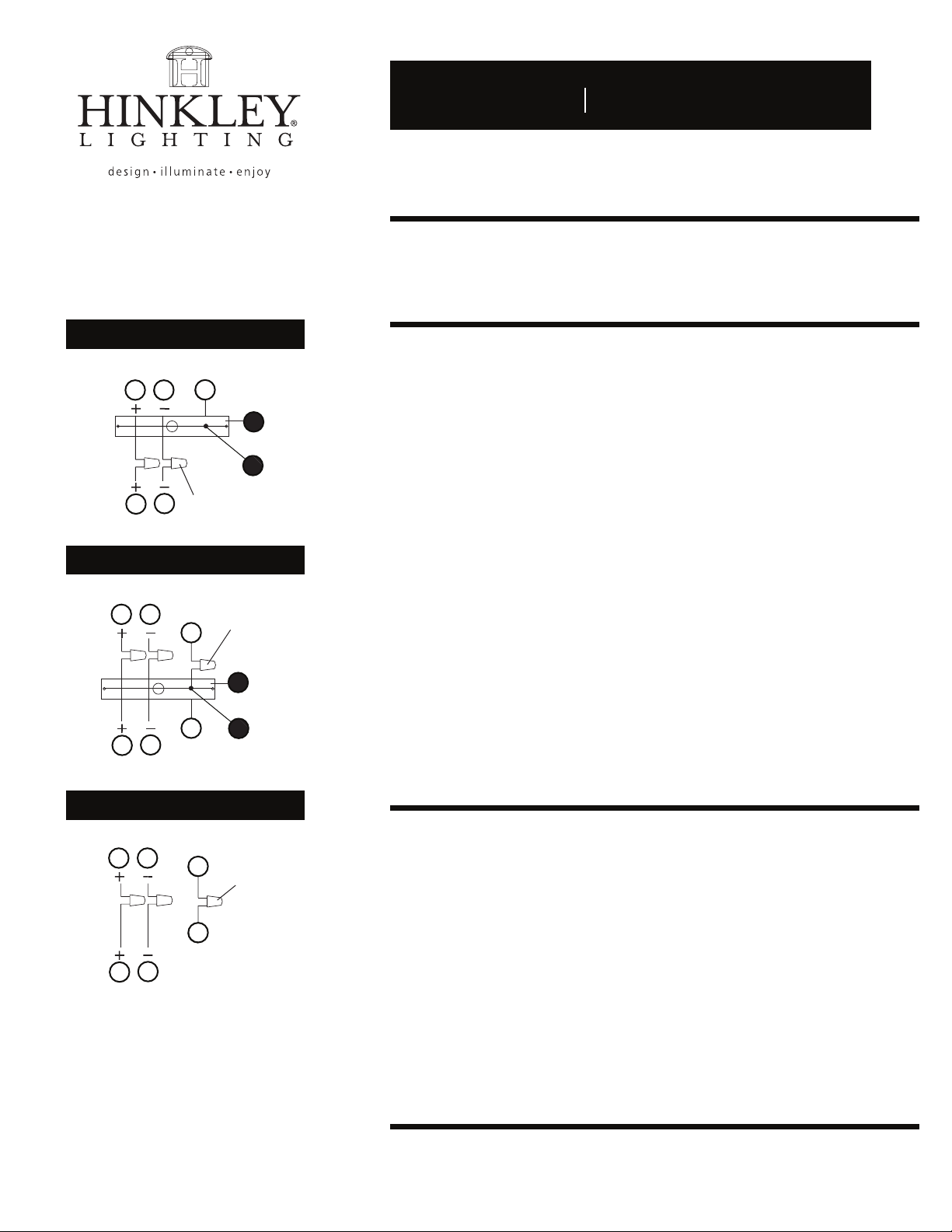
Drawing 1 - Flush Mount
supply wire
A CC
E
I.S. 18 wiring grounding instructions
I.S. 18
SAFETY WARNING: READ WIRING AND GROUNDING INSTRUCTIONS (I.S. 18)
AND ANY ADDITIONAL DIRECTIONS. TURN POWER SUPPLY OFF DURING
INSTALLATION. IF NEW WIRING IS REQUIRED, CONSULT A QUALIFIED
ELECTRICIAN OR LOCAL AUTHORITIES FOR CODE REQUIREMENTS.
wiring instructions
Indoor Fixtures
B
fixture leads
Drawing 2 - Chain Hung
supply wire
connectors
twist-on
D
A C
twist-on
E
E
connectors
1
E
E
D
B
fixture leads
Drawing 3 - Post-Mount
supply wire
A C
2
E
twist-on
connectors
E
D
B
fixture leads
1
2
1. Connect positive supply wire (A) (typically black or the smooth, unmarked
side of the two-conductor cord) to positive fixture lead (B) with appropriately
sized twist on connector - see Drawings 1 or 2.
2. Connect negative supply wire (C) (typically white or the ribbed, marked
side of the two-conductor cord) to negative fixture lead (D).
3. Please refer to the grounding instructions below to complete all
electrical connections.
Outdoor Fixtures
1. Connect positive supply wire (A) (typically black or the smooth unmarked
side of the two-conductor cord) to positive fixture lead (B) with appropriately
sized twist on connector - see Drawings 2 or 3.
2. Connect negative supply wire (C) (typically white or the ribbed, marked
side of the two-conductor cord) to negative fixture lead (D).
3. Cover open end of connectors with silicone sealant to form a watertight seal.
• If installing a wall mount fixture, use caulk to seal gaps between the fixture
mounting plate (backplate) and the wall. This will help prevent water from
entering the outlet box. If the wall surface is lap siding, use caulk and a
fixture mounting platform specially.
4. Please refer to the grounding instructions below to complete all
electrical connections.
grounding instructions
Flush Mount Fixtures
For positive grounding in a 3-wire electrical system, fasten the fixture ground
wire (E) (typically copper or green plastic coated) to the fixture mounting strap (1)
with the ground screw (2) - see Drawing 1.
Note: On straps for screw supported fixtures, first install the two mounting screws in strap.
Any remaining tapped hole may be used for the ground screw.
Chain Hung Fixtures
Loop fixture ground wire (E) (typically copper or green plastic coated) under the
head of the ground screw (2) on fixture mounting strap (1) and connect to the
loose end of the fixture ground wire directly to the ground wire of the building
system with appropriately sized twist-on connectors - see Drawing 2.
Post-Mount Fixtures
Connect fixture ground wire (E) (typically copper or green plastic coated) to power
supply ground with appropriately sized twist-on connector inside post. Cover open
end of connector with silicone sealant to form a watertight seal - see Drawing 3.
HINKLEY LIGHTING 33000 Pin Oak Parkway Avon Lake, OH 44012 800.446.5539 / 440.653.5500 hinkleylighting.com
 Loading...