

Page 1
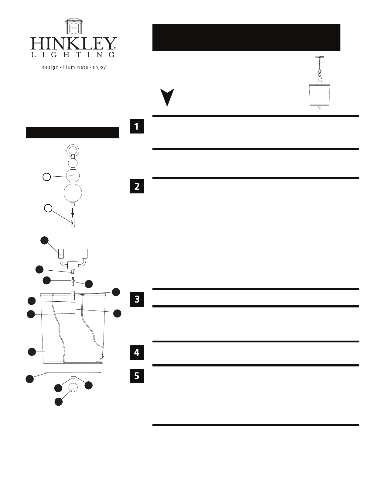
Drawing 1 - Fixture Assembly
T
B
assembly instructions
3449
item No. 3449
start here
1. Find a clear area in which you can work.
2. Unpack fixture and glass from carton.
3. Carefully review instructions prior to assembly.
*** The construction of this fixture will be accomplished by first assembling the
main body of the fixture, installing the mounting bracket, making all necessary
wiring connections, mounting the fiture to the ceiling, and then installing the glass.
1. To assmeble main body of fixture, first slip top column (T) along supply wire and
thread into top center column (B).
2. Next thread hex nut (4) onto end of center stem (3) approximately 3/8” - see
Drawing 1.
3. Thread the center stem (3) into coupler (2), located at the bottom of cluster
assembly (1), approximately 3/8”.
6
8
13
9
1
2
4
3
5
7
shade
tab
11
10
12
4. Tighten hex nut (4) against coupler (2) to sceure center stem (3).
5. Slip tube (5) over center stem (3) followed by cap (6) and hold in position.
6. Slip steel washer (7) followed by rubber washer (8) onto end of center stem (3).
Note: friction from rubber washer should hold parts in postion.
7. Fixture can now be installed. After installation return to these instructions for
glass and shade installation.
Please refer to the hanging instruction sheet (I.S. 19) provided to hang this fixture. Then
refer back to this sheet to install the glass.
SAFETY WARNING: READ WIRING AND GROUNDING INSTRUCTIONS (I.S. 18)
AND ANY ADDITIONAL DIRECTIONS. TURN POWER SUPPLY OFF DURING
INSTALLATION. IF NEW WIRING IS REQUIRED, CONSULT A QUALIFIED
ELECTRICIAN OR LOCAL AUTHORITIES FOR CODE REQUIREMENTS.
Make electrical connections from supply wire to fixture lead wires. Refer to instruction
sheet (I.S. 18) and follow all instructions to make all necessary wiring connections.
1. After fixture body is installed, slip glass (9) onto center stem (3) and hold in
position - see Drawing-1.
2. Slip rubber washer (10) and thread on ring nut (11) onto center stem (3) to secure
glass.
3. Thread thread decorative ball (12) onto center stem (3) and tighten.
4. Slip shade (13) over glass and set tabs inside shade onto top of glass. Center shade
on glass.
HIN K L E Y LIGH T I N G
06.01.13
33000 P in O ak Par kw ay Avo n La ke , Ohio 4 40 12 8 00 -4 46-5 53 9 www.h inkle ylig ht in g.com
Page 2
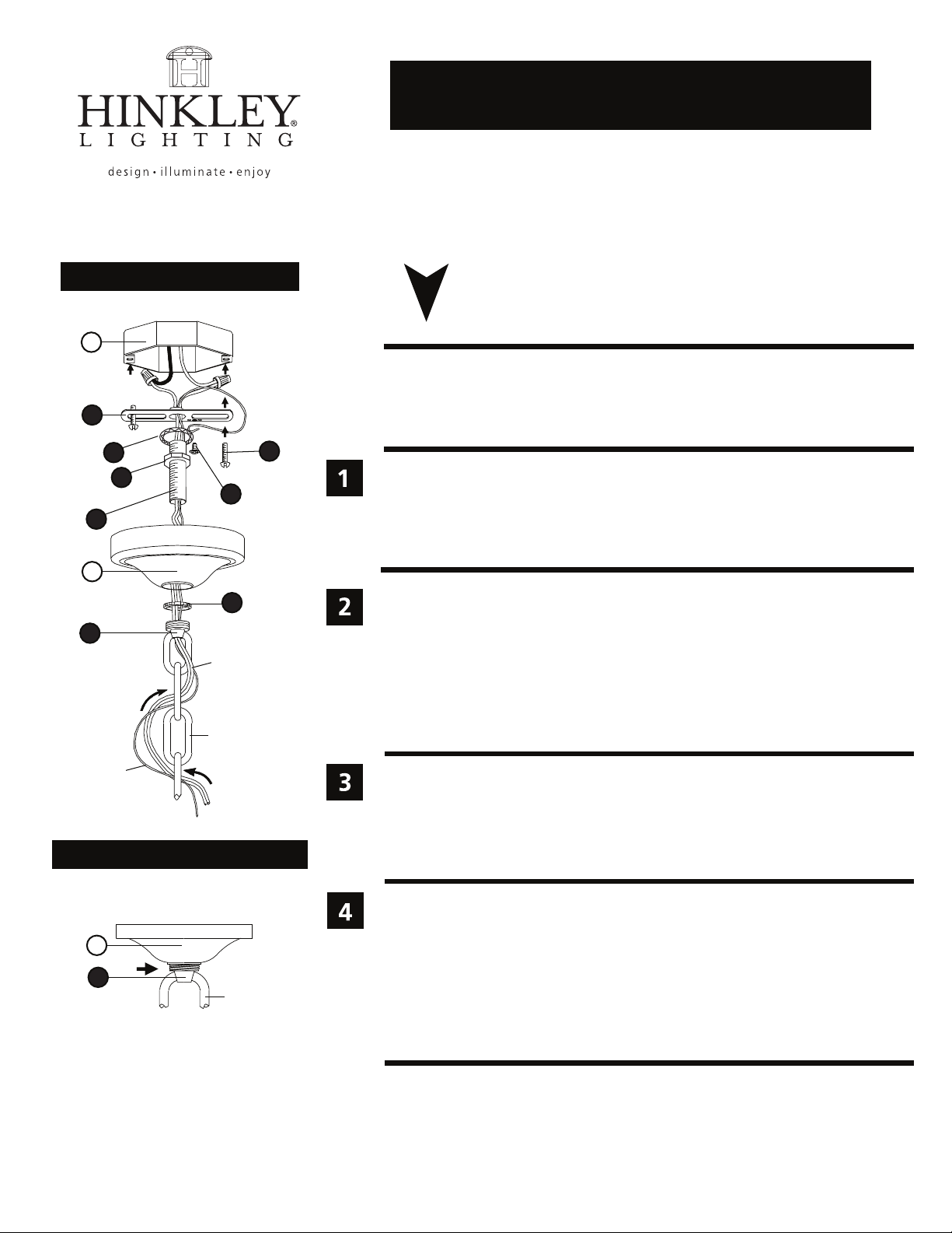
Drawing 1 - Fixture Assembly
A
1
7
8
6
3
I.S.19 hanging instructions
I.S. 19
start here
SAFETY WARNING: READ WIRING AND GROUNDING INSTRUCTIONS (I.S. 18)
AND ANY ADDITIONAL DIRECTIONS. TURN POWER SUPPLY OFF DURING
INSTALLATION. IF NEW WIRING IS REQUIRED, CONSULT A QUALIFIED
ELECTRICIAN OR LOCAL AUTHORITIES FOR CODE REQUIREMENTS.
2
1. Shut off electrical current before starting. If the fixture you are replacing is
turned on and off by a wall switch, simply turn the switch off. If not, remove
the appropriate fuse (or open the circut breakers) until the fixture is dead.
• DO NOT restore current - either by fuse, breaker or switch - until the new
fixture is completely wired and in place.
B
5
4
supply wire
chain
ground wire
Drawing 2 - Loop (4) Detail
Half of thread area of loop (4) is to be exposed.
This will allow collar (5) to be threaded on later.
B
4
chain
1. Fasten mounting strap (1) to outlet box (A) with the original outlet box
screws (2) - see Drawing 1.
2. Slip lockwasher (7) over threaded tube (3) and thread hex nut (8) onto tube (3).
3.Hex nut (8) can be tighened against mounting strap (1) after adjusting thearded
stem (C) to proper mounting length.
4. Thread loop (4) on to end of threaded tube (3).
5. Slip canopy (B) over loop (4) and adjust height of loop so half of thread area
is exposed.
1. Taking the chain, determine the length you require to hang the fixture.
2. Attach one end of the chain to the top loop of the fixture - see Drawing 2.
3. Now slip loop collar (5) and canopy (B) onto chain.
4. Attach other end of chain to loop (4). Get assistance for this step since fixture
may be heavy and difficult to hold while attaching the chain.
1. Unwrap supply wire and ground wire and weave them up through the chain.
2. Slip supply wire and ground wire through center of loop (4).
3. Connect ground wire to mounting strap (1) using green ground screw (6).
4. Make electrical connections from supply wire to fixture lead wires. Refer to
instruction sheet (I.S. 18) and follow all instructions to make all necessary
wiring connections.
5. Slip canopy up firmly against the ceiling and secure by turning the threaded
collar (5) on loop (4) until tight.
HINKLEY LIGHTING 33000 Pin Oak Parkway Avon Lake, OH 44012 800.446.5539 / 440.653.5500 hinkleylighting.com
Page 3
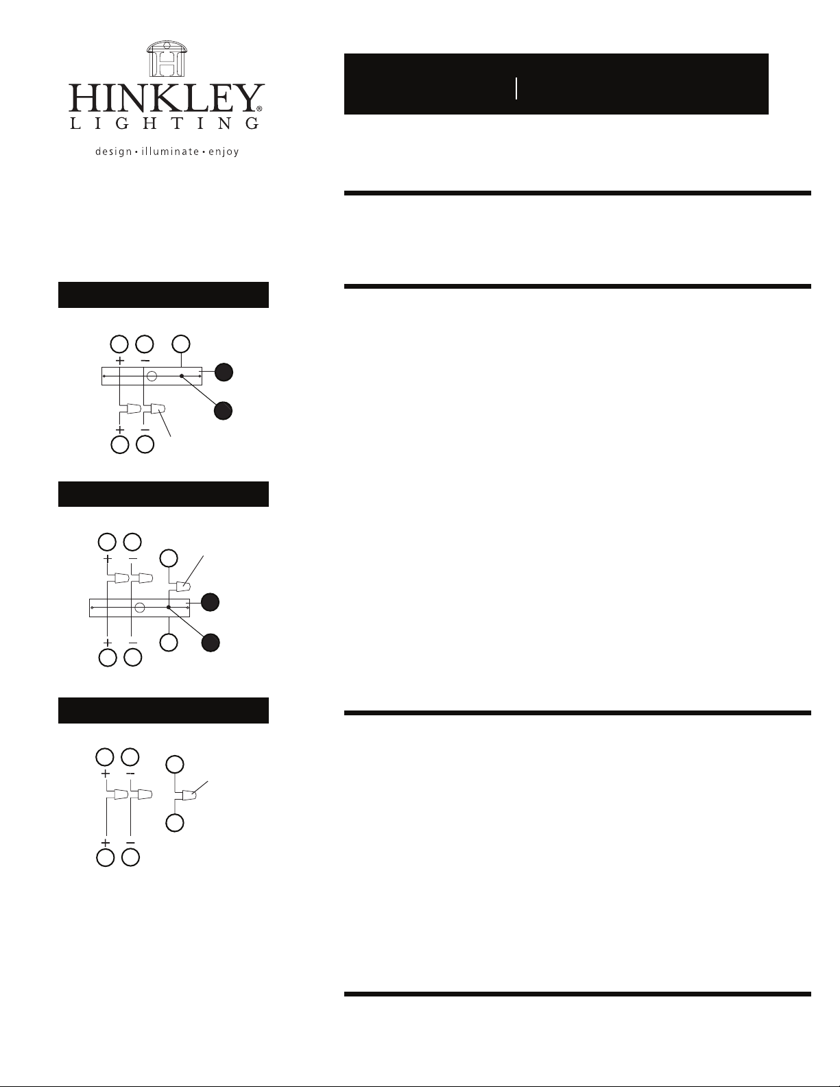
Drawing 1 - Flush Mount
supply wire
A CC
E
I.S. 18 wiring grounding instructions
I.S. 18
SAFETY WARNING: READ WIRING AND GROUNDING INSTRUCTIONS (I.S. 18)
AND ANY ADDITIONAL DIRECTIONS. TURN POWER SUPPLY OFF DURING
INSTALLATION. IF NEW WIRING IS REQUIRED, CONSULT A QUALIFIED
ELECTRICIAN OR LOCAL AUTHORITIES FOR CODE REQUIREMENTS.
wiring instructions
Indoor Fixtures
B
fixture leads
Drawing 2 - Chain Hung
supply wire
connectors
twist-on
D
A C
twist-on
E
E
connectors
1
E
E
D
B
fixture leads
Drawing 3 - Post-Mount
supply wire
A C
2
E
twist-on
connectors
E
D
B
fixture leads
1
2
1. Connect positive supply wire (A) (typically black or the smooth, unmarked
side of the two-conductor cord) to positive fixture lead (B) with appropriately
sized twist on connector - see Drawings 1 or 2.
2. Connect negative supply wire (C) (typically white or the ribbed, marked
side of the two-conductor cord) to negative fixture lead (D).
3. Please refer to the grounding instructions below to complete all
electrical connections.
Outdoor Fixtures
1. Connect positive supply wire (A) (typically black or the smooth unmarked
side of the two-conductor cord) to positive fixture lead (B) with appropriately
sized twist on connector - see Drawings 2 or 3.
2. Connect negative supply wire (C) (typically white or the ribbed, marked
side of the two-conductor cord) to negative fixture lead (D).
3. Cover open end of connectors with silicone sealant to form a watertight seal.
• If installing a wall mount fixture, use caulk to seal gaps between the fixture
mounting plate (backplate) and the wall. This will help prevent water from
entering the outlet box. If the wall surface is lap siding, use caulk and a
fixture mounting platform specially.
4. Please refer to the grounding instructions below to complete all
electrical connections.
grounding instructions
Flush Mount Fixtures
For positive grounding in a 3-wire electrical system, fasten the fixture ground
wire (E) (typically copper or green plastic coated) to the fixture mounting strap (1)
with the ground screw (2) - see Drawing 1.
Note: On straps for screw supported fixtures, first install the two mounting screws in strap.
Any remaining tapped hole may be used for the ground screw.
Chain Hung Fixtures
Loop fixture ground wire (E) (typically copper or green plastic coated) under the
head of the ground screw (2) on fixture mounting strap (1) and connect to the
loose end of the fixture ground wire directly to the ground wire of the building
system with appropriately sized twist-on connectors - see Drawing 2.
Post-Mount Fixtures
Connect fixture ground wire (E) (typically copper or green plastic coated) to power
supply ground with appropriately sized twist-on connector inside post. Cover open
end of connector with silicone sealant to form a watertight seal - see Drawing 3.
HINKLEY LIGHTING 33000 Pin Oak Parkway Avon Lake, OH 44012 800.446.5539 / 440.653.5500 hinkleylighting.com
 Loading...