

Page 1
HINKLEY
L I G H T I N G
Item No. 3277
Assembly Instructions
Les Instructions D’assemblage
english spanish
Número del artículo: 3277
Instrucciones De Montaje
Numéro d’article: 3277
french
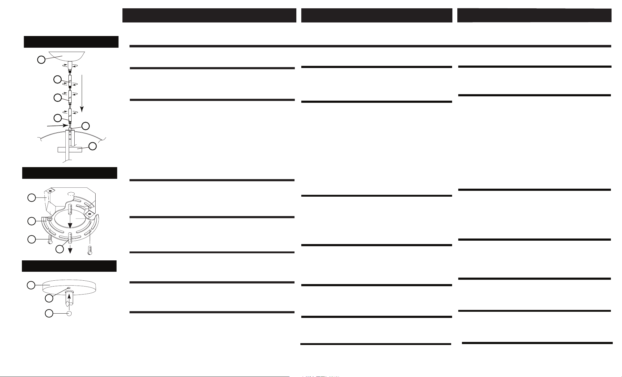
Drawing 1 - Stem Installation
sc
C
C
supply
wire
B
A
1
Drawing 2 - Strap Detail
J
B
G
A
Drawing 3 - Fixture Mounting
D
C
E
1. Find a clear area in which you can work.
2. Unpack fixture and glass from carton.
3. Carefully review instructions prior to assembly.
*** The construction of this fixture will be accomplished by first
determining the length of stem required, mounting the attaching
strap to junction box, making all necessary elctrical connections,
hanging the fixture from the ceiling.
1. Determine the overall length you will need the assembled fixture to
be.
2. Determine what stems will be needed to achieve the overall length
you require. (Additional stems are available and can be ordered.
Ask your local Hinkley Lighting representative or visit
www.hinkleylighting.com for information.)
3. Install first stem (B) by slipping them onto the supply wire of the
fixture, threaded end down, and threading the first stem (B) into
coupling (A) at top of fixture body
4. Install remaining stems (C) by repeating this process until desired
length is met. Then slip supply wire
of the swivel that is attached to the canopy
swivel into the top stem. Fixture is ready for installation.
1. Install screws (A) into mounting plate (B) - see Drawing 2 .
• Be sure the holes into which the screws are threaded match the
spacing of holes
2. Attach mounting plate (B) to junction box (J), using screws (G)
provided and then slip supply wires through large center hole.
SAFETY WARNING: READ WIRING AND GROUNDING
INSTRUCTIONS (I.S. 18) AND ANY ADDITIONAL DIRECTIONS.
TURN POWER SUPPLY OFF DURING INSTALLATION. IF NEW
WIRING IS REQUIRED, CONSULT A QUALIFIED ELECTRICIAN
OR LOCAL AUTHORITIES FOR CODE REQUIREMENTS.
Make electrical connections from supply wire to fixture lead wires.
refer to instruction sheet (I.S. 18)
all necessary wiring connections. Then refer back to this sheet to
continue installation of this fixture.
1. Hang the fixture by slipping screws (A) through hole (C) of canopy
(D) - see Drawing 2 and 3..
2. Thread on ball knobs (E) onto the end of screws (A) and tighten to
secure fixture to ceiling.
CONTINUE ASSEMBLY ON PAGE 2 OF INSTRUCTIONS
start here
.
(C) in the canopy (D) - see Drawings 2 and 3 .
(1) -see Drawing 1
through the center of the
(SC) and thread
and follow all instructions to make
1 . Busque un lugar claro en el que se puede trabajar .
2 . Desembale fixture y el vidrio de la caja.
3 . Revise cuidadosamente las instrucciones antes del montaje .
*** La construcción de este dispositivo se llevará a cabo
determinando primero la longitud del tallo es necesario, el
montaje de la correa de la fijación de la caja de conexiones, por
lo que todas las conexiones eléctricas necesarias , colgando
el aparato del techo,
1 . Determine la longitud total tendrá el accesorio montado ser.
2 . Determinar qué tallos serán necesarios para lograr la longitud
total que usted requiere. (Tallos adicional están disponibles y se
pueden pedir . Pregunte a su representante local de Hinkley
Lighting o visite www.hinkleylighting.com para obtener
información. )
3 . Instale primer vástago (B ) por el deslizamiento de ellos en el
cable de alimentación de la luminaria , extremo roscado hacia
abajo, y enhebrar el primer vástago (B ) en el acoplamiento ( A)
en la parte superior del cuerpo de la luminaria ( 1 )
- ver Drawin.g 1
4 . Instale restante tallos (C ) , repitiendo este proceso hasta que
se cumpla la longitud deseada. Entonces deslizarse cable de
suministro a través del centro de la de la pieza giratoria que está
unida a la cubierta ( SC ) y giro de rosca en el vástago de la parte
superior . Fixture está listo para la instalación.
1 . Instale los tornillos ( A ) en la placa de montaje ( B)
- ver dibujo 2 .
• Asegúrese de que los agujeros en los que se enroscan los
tornillos coinciden con el espaciamiento de los orificios (C )
en el dosel (D) - ver dibujos 2 y 3.
2 . Fije la placa de montaje ( B) a la caja de conexiones ( J) , con
los tornillos (G ), siempre y luego deslizarse cables de
alimentación a través del agujero central grande .
ADVERTENCIA DE SEGURIDAD : LEA INSTRUCCIONES DE
CABLEADO (IS 18 ) , E INSTRUCCIONES ADICIONALES. APAGUE
LA FUENTE DE ALIMENTACIÓN DURANTE LA INSTALACIÓN. SI
NUEVO CABLEADO SE REQUIERE , CONSULTE A UN TÉCNICO
CALIFICADO AUTORIDADES DE ELECTRICISTA O LOCALES PARA
REQUISITOS DEL CÓDIGO .
Haga las conexiones eléctricas del cable de alimentación al
accesorio cables conductores. Consulte la hoja de instrucciones
(IS 18 ) y siga todas las instrucciones para hacer todas las
conexiones necesarias . Entonces referirse a esta hoja para
continuar con la instalación de este accesorio.
1. Cuelgue el aparato por medio de tornillos de deslizamiento (A) a través del
agujero (C) de la copa (D) - vea el dibujo 2 y 3.
2. Tema de las perillas de bolas (E) en el extremo de los tornillos (A) y
apriete a asegure luminaria al techo.
empezar aquí
commencez ici
1. Allez dans un endroit dans lequel vous pouvez travailler .
2 . Déballez luminaire et le verre de carton .
3 . Lire attentivement les instructions avant l'assemblage .
*** La construction de cet accessoire sera accomplie en déterminant
d'abord la longueur de tige nécessaire , le montage de la courroie de
fixation à la boîte de jonction , tous les raccordements électriques
nécessaires , accrocher le projecteur du plafond,
1 . Déterminer la longueur totale , vous devrez l'appareil assemblé
être .
2 . Déterminer ce qui relève sera nécessaire pour atteindre la
longueur totale dont vous avez besoin . ( Tiges supplémentaires sont
disponibles et peuvent être commandés . Demandez à votre
représentant Hinkley Lighting locale ou visitez www.hinkleylighting
.com pour plus d'informations . )
d'alimentation de l'appareil , l'extrémité filetée vers le bas, et le
filetage de la première tige ( B ) dans le raccord ( A) en haut du corps
de fixation ( 1 ) - voir Drawin.g 1
4 . Installez tiges résiduelles ( C ) en répétant ce processus jusqu'à
ce que la longueur désirée est atteint . Ensuite, faites glisser le fil
d'alimentation à travers le centre de la de la rotule qui est attaché à
la canopée ( SC ) et du fil pivotant dans la tige supérieure . Luminaire
est prêt pour l'installation .
1 . Installez les vis ( A ) dans la plaque de montage ( B )
- voir schéma 2 .
• Assurez-vous que les trous dans lesquels les vis sont vissées
correspondent l'espacement des trous ( C ) dans la canopée ( D )
- voir dessins 2 et 3 .
2 . Fixez la plaque de montage (B ) à la boîte de jonction (J ) , en
utilisant les vis ( G ) fourni, puis glisser fils d'alimentation à travers
le trou de grand centre .
AVERTISSEMENT DE SÉCURITÉ : LIRE RACCORDEMENT ET MISE À LA
TERRE (IS 18) ET TOUTE AUTRE INSTRUCTION . COUPER
L'ALIMENTATION ÉLECTRIQUE PENDANT L'INSTALLATION. SI DE
NOUVELLES CÂBLAGE N'EST NÉCESSAIRE , CONSULTER UN
SPÉCIALISTE QUALIFIÉ AUTORITÉS LOCALES POUR ÉLECTRICIEN OU
EXIGENCES DU CODE.
Effectuer les connexions électriques du câble d'alimentation au
montage des fils conducteurs . Reportez-vous à la feuille d'instruction
(IS 18 ) et suivez les instructions pour faire tous les raccordements
nécessaires . Ensuite, se reporter à la fiche de poursuivre l'installation
de cet accessoire .
Une. Accrochez l'appareil par des vis de glissement (A) dans le trou (C) de la
canopée (D) - voir schéma 2 et 3.
2. Discussion sur les poignées de billes (E) sur l'extrémité de vis (A) et serrer à
Fixez luminaire au plafond.
lfi el rus tnassilg sel ne ) B ( egit erèimerp al rellatsnI . 3
CONTINUAR LA ASAMBLEA EN LA PÁGINA 2 DE INSTRUCCIONES
CONTINUER ENSEMBLE EN PAGE 2 DE MODE
PAGE 1
Page 2
HINKLEY
LIGHTING
Item No. 3277
Assembly Instructions
Instrucciones De Montaje
english spanish
Número del artículo: 3277
Les Instructions D’assemblage
Numéro d’article: 3277
french
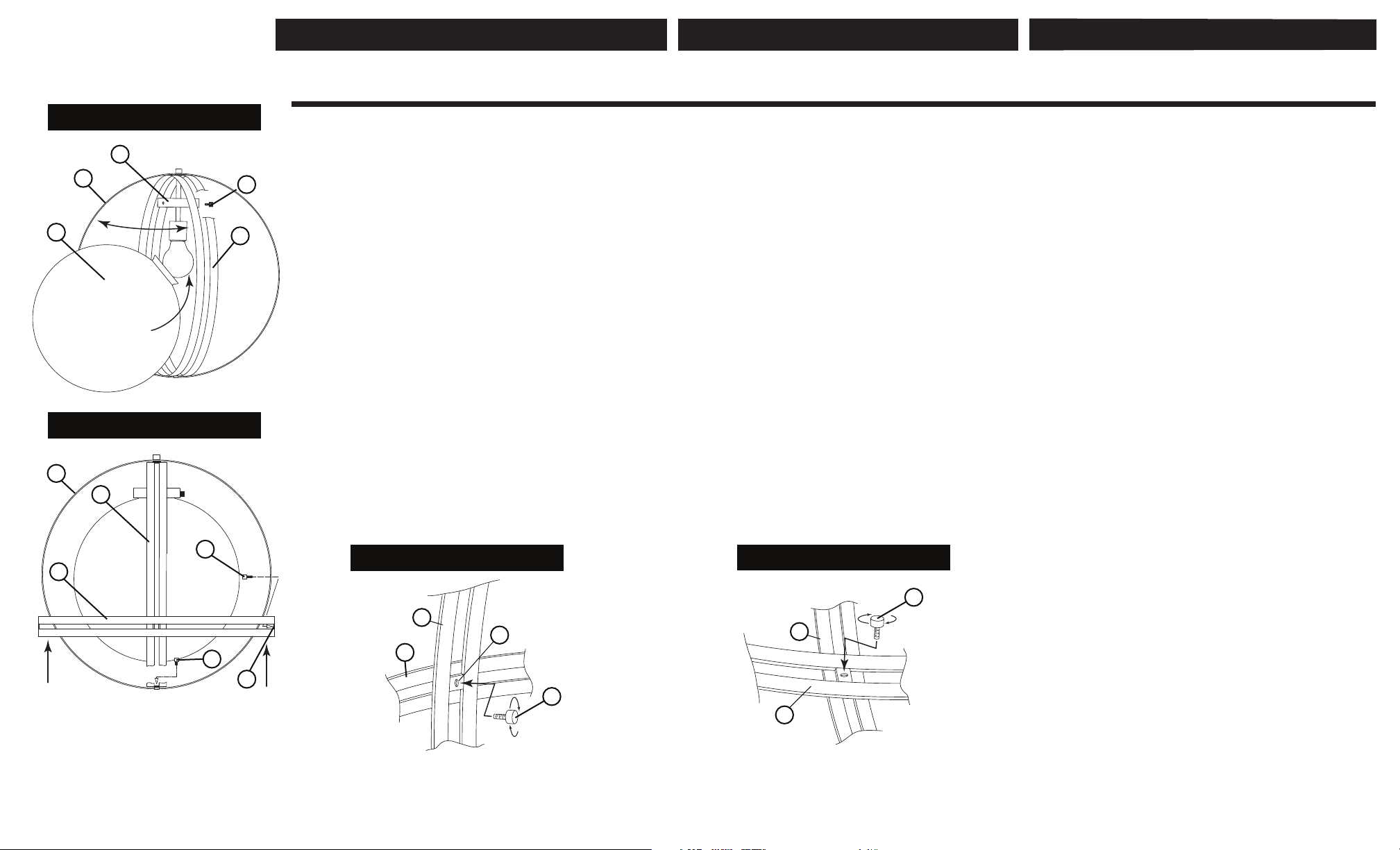
Drawing 1 - glass installation
GR
VR
GG
Drawing 1 - ring installation
VR
VR
VR
RS
1. Lamp the fixture accordingly prior to installing the glass.
2. To install glass gently separate and hold the vertical rings (VR) until the
glass globe (GG) can be easily slipped between the rings -see Drawing 1.
3. Slip the top of the glass globe over lamp and socket and into glass
retainer (GR). Thread in retainer screws (RS) to secure glass in fixture.
4. Move vertical rings (VR) back to original position.
1. To complete assembly of this fixture, carefully slip horizontal ring (HR)
over outside of vertical rings (VR) of fixture - see Drawing 1.
2. Align the holes (VH) in the vertical ring with the holes (HH) located on
at the mid line of the horizontal ring (HR) - see Drawing 1 and Detail
drawing 1.
3. Now while holding ring (VR) in position, slip barrel knob with studs (BK)
through hole (VH) in vertical ring (VR), and thread stud into threaded hole
(HH) of horizontal ring, and tighten to secure.
4. To complete assembly align holes at the bottom of vertical rings (VR) and
thread in barrel knob with stud (BK) to secure vertical rings (VR) see
Drawing 2 and Detail drawing 2.
5. Fixture is complete and can be lamped accordingly.
start here
empezar aquí
1 . Lámpara del accesorio en consecuencia antes de instalar el vidrio.
2 . Para instalar el vidrio separar suavemente y mantenga los anillos verticales
(VR) hasta que el globo de cristal (GG ) puede deslizarse fácilmente entre los
anillos - ver dibujo 1 .
3 . Deslice la parte superior del globo de cristal sobre la lámpara y el enchufe
y en el retén de vidrio ( GR) . Enrosque los tornillos de retención (RS) para
asegurar el vidrio en la luminaria .
4 . Mueva los anillos verticales (VR) de nuevo a su posición original.
1 . Para completar el montaje de este aparato, deslice con cuidado el anillo
horizontal ( HR ) sobre el exterior de los anillos verticales ( VR ) de jación
- ver dibujo 1 .
2 . Alinee los oricios (VH) en el anillo vertical con los oricios ( HH ) ubicados
en en la línea media del anillo horizontal (HR ) - ver dibujo 1
y Detalle dibujo 1.
3 . Ahora mientras que la celebración de anillo (VR ) en posición, perilla barril
deslizamiento con espárragos ( BK) a través del agujero (VH ) en el anillo
vertical ( VR) , y el perno de rosca en el oricio roscado (HH ) de anillo
horizontal , y apriete para asegurar.
4 . Para completar el montaje alinear los agujeros en la parte inferior de los
anillos verticales (VR ) y enrosque la perilla de cañón con espárrago ( BK )
para jar los anillos verticales (VR ) ver dibujo 2 y Detalle dibujo 2 .
5 . Aparato está completa y se puede lamped en consecuencia.
commencez ici
1. Lampe l'appareil en conséquence avant d'installer le verre .
2 . Pour installer verre délicatement séparer et maintenir les anneaux verticaux
(VR) jusqu'à ce que le globe de verre (GG ) peut être facilement glissé entre les
anneaux - voir schéma 1 .
3 . Glissez le sommet du globe de verre sur la lampe et la douille et en verre de
retenue ( GR ) . Enlez les vis de retenue ( RS) pour garantir verre luminaire.
4 . Déplacez anneaux verticaux (VR) à sa position initiale .
Une . Pour terminer l'assemblage de ce luminaire , glisser soigneusement
anneau horizontal ( HR ) sur l'extérieur d'anneaux verticaux ( VR ) de xation
- voir schéma 1 .
2 . Alignez les trous (VH) dans l'anneau vertical avec les trous ( HH ) situés sur
la ligne médiane de l' anneau horizontal (HR ) - voir schéma 1 et
le dessin Détail 1 .
3 . Or, tandis que la bague de maintien ( VR ) en position , glisser le bouton
de canon avec des clous (BK) dans le trou ( VH ) dans l'anneau vertical ( VR ) ,
et le l goujon dans le trou leté (HH ) de l'anneau horizontal , et serrer.
4 . Pour terminer l'assemblage aligner les trous au fond d'anneaux verticaux
( VR ) et du l à bouton de canon avec le goujon ( BK ) pour xer les anneaux
verticaux (VR ) voir schéma 2 et dessin de détail 2 .
5 . Luminaire est complet et peut être lamped conséquence.
HR
BK
BK
HH
Detail drawing 1
VR
HR
VH
Detail drawing 2
BK
VR
BK
VR
PAGE 2
Page 3

Drawing 1 – Flush Mount
Drawing 2 – Chain Hung
Drawing 3 – Post-Mount
I.S. 18
wiring grounding instructions
SAFETY WARNING: READ WIRING AND GROUNDING
INSTRUCTIONS (IS 18) AND ANY ADDITIONAL DIRECTIONS.
TURN POWER SUPPLY OFF DURING INSTALLATION. IF NEW
WIRING IS REQUIRED, CONSULT A QUALIFIED ELECTRICIAN OR
LOCAL AUTHORITIES FOR CODE REQUIREMENTS
I.S. 18
câblage échouage instructions
AVERTISSEMENT DE SECURITE: LIRE CABLAGE ET INSTRUCTIONS DE
MISE (IS 18), ET TOUTE AUTRE INSTRUCTION. COUPER L’ALIMENTATION
ELECTRIQUE PENDANT L’ONSTALLATION. SI DE NOUVELLES CABLAGE
N’EST NECESSAIRE, CONSULTEZ UN ELECTRICIEN QUALIFIE OU
AUTORITES LOCALES POUR EXIGENCES DU CODE.
wiring instructions
Indoor Fixtures
1. Connect positive supply wire (A) (typically black or the smooth,
unmarked side of the two-conductor cord) to positive fixture lead (B)
with appropriately sized twist on connector - see Drawings 1 or 2.
2. Connect negative supply wire (C) (typically white or the ribbed, marked
side of the two-conductor cord) to negative fixture lead (D).
3. Please refer to the grounding instructions below to complete all
electrical connections
Outdoor Fixtures
1. Connect positive supply wire (A) (typically black or the smooth
unmarked side of the two-conductor cord) to positive fixture lead (B)
with appropriately sized twist on connector --- see Drawings 2 or 3.
2. Connect negative supply wire (C) (typically white or the ribbed, marked
side of the two-conductor cord) to negative fixture lead (D).
3. Cover open end of connectors with silicone sealant to form a
watertight seal.
If installing a wall mount fixture, use caulk to seal gaps between the
fixture mounting plate (backplate) and the wall. This will help prevent
water from entering the outlet box. If the wall surface is lap siding, use
caulk and a fixture mounting platform specially.
4. Please refer to the grounding instructions below to complete all
electrical connections.
instructions de câblage
Luminaires Itérieurs
1. Brancher le fil d’alimentation positive (A) (généralement noir ou, côté lisse
banalisée de la corde á deux conducteurs) á plob de fixation positive (B) avec
la torsion de taille appropriée sur le connecteur --- Voir Schéma 1 ou 2.
2. Connecter le fil d’alimentation négative (C) (généralement blanc ou l’, côté
marqué nervurée du fil á deux conducteurs) au conducteur négatif de
l’appareil (D).
3. S’il vous plaît se référer á la mise á la terre instructions ci-dessous pour
terminer toutes les connexions électriques.
Luminaires Extérieurs
1. Brancher le fil d’alimentation positive (A) (généralement noir ou le côté lisse
banalisée de la corde á deux conducteurs) á plomb de fixation positive (B)
avec la torsion approrpriately taille du connecteur --- Voir Schéma 2 ou 3.
2. Connecter le fil d’alimentation négative (C) (généralement blanc ou l’, côté
marqué nervurée du fil á deux conducteurs) au conducteur négatif de
l’appareild (D).
3. Couvrir extrémité ouverte de connecteurs acex du silicone pour former un
joint étenche á l’eau.
Si l’installation d’un luminaire de montage mural, utiliser calfeutrage pour
sceller l’espace entre la plaque de montage de fixation (plaque arriére) et la
paroi. Cela aidera á empêcher l’eau de pénétrer dans le boc sortie. Si la
surface du mur est bardage á clin, utiliser caldeutrage et une plate-forme de
montage d’appareils spécialement.
4. S’il vous plait se referrer auc instructions ci-dessous pour terminer la terre
toutes les connexions électrques.
grounding instructions
Flush Mount Fixtures
For positive grounding in a 3-wire electrical system, fasten the fixture
ground wire (E) (typically copper or green plastic coated) to the fixture
mounting strap (M) with the ground screw (S) - see Drawing 1.
Note: On straps for screw supported fixtures, first install the two mounting
screws in strap. Any remaining tapped hole may be used for the ground screw.
Chain Hung Fixtures
Loop fixture ground wire (E) (typically copper or green plastic coated)
under the head of the ground screw (S) on fixture mounting strap (M)
and connect to the loose end of the fixture ground wire directly to the
ground wire of the building system with appropriately sized twist-on
connectors - see Drawing 2.
Post-Mount Fixtures
Connect fixture ground wire (E) (typically copper or green plastic coated)
to power supply ground with appropriately sized twist-on connector
inside post. Cover open end of connector with silicone sealant to form a
watertight seal - see Drawing 3.
instructions de mise
Montage Encastré Fixtures
Pour la terre positive dans un systéme électrique á 3 fils, fixez le fil de terre du
luminaire (E) (généralement en cuivre ou vert recouvert de plastique) á la sangle
de fixation de fixation (M) avec la vis de terre (S) --- Voir Schéma 1.
Remarque: Sur les sangles pour les appareils pris en charge á vis, installez d’abord les
deux vis de fixation á sangle. Tout trou taraudé restante peut être utilisée pour la vis de
terre.
Chaîne Accroché Luminaires
Boucle fil du luminaire au sol (E) (généralement en cuivre ou vert recouvert de
plastique) sous la tête de la vis de terre (S) sur la sangle de fixation de fixation
(M) et se connecter á l’extrémitré libre du fil de terre du luminaire directement
sur le fil de terre du systéme de construction avec une taille appropriée
connecteurs á visser --- Voir Schéma 2.
Luminaires Aprés Montage
Brancher le fil de terre du luminaire (E) (généralement en cuivre ou vert
recouvert de plastique) á la masse de l’alimentation avec une taille appropriée
torsion sur le connecteur á l’intérieur de la poste. Couvrir extrémité ouverte du
connecteur avec du mastic silicone pour former un joint étache á l’eau --- Voir
Schéma 3.
I.S. 18 tierra cableado instrucciones
ADVERTENCIA DE SEGURIDAD: LEA LAS INSTRUCCIONES DE CABLEADO
Y LA TIERRA (IS 18), E INSTRUCCIONES ADICIONALES. APAUGE LA
ALIMENTACIÓN DE CORRIENTE DURANTE LA INSTALACIÓN. SI SE
REQUIERE NUEVO CABLEADO, CONSULTE CON UN ELECTRICISTA O
AUTHORIDADES LOCALES PARA REQUISITOS DEL CÓDIGO
Instrucciones de cableado
Acesorios Cubierta
1. Conecte el cable de alimentación positive (A) (normalmente negro o la cara
lisa, sin marcas del cable de dos conductores) de plomo accesorio positivo (B)
con un giro de tamaño adecuado en el conector --- Véase la Figura 1 y 2.
2. Conecte el cable de alimentación negativa (C) (por lo general de color
blanco o el lado marcado estriado del cable de dos conductores) de plomo
accesorio negativo (D).
3. Por favor, consulte las instrucciones de puesta a tierra-a continuación para
completar todas las conexiones eléctricas.
Accesorios Exterior
1. Conecte el cable de alimentación positiva (A) (normalmente negro el lado no
marcado suave del cable de dos conductores) de plomo accesorio positivo (B)
con un giro de tamaño approrpriately conector --- Véase la Figura 2 y 3.
2. Conecte el cable de alimentación negative (C) (por lo general de color
blanco o el lado marcado estriado del cable de dos conductores) de plomo
accesorio negativo (D).
3. Cubra el extreme abierto de conectores con sellador de silicona poara formar
un sello hermético.
Si va a instalar un soporte de fijación mural, use masilla para sella los
espacios entre la placa de montaje del aparato (placa) y la pared. Esto
ayudará a evitar que el agua entre en la boc salida. Si la superficie de la
pared es de revestimiento solapado, utilice masilla y una plataforma de
montaje accesorio especial.
4. Por favor, consulte las Instrucciones de puesta a tierra-a continuación para
completar todas las conexiones eléctricas.
instrucciones puesta a tierra
Montaje Embutido Accesorios
Para conectar a tierra en un sistema eléctrico de 3 hilos, fije el cable de tierra
del artefacto (E) (generalmente de cobre o verde recubierto de plástico) a la
brida de montaje accesorio (M) con el tornillo de tierra (S) --- Véase la Figura 1.
Nota : En las correas de accesorios compatibles tornillos, primero instale los dos
tornillos de montaje de la correa. Cualquier agujero roscado restante puede ser
utilizado para el tornillo de tierra.
Cadena Hung Accesorios
Loop alambre de tierra (E) (generalmente de cobre o verde recubierto de
plático) debajo de la cabeza del tornillo de tierra (S) en la brida de montaje
accesorio (M) y conectar con el extremo suelto del cable de tierra luminaria
directamente al cable de tierra del sistema de construcción con un tamaño
adecuado twist-conectores --- Véase la Figura 2.
Accesorios Posterior Monte
Conecte el cable de tierra del artefacto (E) (generalmente de cobre o verde
recubierto de plástico) a tierra de la fuente de alimentacón con conector de
tamanño adecuado en el interior puesto enlaces en forma. Cubra el extremo
abierto del conector con sellador de silicona para formar un sello hermético --Véase la Figura 3.
H I N K L E Y L I G H T I N G 33000 Pin Oak Parkway Avon Lake, OH 44012 800.446.5539 / 440.653.5500 hinkleylighting.com
 Loading...