

Page 1
assembly instructions
H I N K L E Y L I G H T I N G 33000 Pin Oak Parkway Avon Lake, OH 44012 800.446.5539 / 440.653.5500 hinkleylighting.com
Family: Hampton Item No. 3214
3214
Drawing 1 - Fixtu
re Assembly
A
Drawing 2 - Fixture Assembly
A
2
7
3
start here
1. Find a clear area in which you can work.
2. Unpack fixture and glass from carton.
3. Carefully review instructions prior to assembly.
*** The construction of this fixture will be accomplished by first assembling the
main body structure, installing the mounting hardware to the junction box, hanging
the fixture from the ceiling, and then completing the fixture assembly.
SAFETY WARNING: READ WIRING AND GROUNDING INSTRUCTIONS (I.S. 18)
AND ANY ADDITIONAL DIRECTIONS. TURN POWER SUPPLY OFF DURING
INSTALLATION. IF NEW WIRING IS REQUIRED, CONSULT A QUALIFIED
ELECTRICIAN OR LOCAL AUTHORITIES FOR CODE REQUIREMENTS.
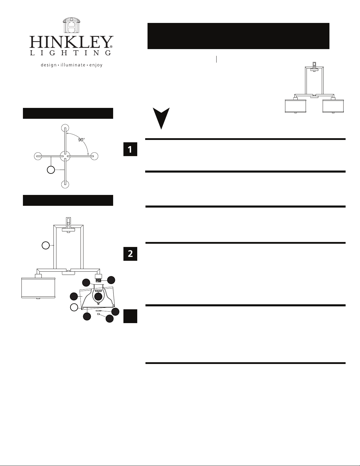
1. Rotate the three uprights (A) until they are approximately 90 degrees apart - see
Drawing 1.
2. To attach shades first remove socket ring (3) from socket (1) - see Drawing 2.
1
3. Slip shade harp (2) over socket and hold in position.
4. Thread socket ring (3) back onto socket to secure shade harp (2).
5. Fixture can be installed at this time please refer to mounting instructions (IS-19)
provided with this fixture. Then refer back to this sheet to finish installation.
B
4
5
6
3
1. Attach acrylic lens (4) to harp by slipping center hole over threaded tube on harp
followed by cap (5) - see Drawing 2.
2. Hold both lens and cap in position and thread on knob (6) and tighten to secure
parts.
3. It is recommended that the fixture be lamped accordingly at this time.
4. Take shade (7) and manuver shade over acrylic lens so tabs (B) rest on the top side
of the lens. Center shade on lens and assembly is complete.
10.26.10
Page 2
Drawing 1 - Flush Mount
H I N K L E Y L I G H T I N G 33000 Pin Oak Parkway Avon Lake, OH 44012 800.446.5539 / 440.653.5500 hinkleylighting.com
supply wire
A CC
E
I.S. 18 wiring grounding instructions
I.S. 18
SAFETY WARNING: READ WIRING AND GROUNDING INSTRUCTIONS (I.S. 18)
AND ANY ADDITIONAL DIRECTIONS. TURN POWER SUPPLY OFF DURING
INSTALLATION. IF NEW WIRING IS REQUIRED, CONSULT A QUALIFIED
ELECTRICIAN OR LOCAL AUTHORITIES FOR CODE REQUIREMENTS.
wiring instructions
Indoor Fixtures
B
fixture leads
Drawing 2 - Chain Hung
supply wire
connectors
twist-on
D
A C
twist-on
E
E
connectors
1
E
E
D
B
fixture leads
Drawing 3 - Post-Mount
supply wire
A C
2
E
twist-on
connectors
E
D
B
fixture leads
1
2
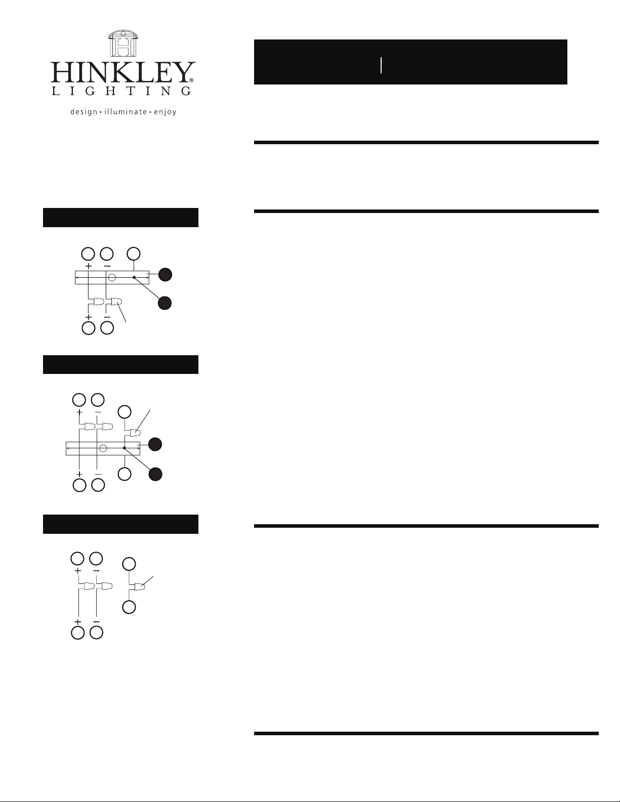
1. Connect positive supply wire (A) (typically black or the smooth, unmarked
side of the two-conductor cord) to positive fixture lead (B) with appropriately
sized twist on connector - see Drawings 1 or 2.
2. Connect negative supply wire (C) (typically white or the ribbed, marked
side of the two-conductor cord) to negative fixture lead (D).
3. Please refer to the grounding instructions below to complete all
electrical connections.
Outdoor Fixtures
1. Connect positive supply wire (A) (typically black or the smooth unmarked
side of the two-conductor cord) to positive fixture lead (B) with appropriately
sized twist on connector - see Drawings 2 or 3.
2. Connect negative supply wire (C) (typically white or the ribbed, marked
side of the two-conductor cord) to negative fixture lead (D).
3. Cover open end of connectors with silicone sealant to form a watertight seal.
• If installing a wall mount fixture, use caulk to seal gaps between the fixture
mounting plate (backplate) and the wall. This will help prevent water from
entering the outlet box. If the wall surface is lap siding, use caulk and a
fixture mounting platform specially.
4. Please refer to the grounding instructions below to complete all
electrical connections.
grounding instructions
Flush Mount Fixtures
For positive grounding in a 3-wire electrical system, fasten the fixture ground
wire (E) (typically copper or green plastic coated) to the fixture mounting strap (1)
with the ground screw (2) - see Drawing 1.
Note: On straps for screw supported fixtures, first install the two mounting screws in strap.
Any remaining tapped hole may be used for the ground screw.
Chain Hung Fixtures
Loop fixture ground wire (E) (typically copper or green plastic coated) under the
head of the ground screw (2) on fixture mounting strap (1) and connect to the
loose end of the fixture ground wire directly to the ground wire of the building
system with appropriately sized twist-on connectors - see Drawing 2.
Post-Mount Fixtures
Connect fixture ground wire (E) (typically copper or green plastic coated) to power
supply ground with appropriately sized twist-on connector inside post. Cover open
end of connector with silicone sealant to form a watertight seal - see Drawing 3.
 Loading...