

Page 1
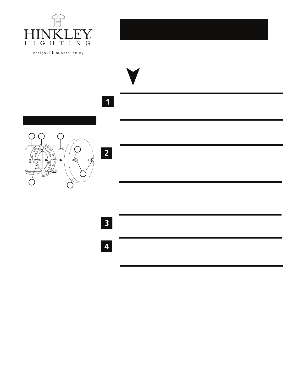
Drawing 1 - Fixture Mounting
J
CA
assembly instructions
start here
1. Find a clear area in which you can work.
2. Unpack fixture and glass from carton.
3. Carefully review instructions prior to assembly.
*** The construction of this fixture will be accomplished by first mounting the
mounting strap to the junction box, making all necessary electrical connections,
mounting the fixture to the wall and then installing the glass.
D
F
B
E
1. Prepare mounting strap (A) by threading the two 1 1/4” long mounting screws (B)
into the back of the universal strap - see Drawing 1.
• Be sure the holes into which the screws are threaded match the spacing of holes (D)
in the back plate (E).
2. Attach mounting strap (A) to junction box (J) using two 1” screws (C) provided.
SAFETY WARNING: READ WIRING AND GROUNDING INSTRUCTIONS (I.S. 18)
AND ANY ADDITIONAL DIRECTIONS. TURN POWER SUPPLY OFF DURING
INSTALLATION. IF NEW WIRING IS REQUIRED, CONSULT A QUALIFIED
ELECTRICIAN OR LOCAL AUTHORITIES FOR CODE REQUIREMENTS.
Make electrical connections from supply wire to fixture lead wires. Refer to instruction
sheet (I.S. 18) and follow all instructions to make all necessary wiring connections.
Then refer back to this sheet to continue installation of this fixture.
1. To mount fixture, slip the two mounting screws (B) through the two mounting holes
(D) in the backplate (E) - see Drawing 1.
2. While holding fixture in place, thread the two ball knobs (F) on to the end
of the mounting screws (B), and tighten.
H I N K L E Y L I GHT I N G 33000 Pin Oak Park w a y Avon L a k e , OH 4 4 0 1 2 8 0 0 . 4 4 6 . 5 5 3 9 / 4 4 . 6 53. 5 5 0 0 hinkleylightin g .co m
 Loading...