

Page 1
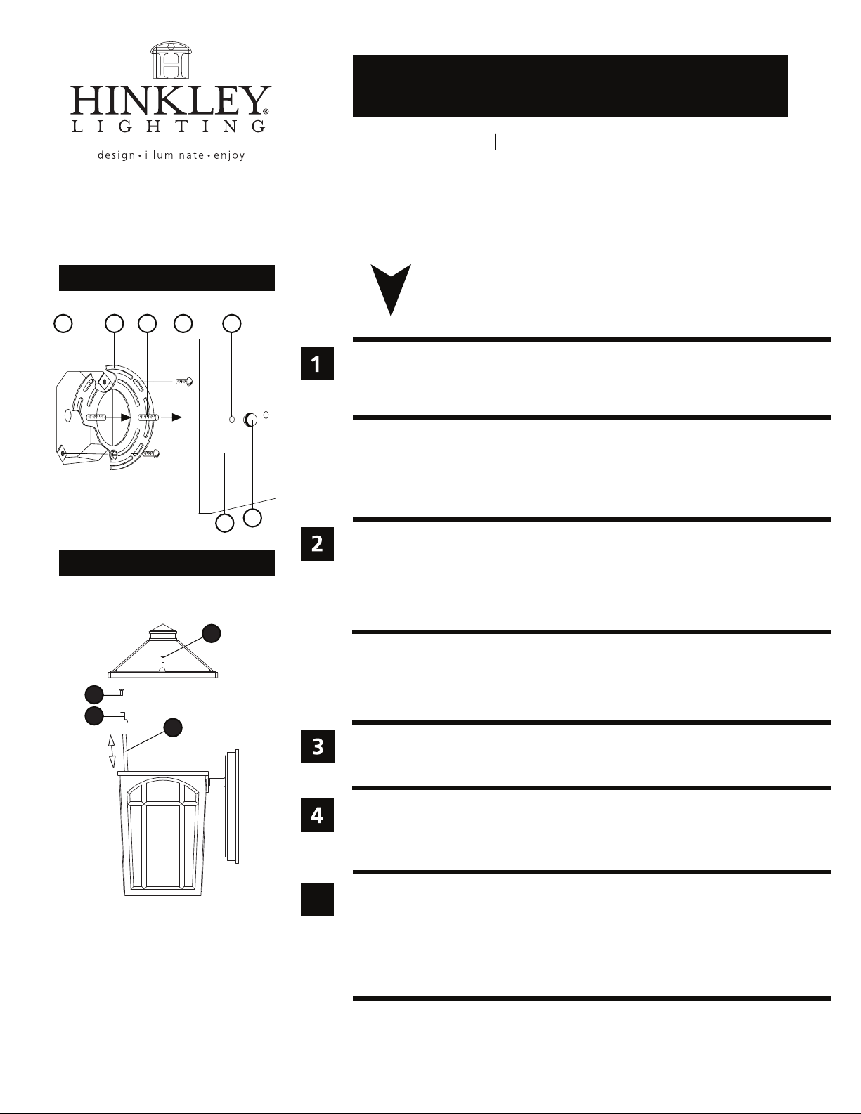
Drawing 1 - Fixture Mounting
assembly instructions
Item No. 1980 / 1984
1984
1980
J
A
B C D
Drawing 2 - Glass Installation
4
5
6
start here
1. Find a clear area in which you can work.
2. Unpack xture and glass from carton.
3. Carefully review instructions prior to assembly.
*** The construction of this xture will be accomplished by rst mounting the
mounting strap to the junction box, making all necessary electrical connections,
mounting the xture to the wall, and then lamping the xture.
F
E
3
1. Prepare mounting strap (A) by threading the two 1 1/4” long mounting screws (B)
into the back of the mounting strap (A) - see Drawing 1.
• Be sure the holes into which the screws are threaded match the spacing of holes (D)
in the backplate (E).
2. Attach mounting strap (A) to junction box (J) using two 1” screws (C).
SAFETY WARNING: READ WIRING AND GROUNDING INSTRUCTIONS (I.S. 18)
AND ANY ADDITIONAL DIRECTIONS. TURN POWER SUPPLY OFF DURING
INSTALLATION. IF NEW WIRING IS REQUIRED, CONSULT A QUALIFIED
ELECTRICIAN OR LOCAL AUTHORITIES FOR CODE REQUIREMENTS.
Make electrical connections from supply wire to xture lead wires. Refer to instruction sheet (I.S.
18) and follow all instructions to make all necessary wiring connections. Then refer back to this
sheet to continue installation of this xture.
1. To mount xture, slip the two mounting screws (B) through the two mounting holes (D) in the
backplate (E) - see Drawing 1.
2. While holding xture in place, thread the two ball knobs (F) on to the end of the mounting
screws (B), and tighten.
5
HINKLEY LIGHTING 12600 Berea Road Cleveland, OH 44111 800.446.5539 / 216.671.3300 www.hinkleylighting.com
Glass Installation Instructions - see Drawing 3.
1. Remove the at head phillips screws (3) located on the top of the xture and remove roof.
2. Remove the securing screw (4) from glass clips (5).
3. Pull up on glass panel (6) and remove.
4. To replace the glass follow steps 1-2 in reverse order.
6.1.12
 Loading...