

Page 1
assembly instructions
Item No. 1891 / 1921
1891
1921
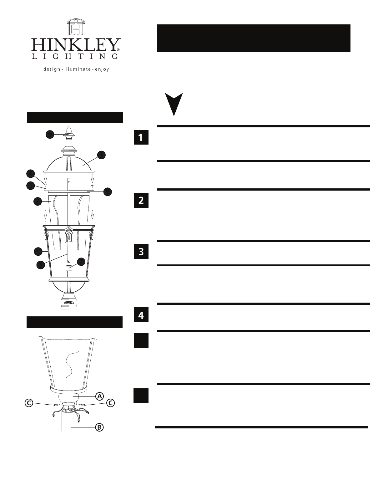
Drawing 1 - Fixture Assembly
9
4
5
2
1
6
7
start here
1. Find a clear area in which you can work.
2. Unpack fixture and glass from carton.
8
3
3. Carefully review instructions prior to assembly.
*** The construction of this fixture will be accomplished by first assembling
main body of the fixture, making all necessary electrical connections, and then
mounting the fixture to pre-installed post.
1. To install glass (2), remove retainer ring (3) from cage assembly (1) by removing
the four screws (4) and lockwasher (5) - see Drawing 1.
2. Lift retainer ring (3) off of studs (S).
3. Slip glass (2) into cage assembly (1), replace retainer ring (3) and replace lockwashers
(5) and thread screws (4) onto studs (S) and tighten to secure glass.
4. Thread center stem (6) into top of cluster assembly (7).
5. Fixture can be installed at this time.
1. Fixture is mounted using 3 - 1/4-20 set screws.
2. Make all necessary electrical connections following wiring instructions below.
SAFETY WARNING: READ WIRING AND GROUNDING INSTRUCTIONS (I.S. 18)
AND ANY ADDITIONAL DIRECTIONS. TURN POWER SUPPLY OFF DURING
INSTALLATION. IF NEW WIRING IS REQUIRED, CONSULT A QUALIFIED
ELECTRICIAN OR LOCAL AUTHORITIES FOR CODE REQUIREMENTS.
Make electrical connections from supply wire to fixture lead wires. Refer to instruction
Drawing 2 - Fixture Mounting
5
6
HINKLEY LIGHTING 33000 Pin Oak Parkway, Avon Lake, OH 44012 800.446.5539 / 440.653.5500 hinkleylighting.com
sheet (I.S. 18) and follow all instructions to make all necessary wiring connections.
Then refer back to this sheet to continue installation of this fixture.
1. After wiring connections are complete, slip post fitter (A) over top of pre-installed
post (B) making sure all wire connections are tucked inside the pole - see Drawing 2.
2. When fixture is slipped over pole make sure no wires are being pinched between
the top edge of the pole and the inside of the post fitter.
3. Thread the 3 set screws (C) into pre-tapped holes in post fitter.
4. Tighten screws (C) to secure fixture to pre-installed post.
1. Fixture can be lamped prior to attaching roof.
2. To attach roof, slip center hole of roof (8) onto center stem (6) and slide roof down
until it seats properly on top of cage assembly (1) - see Drawing 1.
3. Thread decorative knob (9) onto end of center stem (6) protruding from top of roof,
and tighten to complete assembly.
01.01.13
Page 2
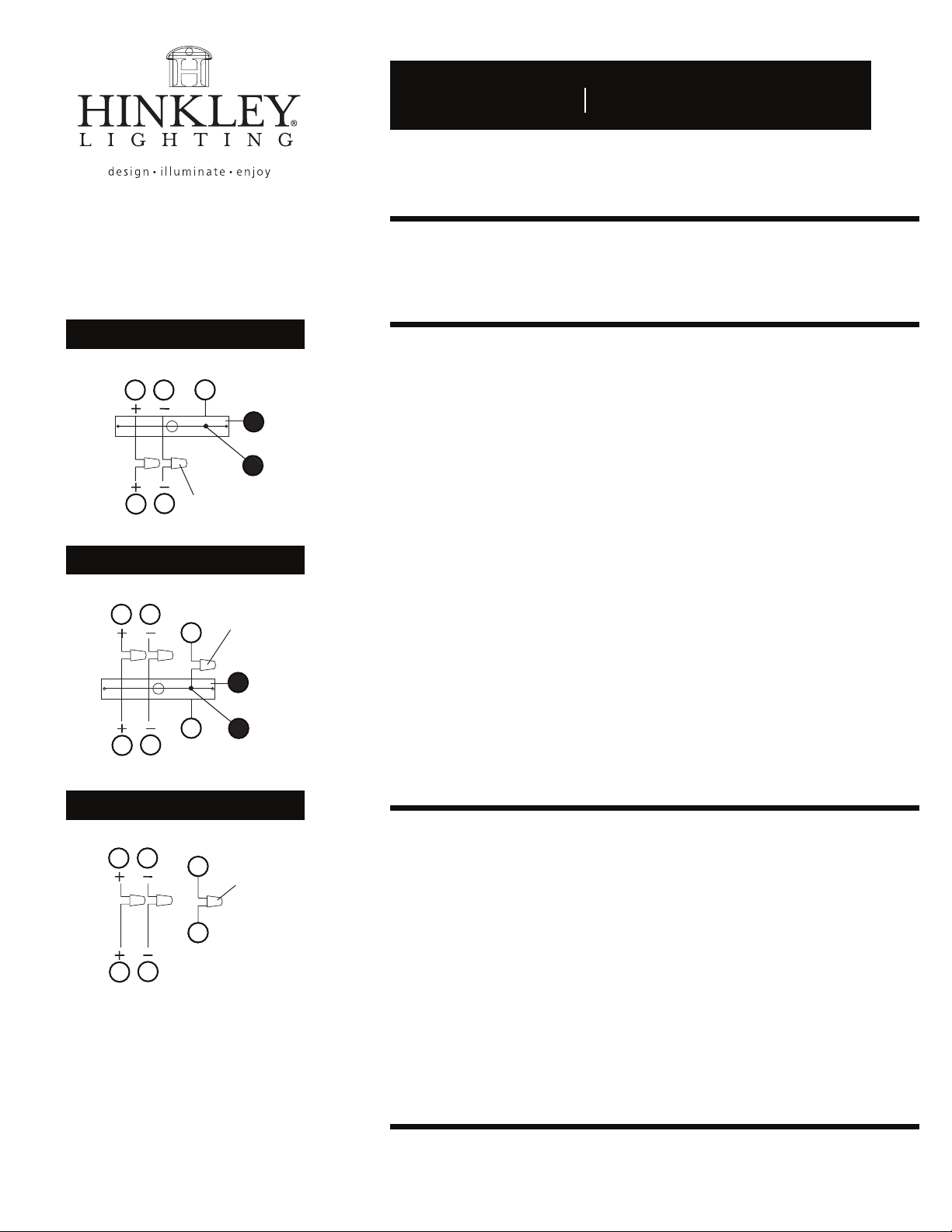
Drawing 1 - Flush Mount
supply wire
A CC
E
I.S. 18 wiring grounding instructions
I.S. 18
SAFETY WARNING: READ WIRING AND GROUNDING INSTRUCTIONS (I.S. 18)
AND ANY ADDITIONAL DIRECTIONS. TURN POWER SUPPLY OFF DURING
INSTALLATION. IF NEW WIRING IS REQUIRED, CONSULT A QUALIFIED
ELECTRICIAN OR LOCAL AUTHORITIES FOR CODE REQUIREMENTS.
wiring instructions
Indoor Fixtures
B
fixture leads
Drawing 2 - Chain Hung
supply wire
connectors
twist-on
D
A C
twist-on
E
E
connectors
1
E
E
D
B
fixture leads
Drawing 3 - Post-Mount
supply wire
A C
2
E
twist-on
connectors
E
D
B
fixture leads
1
2
1. Connect positive supply wire (A) (typically black or the smooth, unmarked
side of the two-conductor cord) to positive fixture lead (B) with appropriately
sized twist on connector - see Drawings 1 or 2.
2. Connect negative supply wire (C) (typically white or the ribbed, marked
side of the two-conductor cord) to negative fixture lead (D).
3. Please refer to the grounding instructions below to complete all
electrical connections.
Outdoor Fixtures
1. Connect positive supply wire (A) (typically black or the smooth unmarked
side of the two-conductor cord) to positive fixture lead (B) with appropriately
sized twist on connector - see Drawings 2 or 3.
2. Connect negative supply wire (C) (typically white or the ribbed, marked
side of the two-conductor cord) to negative fixture lead (D).
3. Cover open end of connectors with silicone sealant to form a watertight seal.
• If installing a wall mount fixture, use caulk to seal gaps between the fixture
mounting plate (backplate) and the wall. This will help prevent water from
entering the outlet box. If the wall surface is lap siding, use caulk and a
fixture mounting platform specially.
4. Please refer to the grounding instructions below to complete all
electrical connections.
grounding instructions
Flush Mount Fixtures
For positive grounding in a 3-wire electrical system, fasten the fixture ground
wire (E) (typically copper or green plastic coated) to the fixture mounting strap (1)
with the ground screw (2) - see Drawing 1.
Note: On straps for screw supported fixtures, first install the two mounting screws in strap.
Any remaining tapped hole may be used for the ground screw.
Chain Hung Fixtures
Loop fixture ground wire (E) (typically copper or green plastic coated) under the
head of the ground screw (2) on fixture mounting strap (1) and connect to the
loose end of the fixture ground wire directly to the ground wire of the building
system with appropriately sized twist-on connectors - see Drawing 2.
Post-Mount Fixtures
Connect fixture ground wire (E) (typically copper or green plastic coated) to power
supply ground with appropriately sized twist-on connector inside post. Cover open
end of connector with silicone sealant to form a watertight seal - see Drawing 3.
HINKLEY LIGHTING 33000 Pin Oak Parkway Avon Lake, OH 44012 800.446.5539 / 440.653.5500 hinkleylighting.com
 Loading...