

Page 1
I.S. 148X glass installation
H I N K L E Y L I G H T I N G 33000 Pin Oak Parkway Avon Lake, OH 44012 800.446.5539 / 440.653.5500 hinkleylighting.com
Family: Richmond
1481 / 1482 / 1487
star t here
I.S. 1481
I.S. 1482
I.S. 1487
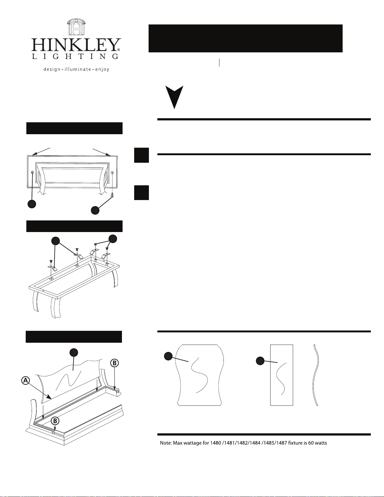
Drawing 1 - Glass Installation
ROOF LEDGE
1
Drawing 2 - Glass Installation
2
1. To install the glass is first necessary to remove the roof from the
fixture. this is accomplished by remove the 2 phillip head screws (1),
located under the roof ledge -see Drawing 1.
1
1. First remove the glass clips (2) from the top of the cage, by
removing phillips head screws (3). Set screws and clips aside for use
later - see Drawing 2.
2
1
3
2. It is necessary to install glass panels in a particular order.
3. First install the large panel of glass (4) by slipping the glass into the
cage. Tilting panel back slightly and slipping the bottom edge (A)
into slot (B) located at the bottom of the cage - see Drawing 3.
4. Install glass clips (2) removed earlier to secure glass in cage.
5. Continue installing glass panels as outlined above, in this order.
Large panels (4) first. Panels are numbered 1 and 2.
6. Small side panels (5) are installed using the same method as the
large panels. The side panels are number 3 and 4.
Make sure to match the curvature of the glass to the cage, before
slipping them in.
6. After all the glass in installed. Fixture can be lamped accordingly
and the roof installed.
Drawing 3 - Glass Installation
4
4
large flat panels
installed first
(panel nos.1 and 2)
5
curved side
panels installed last
(panel nos. 3 and 4)
match
curve
with
cage
01.01.12
Page 2

mounting instructions
Family: Richmond Item No. 1481 / 1487
start here
1. Find a clear area in which you can work.
2. Unpack xture and glass from carton.
3. Carefully review instructions prior to assembly.
1487
1481
Drawing 1 - Fixture Mounting
1. Fixture is mounted using 3 screws.
2. Make all necessary electrical connections following wiring instructions provided.
SAFETY WARNING: READ WIRING AND GROUNDING INSTRUCTIONS (I.S. 18)
AND ANY ADDITIONAL DIRECTIONS. TURN POWER SUPPLY OFF DURING
INSTALLATION. IF NEW WIRING IS REQUIRED, CONSULT A QUALIFIED
ELECTRICIAN OR LOCAL AUTHORITIES FOR CODE REQUIREMENTS.
Make electrical connections from supply wire to xture lead wires. Refer to instruction sheet (I.S.
18) and follow all instructions to make all necessary wiring connections. Then refer back to this
sheet to continue installation of this xture.
1. After wiring connections are complete, slip post tter (A) over top of pre-installed post (B)
making sure all wire connections are tucked inside the pole - see Drawing 1.
2. When xture is slipped over pole make sure no wires are being pinched between the top edge
of the pole and the inside of the post tter.
3. Thread the 3 set screws (C) into pre-tapped holes in post tter.
4. Tighten screws (C) to secure xture to post.
Note: Maximum wattage for 1481 / 1487 xture is 60 watts per bulb.
01.01.12
HINKLEY LIGHTING 12600 Berea Road Cleveland, OH 44111 800.446.5539 / 216.671.3300 www.hinkleylighting.com
 Loading...