


SKID STEER LOADER VERSAPLOW
MODELS 4208, 4210
OPERATOR’S MANUAL
DO NOT USE OR OPERATE THIS EQUIPMENT UNTIL THIS MANUAL
HAS BEEN READ AND THOROUGHLY UNDERSTOOD
PART NUMBER 27000355


Table of Contents 1
TABLE OF CONTENTS
27000355 9/19 MANUALS/27000355
TO THE PURCHASER .................................................................................................................. 2
SAFETY ......................................................................................................................................... 3
OPERATING PROCEDURES .................................................................................................... 4-8
MAINTENANCE ....................................................................................................................... 9-10
TROUBLE SHOOTING ................................................................................................................11
VERSAPLOW ASSEMBLY ..................................................................................................... 12-15
SPECIFICATIONS ....................................................................................................................... 16
WIRING DIAGRAM ..................................................................................................................... 17
HYDRAULIC DIAGRAMS ............................................................................................................ 18
ELECTRICAL PIN LAYOUT ........................................................................................................ 19
WARRANTY ................................................................................................................................ 21
2 To The Purchaser
TO THE PURCHASER
This product is designed and manufactured to
give years of dependable service when properly
maintained and used for the purpose for which
it is intended. Never allow anyone to operate
this equipment until they fully understand the
complete contents of this manual. It is the
responsibility of owners who do not operate this
equipment to ensure the operator is properly
instructed and understands the contents of this
manual. It is also the owner’s responsibility to
ensure that anyone operating this equipment is
mentally and physically capable of so doing.
Important information is contained in this
manual to help ensure safe and efficient
operation.
If you have any questions about this manual, or
the equipment discussed herein, contact your
snowplow dealer.
TAKE NOTE! THIS SAFETY ALERT
SYMBOL FOUND THROUGHOUT THIS
MANUAL IS USED TO CALL YOUR
ATTENTION TO INSTRUCTIONS INVOLVING
YOUR PERSONAL SAFETY AND THE SAFETY
OF OTHERS. FAILURE TO FOLLOW THESE
INSTRUCTIONS CAN RESULT IN INJURY OR
DEATH.
All references to Left or Right are defined as
viewing the plow from the cab of the machine.
This Operator’s Manual is shipped with this
equipment. Contact your dealer for additional
copies.
Always obtain original factory service parts.
Substitute parts could adversely affect
equipment performance and warranty.
Check that your dealer has forwarded the delivery
report form along with the plow identification
number because it helps maintain maximum
service and warranty benefits. This does not put
you on any mailing list, and information thereon
is not available to others.
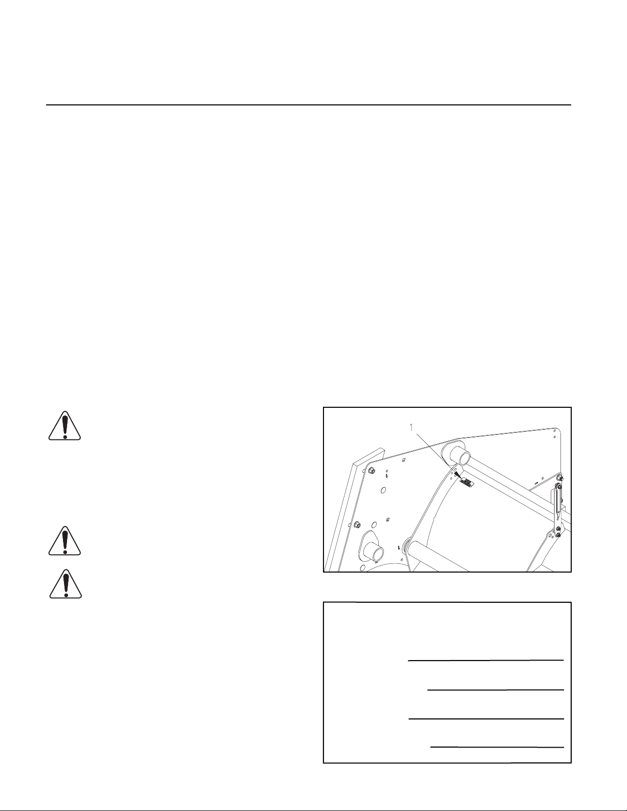
Your plow’s identification number plate is at
location (1) in the following illustration.
THIS SYMBOL MEANS:
- ATTENTION!
- BECOME ALERT!
- YOUR SAFETY IS INVOLVED!
SAFETY SIGNAL WORDS:
DANGER: Indicates an imminently hazardous
situation that, if not avoided, will result in death or
serious injury.
WARNING: Indicates a potentially hazardous
situation that, if not avoided, could result in death
or serious injury.
CAUTION: Indicates a potentially hazardous
situation that, if not avoided, may result in minor or
moderate injury, or damage to components.
NOTE: Addresses safety practices not related to
personal safety.
DWG NO. 7602
Record the following information for later
reference when obtaining service parts:
Purchase Date
Purchaser’s Name
Dealer’s Name
Machine I.D. No.

SAFETY
Safety 3
This is a safety alert symbol. It alerts
an operator to information concerning
personal safety. Always observe
and heed these symbols and instructions,
otherwise death or serious injury can result.
Operator safety is a principle concern in
equipment design and distribution. However,
many accidents occur because a few seconds
of thought, and a more careful approach
to handling, were ignored. Accidents can
be avoided by knowing and following the
precautions cited in this manual.
GENERAL SAFETY
1. Read this manual thoroughly. Make sure
the operator understands it and knows
how to operate this equipment safely. This
equipment can kill or injure an untrained or
careless operator and bystanders. If you
sell this equipment, ensure the new owner
acknowledges receipt of this manual.
BEFORE OPERATION
1. Discipline yourself to visually check for
worn, damaged or cracked parts before
starting use. Replace these with genuine
factory service parts.
2. Escaping hydraulic oil under pressure can
penetrate the skin, causing serious injury.
Do not use your hand to check for leaks.
Use a piece of paper or cardboard to ! nd
suspected leaks. Tighten all connections
before pressurizing hydraulic lines. If " uid is
injected into the skin, get medical attention
immediately to prevent serious infection.
3. Check all controls and operating functions
of the machine in a safe area before starting
to work.
DURING OPERATION
2. This manual Does Not instruct the operation
or maintenance of the skid steer loader.
Obtain training on control and function
of the skid steer loader from your loader
dealer.
3. This plow is intended for plowing snow
only. Plowing gravel, rocks, etc., or using
the plow for any purpose other than plowing
snow could result in harm to the operator
or bystanders or cause damage to the plow
and will void the warranty.
4. Do not attempt to handle or service this
equipment, or direct others to do the same,
unless you know how to do it safely and
have the proper tools for the job.
5. Do not service or otherwise handle a plow
in the raised position unless it is securely
blocked against unexpected falling.
6. Keep hands, feet, hair, and clothing away
from moving parts.
1. Always wear the seat belt and lower the
seat bar, if equipped, when operating the
loader.
2. Make sure all controls are in the neutral
position before starting the loader.
3. Ensure everyone is clear of the machine,
especially away from blind areas of the
operator, before actuating hydraulics or
operating this equipment.
4. Do not plow snow at excessively high
speeds.
5. Avoid hitting objects that will damage your
plow.
6. Set the brakes and stop the loader’s engine
before adjusting or servicing your plow.
AFTER OPERATION
7. Do not alter the equipment to the extent of
compromising safety or performance.
1. Park the plow on a solid, level surface.
4 Operating Procedures
OPERATING PROCEDURES
IMPORTANT: To prevent damage to
snowplow components, skid steer
loaders with a “High Flow/Low Flow”
hydraulic system must be operated in the
Low Flow setting when the plow is attached.
ATTACHING PLOW
Mount the plow on the skid steer loader by
driving the loader into the mount frame, then
set the brakes and relieve hydraulic pressure
before exiting the cab. Secure the plow frame
to the loader as instructed in the loader
manual. Make sure all latches are fully locked
in place to prevent the plow from detaching.
Clean quick couplers of dirt before making
hydraulic connections. Make sure quick
couplers are fully engaged. If quick couplers
do not fully engage, check that the couplers
are the same size and type. Check also to see
that hydraulic pressure has been relieved.
See your loader or attachment dealer for
coupler information.
When using a 7 or 14 pin harness that operates
the plow through the base machines internal
controls operators need to push and hold the
joystick button speci! c to each manufacturer
which will activate a solenoid valve.
Rotate the box ends (forward or backward) by
pushing and holding the appropriate joystick
button speci! c to each machine while directing
oil through the auxiliary ports. Reverse rotation
by pushing and holding the appropriate joystick
button speci! c to each machine while reversing
the oil " ow direction through the auxiliary ports.
Clean electrical connections then check that
the pins and receptacles are aligned before
plugging the connector on the plow into the
connector on the loader.
Test the angling and rotating box end functions
in a safe area before using the plow.
CONTROLLING PLOW FUNCTIONS
Raise and lower the plow by operating the
loader arms as you would for any other
attachment. Avoid tipping the mount plate
forward to apply down pressure on the plow.
Angle the plow left and right by directing oil
through the auxiliary hydraulic ports on the
skid steer loader. Reverse oil flow to angle
the blade the opposite direction.
Release the hydraulic flow controller to hold
the blade at an angle position between full
left or full right. If the plow angles opposite
from what is expected, switch couplers on the
two feed hoses that connect to the loader.
DWG NO. 7603
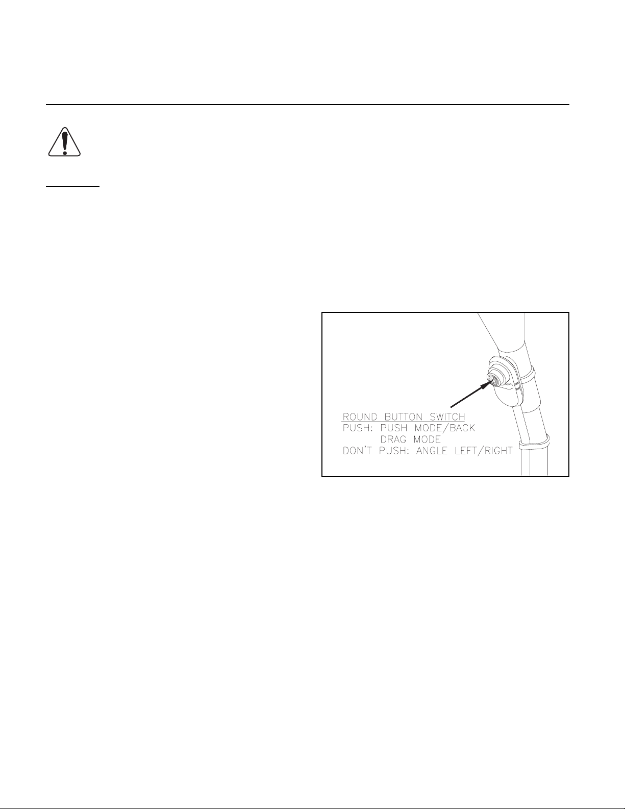
When using a Fox universal controller rotate
box ends rearward by pushing and holding the
round button switch while directing oil to the
auxiliary ports on the skid steer loader putting
the plow in back drag mode.
Rotate box ends forward by pushing and holding
the round button switch while reversing the oil
flow direction to the auxiliary hydraulic ports on
the loader to put plow in push mode.
To hold box ends at an intermediate position
between full forward or full back, release
hydraulic flow controller, then release round
button switch.
Box ends will move more freely if rotating box
end functions are done with plow in raised
position to avoid resistance from ground.
TRANSPORTING PLOW
Raise plow to a position where it does not block
your view forward. Transport plow with hydraulic
flow off or in neutral to prevent accidental
lowering of plow. Never adjust blade position
while driving.
PLOWING SNOW
WARNING: Always wear seat belt
and lower seat bar, if equipped, when
plowing snow. Sudden contact with a
hidden object can result in serious personal
injury.
Inspect areas to be plowed before snowfall for
potential hazards, and mark obstructions with
stakes that will be seen when snow covers the
ground. Identify any emergency equipment and
utility outlets that may need to be cleared in the
event of a storm. Prepare a plan beforehand for
clearing snow from tight or enclosed areas and
locate sites for stacking snow.
Operating Procedures 5
DWG NO. 7742
To back drag snow away from a parking stall or
building, lift plow up off of ground and straighten
plow across loader. Rotate box ends all the way
rearward.
Set the loader lift arms into the float mode so
the plow can follow the contour of the ground
and clean up low areas while plowing snow.
Always plow snow as it is accumulating. Wet
snow may weigh about 12 pounds per cubic
foot. The weight of snow being pushed by your
plow may increase to several tons.
Allowing snow depth to grow to unmanageable
levels can cause difficult removal problems and
can be costly in terms of wear on equipment.
WARNING: Serious personal injury
can result from plowing at excessive
speeds, as well as costly damage to
equipment and property, if an obstruction is
encountered while plowing. Do not exceed
10 mph while plowing.
DWG NO. 7743
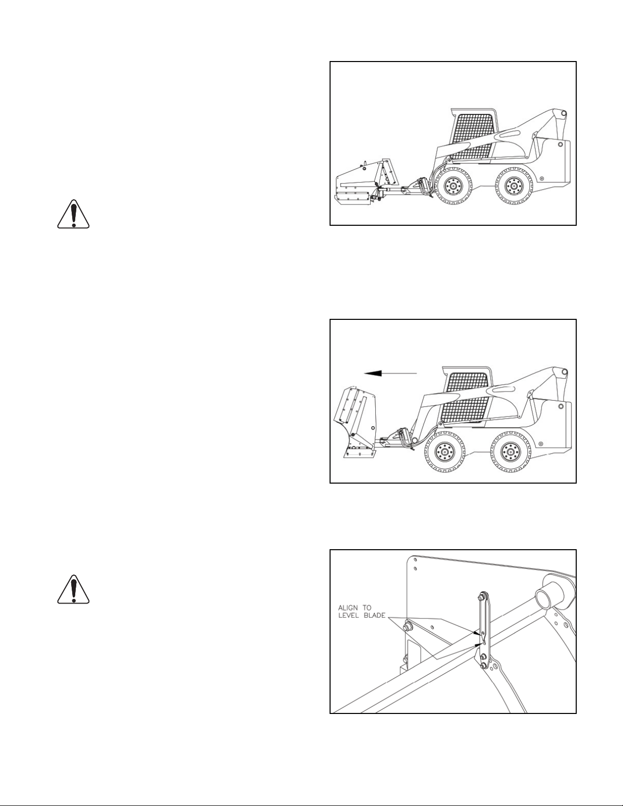
Slowly drive into area to be cleaned out lower
cutting edge to ground.
DWG NO. 7744
Tilt plow blade to align level indicators.

6 Operating Procedures
DWG NO. 7745
Slowly back drag snow away from parking stall
or building to an open area.
DWG NO. 7742
After back dragging successive passes to
accumulate a pile of snow. Rotate box ends all
the way forward. Verify leveling bars are plumb
and adjust loader mount plate angle as needed.
Push and stack snow in a clear area away from
the path of vehicle travel.
DWG NO. 7608
Clear large lots by angling blade and creating a
single path. Push snow to outer edges of lot by
taking successive passes with blade angled.
DWG NO. 7747
Plow box ends can be rotated slightly rearward
allowing operator to clean curbs easier in plow
angled position. Rotate sides so lowest point
is higher than curb. Partially rotated sides
also help contain large amounts of snow while
windrowing large parking lots.
When plowing very deep snow, it may be
necessary to raise blade and shear off layers
of snow until a working area is cleared. Work
small areas in multiple passes to push snow to
outer edges.
Generally, 6 inch snow accumulation can be
plowed with the entire blade width; 9 inch snow
accumulation with 3/4 of the blade width; 12
inch snow accumulation with 1/2 of the blade
width. Local conditions will determine how much
work can be done before stalling or losing tire
traction.

HITCH OPTIONS
There are (2) hitch options for the VersaPlow,
fixed and floating.
DWG NO. 7748
The fixed hitch is recommended for rear wheel
and (4) wheel drive vehicles including skid
steers, Toolcats, etc.
Operating Procedures 7
DWG NO. 7750
This hitch is recommended for front wheel drive
and some 4 wheel drive vehicles where slight
down pressure on plow can cause operators to
have a difficult time steering and getting traction
during snowplowing. Another advantage is
cutting edges last longer with reduced down
pressure on them.
DWG NO. 7749
The other option is a floating hitch which has a
floating upper link to allow the plow to ride on
the contour of the ground. This option makes it
more difficult to put down pressure on plow.

8 Operating Procedures
ADJUSTING OUTER CUTTING EDGES
Periodically after finishing snowplowing check
height of box end urethane cutting edges in
both push and back drag mode with respect to
main cutting edge. It is recommended to have
the box end cutting edges 1/4” higher than the
main cutting edge. If the box end edges are
higher than 1/4” off the ground or are lifting the
main cutting edge off the ground, the box end or
main cutting edges need to be adjusted.
REMOVING PLOW
Park the plow on a solid level surface with the
blade straight across the loader.
Lower the blade to the ground, relieve hydraulic
pressure and set the brakes on the loader.
Uncouple the hydraulic feed lines from the
loader and unplug the electrical connector.
Replace any dust caps at this time.
Unlatch the attachment mechanism at the front
of the loader then slowly drive the loader back
away from the plow.
DWG NO. 7746
Using a 1/4” thick block of wood or other
shimming material, loosen box end cutting edge
bolts and raise plow slightly if necessary, and
insert 1/4” shim blocks under box end urethane
cutting edges. Lower main plow cutting edge to
the ground, with plow edge on ground and 1/4”
shims under box wing cutting edges.
Tighten 1/2” carriage bolts until metal on outside
plates slightly deforms into slots of cutting
edges. This will prevent cutting edges from
sliding up or down during operation.
Perform similar procedure to check back drag
cutting edge heights. Adjust as needed and
again tighten hardware so outside plates slightly
deform to hold urethane cutting edge in place.

Maintenance 9
Section 9
MAINTENANCE
WARNING: Do not service or otherwise
handle a plow in the raised position
unless it is securely blocked against
unexpected falling.
Dependable snowplow operation is the result of
following good maintenance procedures. Inspect
your plow frequently to ensure that all parts are
working smoothly, and develop a schedule for
maintenance at required intervals.
GENERAL
Wash salt and dirt off the plow before storage.
Do not power wash hydraulic cylinders, as high
pressure can damage seals and cause cylinder
failure. Touch-up any chips or scratches in the paint
and apply a light coating of grease to extended
cylinder rods to prevent corrosion.
MECHANICAL COMPONENTS
TITLE
GRADE 5 TYPE B & F LOCK NUT TORQUES
Size Ft-lbs. N-m
5/16” 13-18 17-25
3/8” 23-33 31-44
1/2” 58-82 79-112
5/8” 117-165 158-223
GRADE 5 BOLT TORQUES*
Size Ft-lbs. N-m
1/4” 8-12 11-16
3/8” 29-41 39-56
1/2” 73-103 99-140
5/8” 146-206 198-279
*Applications without lock nuts.
Loose bolts can cause hole elongation and
part failure resulting in dangerous operating
conditions and equipment breakdown.
Prior to the operation of a new snowplow, or
one which has been stored, inspect all hardware
and verify proper torque on all bolts and nuts
in accordance with the recommended torque
speci! cations.
Check all hardware periodically during operation
and keep tightened to speci! ed torques. Replace
worn bolts and lock nuts with grade 5 bolts and
equivalent type B or type F lock nuts. Type B
lock nuts are plain hex; type F lock nuts are
" anged hex.
Inspect wear of cutting edges before every
plowing season and frequently throughout the
season. Adjust or replace cutting edges before
wear reaches the main plow blade.

10 Maintenance
ELECTRICAL MAINTENANCE
Periodically check all electrical connections for
proper • t and remove any contamination, that
may be present.
To prevent contamination, always place dust caps
on connectors when not in use. This is particularly
important when the plow is being stored. The
use of dielectric grease is recommended to
reduce corrosion of the contacts and to make
connecting and disconnecting easier.
Before each season check loader battery and
electrical system for proper operation. A weak
battery, dirty terminals, or faulty charging system
may cause improper operation.
LUBRICATION
Periodically throughout the year between
snowfalls, grease all pivot points on plow as
shown in diagrams. Look for grease decals to
help with zerk locations.
DWG NO. 7751
DWG NO. 7752

Trouble Shooting 11
Section 11
TROUBLE SHOOTING
GENERAL
1. Check to see that the plow and loader are
wired correctly with clean, tight connections
at the battery. Check for proper voltage.
2. Check that hydraulic quick couplers are
fully engaged and electrical connection is
tight at the front of the loader.
PROBLEM
1. Hydraulic cylinder does
not function or functions
slowly when hydraulics are
activated.
A. Weak or defective loader
B. Oil level low.
C. Hydraulic connection leak.
D. Solenoid valve not opening
TITLE
POSSIBLE CAUSE
battery.
properly.
3. Check the hydraulic oil level in the skid
steer loader.
4. Check for external leakage at cylinders,
hoses and valve manifold.
REMEDY
A. Charge or replace battery.
B. Add oil (do not over! ll).
C. Tighten or redo connection.
D. Replace valve.
2. Plow angles opposite
expected direction.
3. Oil leaks from cylinder(s).
4. Angling cylinders relieve
too easily or too dif! cultly
while plowing.
5. Plow does not clean-up
snow from low areas.
6. Battery goes dead with
power on the loader.
7. Hydraulic quick couplers
don’t connect.
A. Feed hoses reversed.
A. Loose packing.
B. Defective cylinder.
A. Relief pressure set too low
or too high.
A. Loader arms not in " oat
mode.
A. Short in wiring.
A. Wrong size or type of
couplers.
A. Switch quick couplers on
feed hoses.
A. Tighten packing nut 1/8
turn.
B. Repack or replace cylinder.
A. Have relief pressure
adjusted by skidsteer
dealer.
A. Loader arms should be in
" oat mode.
A Locate and repair.
A. Verify matching couplers.
B. Oil pressure in loader lines.
B. Relieve hydraulic pressure
in loader.

12 VersaPlow Assembly
12 Section
VERSAPLOW ASSEMBLY
GENERAL INFORMATION
WARNING: To prevent personal injury
or death, be certain to keep clear of any
parts that may drop when removing
bundling straps, wires or brackets. Support
heavy sections with hoist or blocks before
removing wires or straps.
Be certain that hydraulic hoses and electrical
wires are safely routed and allow full motion of
moving parts. Secure loose hoses and wires
with plastic tie straps.
PLOW ASSEMBLY
1. Lift moldboard assembly by hooking to
inner ribs and bring to a clear level area.
TITLE
Insert main pivot pin so formed lip is pointing
rearward. Slide the washer onto the bottom
of the pin, then secure the assembly with
the slotted nut and cotter pin. Tighten the
nut so the assembly is secure, but pivots
freely.
DWG NO. 7753
2. Remove shipping brackets and shipping
stop brackets from outside ribs if supplied
with moldboard assembly.
3. Stabilize moldboard assembly using blocks
or secure on lifting mechamism. Move the
hitch frame to the back of the moldboard
and align pivot pin bushings.
DWG NO. 7754
Pin rod ends between lugs on the moldboard
with 3/4 inch x 3 1/4 inch clevis pin and
cotter pins from the parts box.
4. Install two straight hydraulic adapters from
the parts box into both ports of the rollover
cylinder.
DWG NO. 7755
Tighten two 90° Flare/Swivel nut adapter
onto straight ! tings, directed as shown.

5. When installing a Versa Plow with the
ocillating/fl oating hitch option on a loader
with with taller snow tires, remove and
reinstall two rear push frame bolts through
the upper set of holes to allow more
downward travel of the blade.
Floating Hitch Height Adjustment DWG NO. 7756
VersaPlow Assembly 13
Oscillating Hitch Hose Routing DWG NO. 7758
Tie hoses together and route along the
frame, as shown. Ensure hoses have
adequate length for cylinder extension/
retraction, and will not be pinched in rotating
stop plates before securing to the frame
with plastic tie straps.
6. Refer to the appropriate drawing below
for hose routing along the different hitch
frames.
Fixed Hitch Hose Routing DWG NO. 7757
Route hydraulic supply and return hoses
through U-Bolts on the mount plate up to
couplers on the loader. Tie hoses where
they will not drag on the ground or get
caught in loader tires.
7. Assemble hose ends to rollover cylinder as
follows:
- Port C3 to rotation cylinder rod end.
- Port C4 to rotation cylinder fi xed end.
DWG NO. 6694
Refer to labels on hose ends to ensure
hoses are connected correctly.

14 VersaPlow Assembly
8. Attach two leveling bars onto the ribs using
provided 5/16 hardware.
DWG NO. 7759
Verify top bar rotates freely on bushing after assembly.
QUICK COUPLERS
IMPORTANT: Damage to the wiring
harness will occur if adequate cable
length is not provided to allow for
full motion of the loader arms. Use plastic
tie straps to secure the wiring harness to
the loader arm immediately adjacent to the
loader arm pivot point.
Refer to drawing number 7627. Fasten the
square connector next to the hydraulic quick
couplers. Route the cable along the skid-steer
arm to the pivot point of the arm and secure with
the supplied plastic tie straps. It is especially
important to leave adequate cable at the pivot
point to allow for arm movement.
Next, the switch cable needs to be routed into
the cab. Attach the switch to the control arm
using a plastic tie strap as shown in drawing
number 4284.
Select and install hydraulic quick couplers
and adapter ! ttings on VersaPlow feed lines
according to the size and type (i.e. " at face or
poppet style) of couplers on customers machine.
Hoses supplied on VersaPlow have 9/16-18
JIC female swivel ends for 9/16-18 JIC male
adapters.
UNIVERSAL CONTROLLER
ELECTRICAL WIRING
Identify the electrical control cable purchased
with the snowplow. It has a square 4-pin
weather pack connector on the ! rst end, two ring
terminals on the second end, and a single push
button switch on the third end.
DWG NO. 4284
Route the third length of the cable to the battery.
Connect the red fused wire ring terminal to the
positive post of the battery and the black wire
ring terminal to the negative post of the battery.
Ensure all wires are away from hot or moving
parts, and secured with plastic ties to prevent
damage.
DWG NO. 7627
The wiring on the plow comes preinstalled. The
connectors to the solenoids should be ! rmly
seated. The connectors are interchangeable, as
both solenoids are activated at the same time
when the push button switch is pressed.

VersaPlow Assembly 15
Refer to Operating Procedures section for
attaching and operating the plow. Test that all
functions are working properly and that cabling
is not being stretched or pinched.
14 PIN OR 7 PIN ELECTRICAL HARNESS
Locate 7 or 14 pin wiring harness purchased with
plow. Insert 4 pin plug into mating connection
from plow. Electrical wiring from plow is inside
sleeve of hydraulic hose, and connector is
located near hydraulic couplers from plow. Insert
14 or 7 pin connectors into machines mating
connector.
ADJUSTING OUTER CUTTING EDGES
Check height of box end urethane cutting edges
in both push and back drag mode with respect
to main cutting edge. Box end cutting edges
should be 1/4” higher than the main cutting
edge. If the box end edges are more than 1/4”
off the ground or are lower than the main cutting
edge adjust the cutting edges, as follows.
DWG NO. 7629
Refer to loader operator’s manual for list of
functions on proper attachment control.
In some cases 14 pin plug layout needs to be
modi! ed for speci! c machines. Refer to table on
page 19 for pin layout.
If pin layout needs to be modi! ed refer to
instruction sheet with 14 pin harness for
instructions to change pin layout. Refer to
loaders wiring diagram on pin layout.
DWG NO. 7746
Using a 1/4” thick block of wood or other
shimming material, loosen box end cutting edge
bolts and raise plow slightly if necessary, then
insert 1/4” shim blocks under box end urethane
cutting edges. Lower main plow cutting edge to
the ground, with plow edge on ground and 1/4”
shims under box wing cutting edges.
Tighten 1/2” carriage bolts until metal on outside
plates slightly deforms into slots of cutting
edges. This will prevent cutting edges from
sliding up or down during operation.
Perform similar procedure to check back drag
cutting edge heights. Adjust as needed and
again tighten hardware so outside plates slightly
deform to hold urethane cutting edge in place.

16 Section
16 Specifications
SPECIFICATIONS
Models 4108 4208 4110 4210
Blade Width 8’ 8’ 10’ 10’
Overall Width 8’ 8” 8’ 8” 10’ 8” 10’ 8”
Blade Height 30 1/2” 30 1/2” 30 1/2” 30 1/2”
Weight
(Moldboard & Wings Only)
Weight
Fixed Hitch
807 lbs. 938 lbs. 911 lbs. 1,075 lbs.
TITLE
311 lbs.
Weight
Floating Hitch
Cutting Edge
Feed Hose Ends 9/16-18 JIC Female Swivel
Wiring Harness Fuse 10 AMP
1 1/2” x 8”
Polyurethane
1/2” x 6”
Steel
474 lbs.
1 1/2” x 8”
Polyurethane
1/2” x 6”
Steel

Wiring Diagram 17
Section 17
UNIVERSAL CONTROLLER WIRING DIAGRAM
TITLE
DWG NO. 4286

18 Hydraulic Diagrams
DWG NO. 7618

Electrical Pin Layout 19
Skid Steer Electronic Pin Layout
Pin A B C D
Bobcat 14 Pin LH L/R (-) Gnd LH Center L LH Center R
Case 14 Pin N/A (-) Gnd Button 2 LH Handle Dn Button 2 LH Handle Up
Cat 14 Pin LH Trigger Aux 7 (-) Gnd C-Control Aux 5 C+ Control - Aux 6
JCB/Volvo 14 Pin N/A (-) Gnd C-SW FWD C-SW BWD
John Deere (-) Gnd N/A Right Down Left Down
Kubota 14 Pin
SVL75/90/95 Standard
Kubota Extended 14 Pin
Add-On Kit
New - NH 14 Pin N/A (-) Gnd LH #3 - Dn LH #3 - Up
Old - NH 14 Pin N/A (-) Gnd SW3 MOM Dn SW MOM Up
Takeuchi N/A (-) Gnd SW1 Up R Joy/L Up SW 1 Dn R Joy/L Down
Yanmer N/A (-) Gnd SW1 Up SW 1 Dn
Mustang N/A (-) Gnd SW1 Up SW 1 Dn
Gehl SW 4 (-) Gnd SW1 Up SW 1 Dn
Terex (-) Gnd LH-SW Dn LH - Right LH - Left
Wacker 14 Pin N/A (-) Gnd LH Center L LH Center R
N/A (-) Gnd LH Switch RH Switch
N/A (-) Gnd Button #1 Button #2

20 Notes
NOTES:

Warranty 21
HINIKER WARRANTY
SKID STEER SNOWPLOW LIMITED WARRANTY
The only warranty Hiniker gives and the only warranty that any Hiniker dealer is authorized to give on behalf
of Hiniker is as follows: (NO EMPLOYEE OR REPRESENTATIVE IS AUTHORIZED TO CHANGE THIS
WARRANTY IN ANY WAY OR GRANT ANY OTHER WARRANTY.)
Hiniker warrants to the original purchaser of a Hiniker snowplow that Hiniker will repair or replace any
defects in material and workmanship that occur within one year from date of retail delivery.
Hiniker’s obligation and liability under this warranty is expressly limited to repairing or replacing, at Hiniker’s
option, at an authorized Hiniker dealer location, the defective parts at no charge to the original purchase.
Hiniker MAKES NO OTHER WARRANTY, EXPRESS OR IMPLIED AND MAKES NO WARRANTY OF
MERCHANTABILITY OR OF FITNESS FOR ANY PARTICULAR PURPOSE.
HINIKER’S OBLIGATION UNDER THIS WARRANTY SHALL NOT INCLUDE ANY TRANSPORTATION
CHARGES TO OR FROM THE AUTHORIZED HINIKER DEALER LOCATION OR ANY LIABILITY FOR
INCIDENTAL, INDIRECT OR CONSEQUENTIAL DAMAGE OR DAMAGES OF ANY KIND FOR LOST
PROFITS OR DELAY. If requested by Hiniker, products or parts for which a warranty claim is made are to
be returned freight prepaid to our factory. Any improper use, operation beyond rated capacity, substitution
of parts not approved by Hiniker, or any alteration or repair in such manner as in our judgment affects the
product materially and adversely shall void this warranty.
Hiniker reserves the right to make improvements or changes to any of it’s products without notice. Such
improvements or changes shall not trigger any obligation by Hiniker to update, modify or change any
products previously sold by Hiniker.
Hiniker does not warrant the following:
1. Used products.
2. Any product that has been repaired, modi! ed or altered in a way not approved by Hiniker.
3. Depreciation or damage caused by normal wear, lack of reasonable and proper maintenance, failure
to follow Operators Manual Instructions, misuse, lack of proper protection during storage, or accident.
4. Parts replacement and service necessitated by normal wear or maintenance including, but not
limited to, cutting edges, hoses, and hardware.
5. Paint ! nish damage caused by normal wear.
Hiniker does not assume any liability for any damage to a vehicle resulting from the attachment or use of a
Hiniker snowplow. Attachment of a Hiniker snowplow to a vehicle is at the risk of the purchaser.
It is the responsibility of the original snowplow purchaser to verify the original date of purchase.
A DELIVERY REPORT FORM must be ! lled out and received by Hiniker with 30 days of retail delivery at
the address below to initiate the warranty coverage.
HINIKER COMPANY
58766 240th St.
MANKATO, MN 56002
PHONE (507) 625-6621 -- FAX (507) 625-5883
www.hiniker.com
 Loading...