


MODEL AR-2000
30 FT. FLAIL SHREDDER
OPERATOR’S MANUAL
DO NOT USE OR OPERATE THIS EQUIPMENT UNTIL THIS MANUAL
HAS BEEN READ AND THOROUGHLY UNDERSTOOD
PART NUMBER 79203563


Table of Contents 1
Section 1
TABLE OF CONTENTS
79203563 2/13 Manual/79203563
ASSEMBLY ..........................................................................................................................................33-39
Skid Shoes ........................................................................................................................................38
Grass Divider .....................................................................................................................................39
Basic Machine ..............................................................................................................................33-38
Off-loading ......................................................................................................................................... 33
FIELD PREPARATION .........................................................................................................................10-13
End Transport Towing ........................................................................................................................ 12
PTO’s .................................................................................................................................................10
Rockshaft & Wheels ...........................................................................................................................11
Trailing Hitch ......................................................................................................................................10
Tractor ............................................................................................................................................... 10
TITLE
GENERAL
Specications .......................................................................................................................40
To Purchaser .......................................................................................................................... 2
Storage .................................................................................................................................16
LUBRICATION .............................................................................................................................18
OPERATION ...........................................................................................................................14-17
End Transport Towing ...........................................................................................................15
General.................................................................................................................................14
Trailing Hold Height Adjustment ........................................................................................... 15
SAFETY
......................................................................................................................................... 9
Before Operation .................................................................................................................... 4
Decal Location........................................................................................................................6
During Operation .................................................................................................................... 4
General...................................................................................................................................3
Service ................................................................................................................................... 5
Towing .................................................................................................................................... 5
SERVICE ................................................................................................................................23-32
Belts ..................................................................................................................................... 25
Drive Shaft Bearings ............................................................................................................ 29
Gearbox................................................................................................................................30
Hardware .............................................................................................................................. 23
Knives...................................................................................................................................23
Rotor Bearings ..................................................................................................................... 25
Sheaves ............................................................................................................................... 28
Wheel Bearings .................................................................................................................... 29
TROUBLESHOOTING ................................................................................................................22
WARRANTY ................................................................................................................................ 41
2 Section
2 To The Purchaser
TO THE PURCHASER
This product is designed and manufactured to
give years of dependable service, when properly
maintained and used for the purpose for which
it is intended. Never allow anyone to operate
this equipment until they fully understand the
complete contents of this manual. It is the responsibility of owner’s, who do not operate this
equipment, to insure the operator is properly instructed and is fully aware, and understands, the
contents of this manual. It is also the owner’s responsibility to insure that anyone operating this
equipment is mentally and physically capable of
so doing.
Important information is contained in this manual
tohelpinsuresafeandefcientoperation.
If you have any questions about this manual, or
the equipment discussed therein, contact your
HINIKER dealer.
TITLE
ONE COPY IS TO BE GIVEN TO YOU. DO NOT
ACCEPT THIS EQUIPMENT UNTIL YOU ARE
SATISFIED ALL ITEMS THEREON HAVE BEEN
CHECKED, AND YOU UNDERSTAND THEM.
Check that your dealer has forwarded the
HINIKER delivery report copy, along with the
machine serial number, because it helps main-
tain maximum service and warranty benets.
This does not put you on any mailing list and
information thereon is not available to others.
THIS IS THE SAFETY ALERT SYMBOL.
IT ALERTS AN OPERATOR TO INFOR-
MATION CONCERNING PERSONAL
SAFETY. ALWAYS OBSERVE, AND HEED,
THESE INSTRUCTIONS, OTHERWISE DEATH,
OR SERIOUS INJURY CAN RESULT!
All references to LEFT or RIGHT means viewing the equipment from the rear and facing the
tractor.
Additional copies of this manual are available
from your Hiniker Dealer
ALWAYS OBTAIN ORIGINAL HINIKER SERVICE PARTS BECAUSE SUBSTITUTE PARTS
COULD ADVERSELY AFFECT EQUIPMENT
PERFORMANCE AND WARRANTY.
All photos in this manual refer to paragraph(s)
preceding the photo.
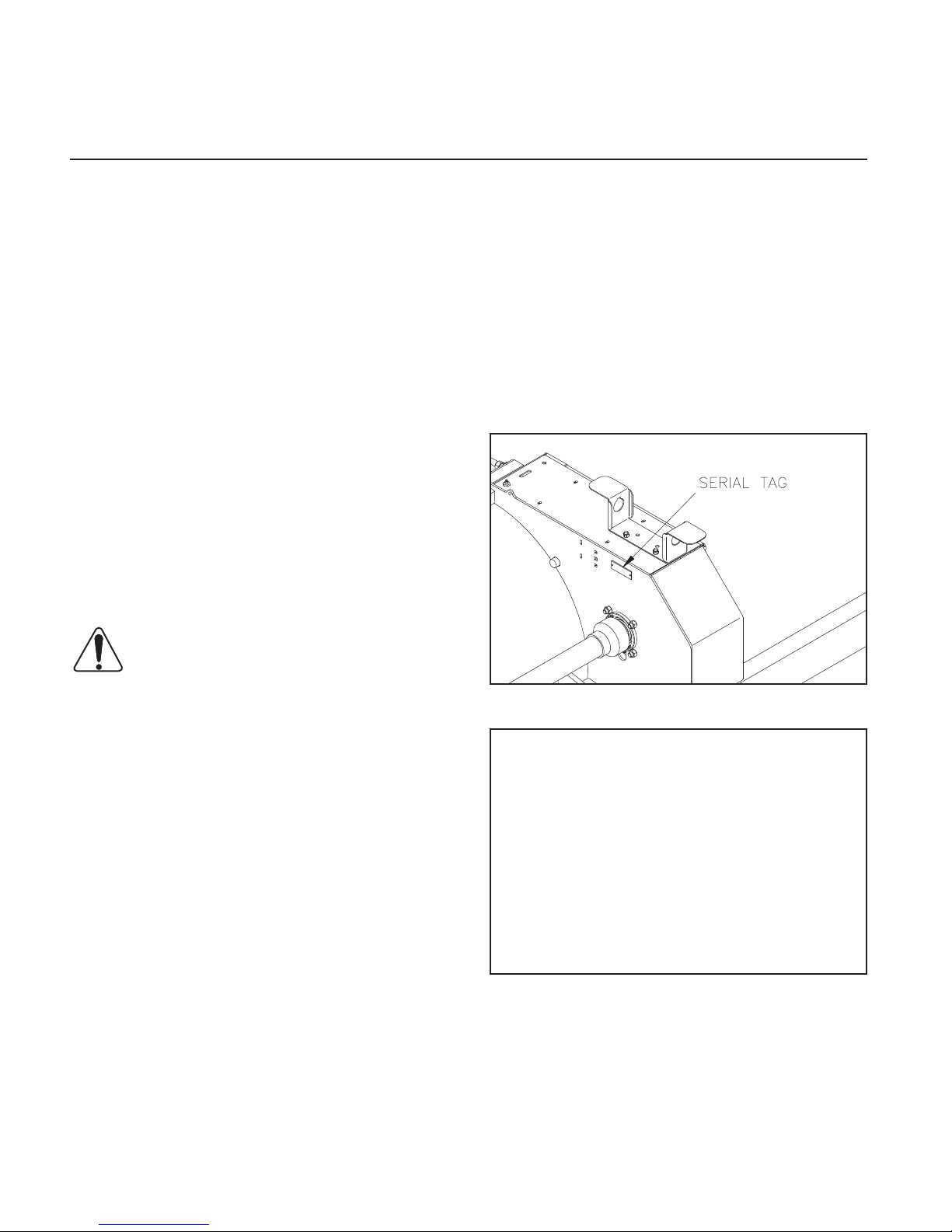
FIGURE 1 DWG NO. 6864
Record the following information for later
reference when obtaining service parts:
Purchase Date:________________________
Purchaser’s Name:_____________________
Dealer’s Name:________________________
Machine Serial #:_______________________
3 COPIES OF THE DELIVERY REPORT ARE
TO BE FILLED OUT BY YOUR HINIKER DEALER WHEN YOU ACCEPT THIS EQUIPMENT.

TITLE
SAFETY
Safety 3
Section 3
THIS IS THE SAFETY ALERT SYMBOL.
IT ALERTS AN OPERATOR TO INFOR-
MATION CONCERNING PERSONAL
SAFETY. ALWAYS OBSERVE, AND HEED,
THESE SYMBOLS AND INSTRUCTIONS, OTHERWISE DEATH, OR SERIOUS INJURY CAN
RESULT!
Operator safety is a principle concern in equipment
design and distribution. However, many accidents
occur because a few seconds of thought, and a
more careful approach to handling, were ignored.
ACCIDENTS CAN BE AVOIDED BY KNOWING,
AND, FOLLOWING, THE PRECAUTIONS CITED
IN THIS MANUAL.
For better viewing, certain photos may show a
safety shield open or removed. This equipment
should never be operated without factory installed
shields in place.
Replace any decals that are not readable, or missing. Their ordering numbers and proper location
are shown in the DECAL LOCATION section of
this manual. Keep decals free of dirt, grease, etc.
Throughout this manual, and on all safety related
decals, a safety alert symbol, along with the signal
word CAUTION, WARNING or DANGER will be
found.Thesearedenedasfollows:
CAUTION: A reminder for proper safety
practices and directs attention to fol-
lowing them. Decals of this class are
yellow and black.
WARNING: A reminder for proper safety
practices and what can happen if they
are ignored. This has a more serious
consequence than CAUTION. Decals of this
class are orange and black.
There are other decals, and copy, in this manual
that pertain to protecting the equipment. They are
not directly related to operator safety. These have
black letters on a white background to distinguish
them from safety decals. They lack the safety alert
symbol, but carry the words NOTICE or IMPOR-
TANTdenedasfollows:
NOTICE: INFORMS THE READER OF SOMETHING THAT CAN CAUSE MINOR MACHINE
DAMAGE, OR POOR PERFORMANCE, IF IGNORED.
IMPORTANT: WARNS THE READER OF POTENTIALLY MORE SERIOUS MACHINE DAMAGE, OR POOR PERFORMANCE IF IGNORED.
GENERAL
1. Additional copies of this operator’s manual
are available from your HINIKER dealer. If you
sell this equipment, insure the new owner acknowledges receipt of this manual.
2. Read this manual thoroughly. Make sure the
operator understands it and knows how to operate this equipment safely. Farm equipment
can kill or injure an untrained, or careless, operator.
3. Do not attempt to handle and service this
equipment, or direct others to do the same,
unless you know how to do it safely.
4. Keep all shields and guards in place.
5. Keep hands, feet, hair and clothing away from
moving parts.
6. Disengage PTO, stop tractor engine, set
brakes and wait for all motion to stop before
adjusting, or servicing, this equipment.
DANGER: Denotes a most serious safety hazard. It is a reminder for observing
the stated precautions and what can
happen if they are ignored. Decals of this class
are red and white.
7. Keep off, keep others off, and insure everyone
is clear before starting, actuating hydraulics,
and during equipment operation.

4 Safety
8. Do not service, or otherwise handle, a
shredder in a raised position unless it is
securely blocked against unexpected falling.
9. Keepallfrontippershieldsinplaceandfree
swinging.
10. Never shred in areas littered with glass, rocks,
metal, etc. Use cab tractor if operating in
unfamiliar areas. Keep cab windows clean to
maintain good visibility.
11. Escapinghydraulic/dieseluidunderpressure
can penetrate the skin causing serious injury.
DO NOT use your hand to check for leaks. Use a
piece of cardboard.
Stop tractor and relieve pressure before connecting/
disconnecting lines.
Tighten all connections before pressurizing
hydraulic lines.
Ifuidisinjectedintotheskin,getmedicalattention
to prevent serious infection.
12. Discipline yourself to always visually inspect
this equipment for any excessively worn,
damaged, or cracked parts before starting
use. Replace these with genuine HINIKER
parts.
13. Stalk shredding often involves a combustible
environment. Carry a re extinguisher and
rstaidkitwithtractor.
BEFORE OPERATION
1. Insure unit’s PTO assembly is fully engaged
with gearbox and tractor shafts and SLIDING
COLLARS ARE RETURNED TO THEIR
LOCKED POSITIONS.
2. NEVER allow improperly supervised minors,
or anyone else, to operate this equipment. It is
your responsibility to insure that any operator
is mentally and physically capable of so doing.
3. Do not operate a 1000 RPM shredder with a
540 RPM tractor.
4. Do not “jump start” the tractor from along side
it. Start tractor only from seat.
5. Lock any swinging tractor drawbar before
hooking up. Use a cross retainer in end of the
hitch pin.
6. Disengage PTO, stop tractor engine, and
remove key before hooking up shredder PTO.
7. Clear area of people, and debris, before
engaging tractor PTO Be alert for blind areas
of operator. Slow down PTO and “feather” into
engagement to prevent unnecessary stress
on shredder’s driveline.
8. DO NOT OPEN MACHINE SHIELDS WITH
TRACTOR ENGINE RUNNING.
9. Do not stand close to, immediately behind or
in front of, a running shredder.
14. OSHA requires farm employers to meet certain
safety standards. Become familiar with, and
comply with them.
15. Do not alter this equipment to the extent of
compromising safety and performance.
16. Do not substantially operate tractor in a closed
building.
17. Ag chemicals can be dangerous. Always follow
the manufacturer’s label safety precautions
when using them.
18. Do not assume everyone is as safety
conscious as yourself.
DURING OPERATION
1. Gradually bring unit up to operating speed
and check for any abnormal vibration, or
performance. IF ABNORMAL VIBRATION
IS PRESENT AT ANY TIME, IMMEDIATELY
DISENGAGE PTO, STOP TRACTOR
ENGINE, REMOVE KEY AND DETERMINE/
CORRECT CAUSE BEFORE PROCEEDING.
2. Disengage PTO, stop tractor engine, remove
key and allow EQUIPMENT TO COME TO A
COMPLETE STOP before:
- Cleaning, unclogging, lubricating, inspecting,
or otherwise servicing, any part of this
equipment.

Safety 5
- Connecting or disconnecting the shredder
from the tractor.
- Allowing anyone else near the equipment.
- Dismounting from the tractor seat and parking
the equipment.
- Placing any part of your body in dangerous
proximity to shredder.
3. When parking this equipment, lower it to full
“down” position. Set the tractor brakes and
block wheels if on an extreme slope.
TOWING
1. When towing on public highways:
- Use a safety chain between the shredder hitch
and the towing vehicle (The 10,000# safety
chain is part number 85501539).
- Be sure end transport hydraulic cylinder locks
are in place.
- Use a tractor of sufcient size, and weight,
requiredforeldoperation.
- Do not tow faster than 25 MPH (40 kph).
- BE AWARE THE TRAIL HITCH WIDTH, WITH
END TRANSPORT KIT, IS 138” (11 1/2’)
WIDE. THESE WIDTHS ARE WITH THE PTO
REMOVED. If these widths are not permitted,
or advisable, under your circumstances, the
hitch must be removed.
SERVICE
1. Service information herein is intended
for dealers and others correspondingly
competent. If you are not experienced and/
or capable of handling such service, do not
attempt it.
2. Disengage PTO, stop tractor engine, remove key and allow EQUIPMENT TO COME
TO A COMPLETE STOP before:
- Cleaning, unclogging, lubricating,
inspecting, or otherwise servicing, any part
of this equipment.
- Connecting or disconnecting the shredder
from the tractor.
- Allowing anyone else near the equipment.
- Placing any part of your body in dangerous
proximity to shredder.
3. Do not service, or otherwise handle, a
shredder in a raised position unless it is
securely blocked against unexpected falling.
4. Stalk shredders operate in a naturally
vibratory environment. Discipline yourself
to always visually inspect this equipment for
any excessively worn, damaged, or cracked
parts before starting use. Replace these
with genuine HINIKER parts.
5. DO NOT SERVICE END DRIVE BELTS
WHEN TRACTOR IS RUNNING!
- Check local regulations on towing width and
warning lights.
2. Never tow trailing shredders in eld mode
with the PTO detached from the tractor and
hooked to the gearbox.
3. Ensure ASAE SMV (slow moving vehicle) is
visible when towing down public roadways.
4. At sundry locations, RED (rear facing) and
AMBER (forward facing) reectors are
provided. Insure these do not become defaced
or covered with debris.
6. Replace all shields removed for service, and
check PTO shield for free rotation, before
operating this equipment.
REMEMBER - ACCIDENT PREVENTION IS
PART OF YOUR JOB!

6 Decal Location
6 Section
DECAL LOCATION
TITLE
It is an owner’s and dealer’s responsibility to
ensure clear, complete decals are maintained
on equipment, whether operating or offered for
sale.
Information herein is provided for proper decal
ordering and placement.
Decal surfaces should be free of dirt, grease,
etc. Temperatures should be above 50° F. To apply, remove the smaller part of the decal backing
paper and apply this part of the exposed adhesive to the desired location. Peel the other part
of the backing paper slowly off and smooth out
the entire decal.
3
15
7
2
17
3
2
2
20
14
PHOTO NO. ARS004A
19
10
12
21
5
11
8
1
14
PHOTO NO. ARS040A
PHOTO NO. DSCN4637B
6
PHOTO NO. 100-4282A
13
18
9
8
PHOTO NO. 100-4283A
DWG NO. 6865
AR-2000
Decal Location 7
FIGURE 5 71504126 IMPORTANT: OPERATE MACHINE...
Section 7
DWG NO. 6866
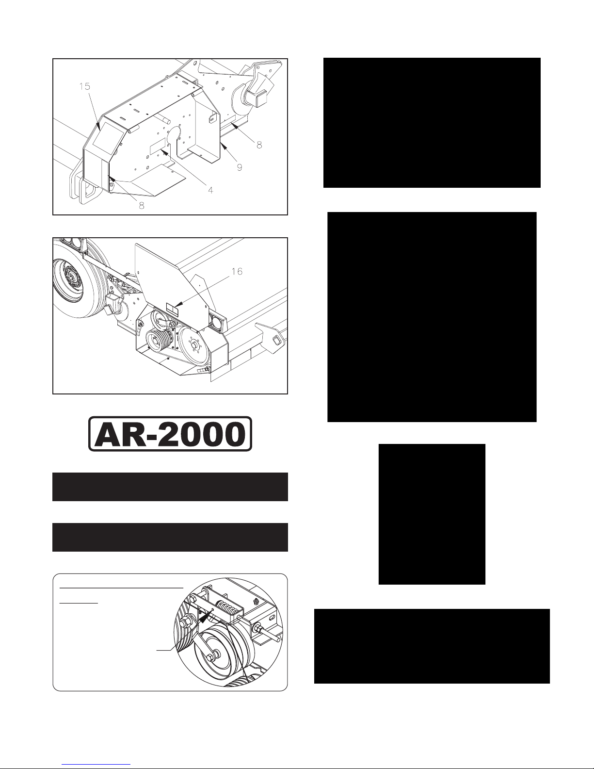
FIGURE 1 79202299 LOGO AR-2000
FIGURE 2 71505168 LOGO HINIKER
FIGURE 3 79202337 LOGO AR-2000
IMPORTANT: Maintain Belt Tension
Stop unit completely for maintenance.
No Rotation. Read Operators Manual.
Compress spring until
washer can be seen
through sight hole
PART NO. 79203548
FIGURE 4 79203548 IMPORTANT: MAINTAIN BELTS...
FIGURE 6 71504133 IMPORTANT: HITCH...
FIGURE 7 715-03174 IMPORTANT: LIFT...
FIGURE 8 850-001-285 TAPE YELLOW REFLECTOR
8 Decal Location
FIGURE 9 850-001-305 TAPE RED REFLECTOR
FIGURE 10 715-04132 CAUTION: READ MANUAL...
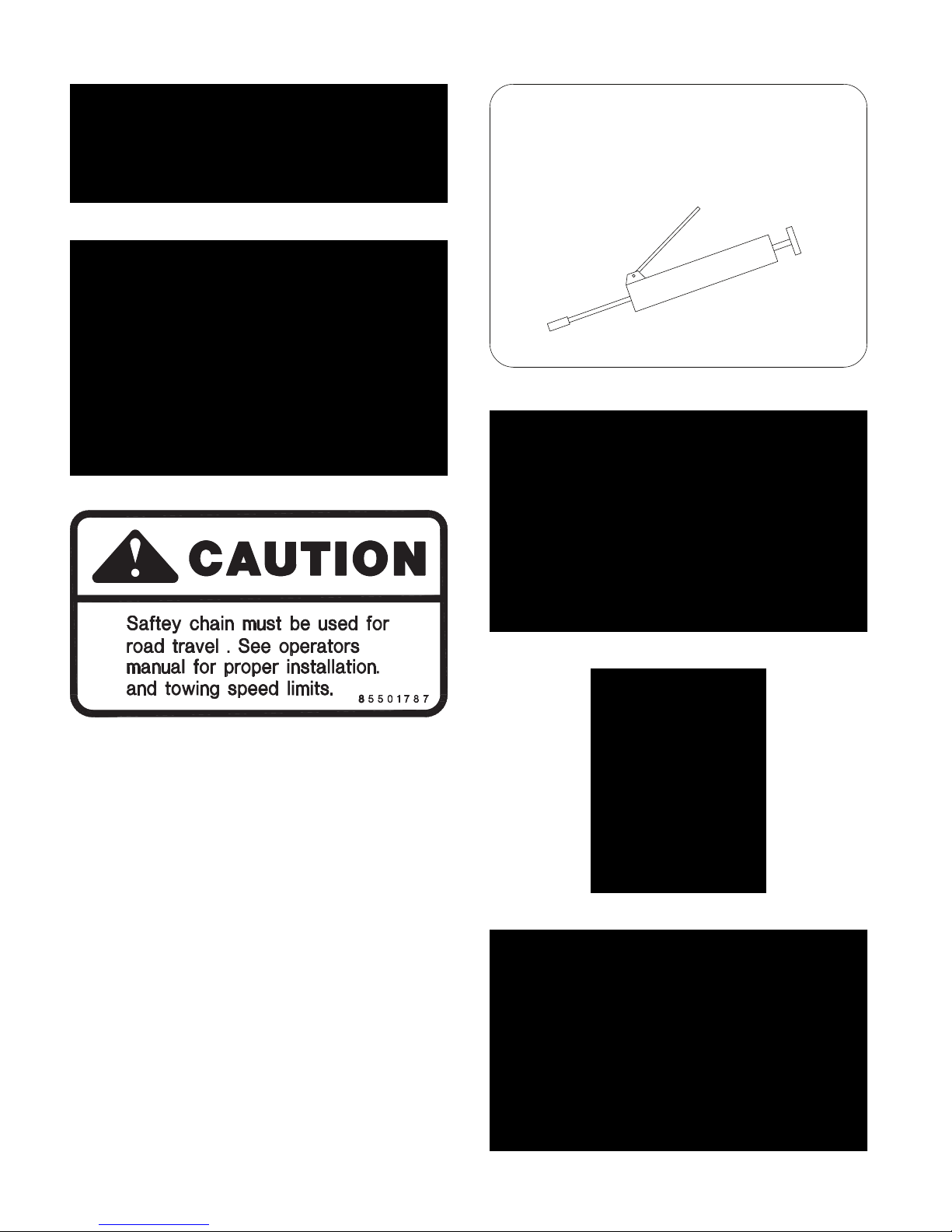
GREASE
FIGURE 13 79203259 GREASE:
FIGURE 11 85501787 CAUTION: SAFETY CHAIN...
FIGURE 12 71504129 CAUTION: 1000 RPM
FIGURE 14 71505169 WARNING: LOOK AND LISTEN...
FIGURE 15 71505171 WARNING: KEEP HANDS, ETC...
FIGURE 16 71505170 WARNING: DO NOT OPERATE...

Decal Location 9
FIGURE 17 520-03138 DANGER: ROTATING DRIVE...
FIGURE 18 520-03139 DANGER: SHIELD MISSING...
FIGURE 21 520-03138 WARNING: DO NOT EXCEED...
FIGURE 19 71504131 DANGER: KEEP FLIPPERS...
IMPORTANT
Maintain tires at 15-20 psi
on level land.
See operator's manual for
ridged operation.
FIGURE 20 71504136 IMPORTANT: MAINTAIN TIRES...
71504136

10 Field Preparation
10 Section
FIELD PREPARATION
WARNING: DEATH OR SERIOUS INJURY CAN RESULT. BEFORE FIELD
PREPARATION, READ SAFETY-GENERAL, BEFORE OPERATION, DURING OPERATION AND TOWING AT FRONT OF THIS
MANUAL.
TRACTOR-GENERAL
IMPORTANT: IT IS CRITICAL TO KNOW WHAT
SHREDDER CONFIGURATION IS INVOLVED
BEFORE TRACTOR HOOKUP. TRACTOR
MUST HAVE 1 3/4-20 SPLINE OUTPUT SHAFT.
Hiniker shredders are only available with a PTO
output option of: 1000 RPM 1 3/4”-20 spline
Part# 79202277
TITLE
Raise the shredder with hitch jack until the hitch
yoke corresponds with the tractor’s drawbar and
insert hitch pin. Always store the hitch jack (arrow 1) as shown in Photo DCP0603.
1
PHOTO NO. DCP0603
All units use ONLY CV (constant velocity) PTO’s.
These are identied by extended front yokes
separated by a large guide hub between them.
SHREDDER-TRAILING HITCH
Trailing shredders have an adjustable hitch
height adjustment (Item 1) to match various tractor drawbar heights. Refer to Photo 100-4282B.
1
PHOTO NO. 100-4282B
IMPORTANT: ALWAYS USE A 1” DIAMETER
HITCH PIN.
CAUTION: DEATH OR SERIOUS INJURY CAN RESULT. ALWAYS INSERT
THE HITCH PIN POINT DOWN WITH A
CROSS LOCKING PIN THROUGH ITS LOWER
END.
SHREDDER-PTO’s
IMPORTANT: IT IS CRITICAL TO KNOW WHAT
TRACTOR CONFIGURATION IS INVOLVED
BEFORE HOOKUP. THE PROPER SHREDDER
PTO MUST BE USED, OTHERWISE UNSATISFACTORY PERFORMANCE WILL RESULT.
TRACTOR MUST HAVE 1 3/4-20 SPLINE OUTPUT SHAFT.
All shredder PTO’s have similar sliding yoke
couplers at the tractor and gearbox ends. GEARBOX ENDS ARE IDENTIFIED BY AN OVERRUNNING CLUTCH (Item 1).
IMPORTANT: CORRECT TRAILING HITCH
DRAFT LINK LENGTH ADJUSTMENT CANNOT BE MADE UNTIL AFTER THE SHREDDER IS INITIALLY FIELDED.
Clean gearbox spline of any encrusted dirt or
grease and lightly oil it. Slide outer PTO collar
(Item 2) toward its adjacent yoke (Item 3) and
slide PTO over the gearbox spline. Reverse the
sliding collar to lock the assemblies together.

PHOTO NO. 2969A
NOTICE: TO FACILITATE PTO HOOK UPS, CHECK
TRACTOR SPLINE FOR BURRS, OR OTHER DAMAGE. IF SHREDDER’S LOCKING COLLAR IS DIFFICULT TO PROPERLY ENGAGE, CLEAN AND
LIGHTLY OIL SPLINE.
Field Preparation 11
DWG. NO. 71504129
DANGER: DEATH OR SERIOUS INJURY CAN RESULT. KEEP AWAY AND
KEEP OTHERS AWAY FROM AN OPERATING PTO. DO NOT OPERATE WITHOUT ALL SHIELDS IN PLACE. INSURE PTO
SHIELDS FREE WHEEL AND BOTH PTO’S
ENDS ARE SECURELY ATTACHED.
The tractor PTO spline engages similar to above.
Slide outer collar (Item 1) toward its adjacent yoke
(Item 2) and slide PTO over the tractor spline. Reverse the sliding collar to lock the assemblies together.
PHOTO NO. 2966A
WARNING: DEATH OR SERIOUS INJURY CAN RESULT. NEVER OPERATE
A SHREDDER UNLESS BOTH ENDS
OF THE PTO ARE PROPERLY LOCKED TO
THEIR INTENDED SPLINES.
Check the decal on gearbox shield to insure
proper tractor/shredder RPM matching.
IMPORTANT: NEVER TOW A TRAILING
SHREDDER UNLESS THE PTO IS PROPERLY HOOKED UP TO BOTH TRACTOR AND
SHREDDER. OTHERWISE, IT CAN BE DAMAGED. IF NECESSARY TO OTHERWISE TOW,
DETACH ENTIRE PTO ASSEMBLY (1) FROM
GEARBOX AND SECURE IT BEHIND A DRIVE
SHAFT SHIELD (2).
PHOTO NO. 3547
SHREDDER ROCKSHAFT & WHEELS
Toadjust therockshafteldwheelspacingthe
end transport wheels can be used. Insert tractor quick couplers to give machine a downward movement when tractor hydraulic lever is
pushed forward.

12 Field Preparation
DWG NO. 6668
To adjust wheel spacing on rear rock shaft wheels,
attach a tractor of adequate size to operate unit
totheeldhitch.Slideendtransporthitchoutand
pin in position (arrow 1). Attach jack to spud on
hitch. Using tractor hydraulics lower end transport
wheels(arrow2)andraiseeldwheels(arrow3).
Rotate locking channels (arrow 4) over end transport hydraulic cylinder shafts to prevent cylinder
contracting.
Once correct spacing is set up unlock end
transport cylinder locks. Lower eld wheels all
the way down. Raise end transport cylinders and
slide end transport hitch in and re-pin in position.
Store jack in its storage position.
1
PHOTO NO. 1000-4284A
Hydraulic cylinder control segments (arrow 1)
are provided to hold machine at desired cutting
height.
Loosen wheel bolt clamps and slide wheels into
correct dimensionsforeld operation.The correct spacing for 30” and 36” row and is provided
in the table below.
Dimns. 30” Rows 36” Rows
30 foot units
(outer) (1) 180” 180”
(inner) (2) 30” 36”
DWG NO. 6667
SHREDDER TIRES
Recommended tires are 9.5L x 15 8 ply
(implement) tires with 8” rims. The shredder
will perform better, especially under ridged
conditions, if tire pressures are kept no greater
than recommended. (If the shredder tends to
“yaw”, or climb ridged rows, decrease pressure
in the outside tires to the lower range cited and
recheck that tire centerlines are running in the
row middles.
SHREDDER-END TRANSPORT TOWING
Hiniker 30 Ft. shredders are designed for end
transport only down public roadways. Implement
lights (arrow 1) and SMV sign (arrow 2) are
standard equipment and mounted on rear of
machine.
For other row spacings, adjust the above settings accordingly. Torque up each wheel leg
clamping bolts by uniformly tightening the lower
boltsto a snug t.Then,torque, andre-torque
top bolts to 146-206 Ft/lbs.

Field Preparation 13
2
1
PHOTO NO. ARS048A
CAUTION: DEATH OR SERIOUS INJU-
RY CAN RESULT. WHEN TOWING ON
PUBLIC HIGHWAYS:
USE A TRACTOR OF SUFFICIENT SIZE, AND
WEIGHT, REQUIRED FOR FIELD OPERATION.
DO NOT TOW AT SPEEDS IN EXCESS OF 25
MPH (40 KMH).
USE A TOWING CHAIN BETWEEN TOWING
VEHICLE AND SHREDDER.
THE SMV’S REFLECTIVE SURFACE MUST
BE VISIBLE FROM THE REAR OF UNIT.
CHECK LOCAL REGULATIONS ON TOWING
WIDTH AND WARNING LIGHTS.
THE FRONT HITCH, PTO AND PTO HOLDER
MAY BE REMOVED TO REDUCE THE END
TRANSPORT WIDTH IF REQUIRED.
PHOTO NO. 3550
Check the lights to be sure they are connected prop-
erlysothatturnsignalashersoperatecorrectly.
Use a safety towing chain (Item 1) between the
shredder and towing vehicle. Hook chain around
bracket (Item 2) and pass forward through aftermarket clevis (Item 3). Fix chain’s forward end
(Item 4) to tractor.

14 Section
14 Operation
TITLE
OPERATION
WARNING: DEATH OR SERIOUS INJURY CAN RESULT. BEFORE OPER-
ATING, READ SAFETY-GENERAL,
BEFORE OPERATION, DURING OPERATING
AND TOWING AT FRONT OF THIS MANUAL.
GENERAL
DWG. NO. 71504131
IMPORTANT: FOR TRAILING HITCH END
TURNS ACROSS RIDGED ROWS, SLOW
FORWARD SPEED AND RAISE MACHINE
TO MINIMIZE EXCESSIVE BOUNCING AND
SCALPING.
CAUTION: DEATH OR SERIOUS INJURY CAN
RESULT. FOR TRAILING UNITS, SOME
TRACTOR MASTER PTO SHIELD’S
MAY CONTACT SHREDDER’S FRONT
PTO SHIELD ON TURNS. BE ALERT FOR
THIS AND MAXIMIZE TURNING RADII. REPLACE SHREDDER FRONT PTO SHIELD IF IT
BECOMES DAMAGED.
IMPORTANT: INITIALLY START SHREDDING
WITH UNIT SET SUBSTANTIALLY HIGHER
THAN THE RECOMMENDED MINIMUM KNIFE/
ROW CLEARANCE OF 3”.
Shred a short distance and check performance.
The higher knife/row clearance may not give satisfactory results; therefore, lower unit and check
again. Progressively lower unit until good results
are obtained. DO NOT OPERATE WITH LESS
THAN 3” KNIFE CLEARANCE TO HIGHEST
GROUND POINT WITHIN SHREDDED WIDTH.
DWG. NO. 71504132
Always operate tractor at standard 1000 RPM
PTO. Use transmission up, or down, shift to
vary forward speed. CONSISTENTLY OVERSPEEDING THE PTO WASTES FUEL AND AGGRAVATES KNIFE WEAR.
Avoid “jackrabbit” PTO engagement at full speed
because it overstresses the shredder’s driveline.
Engage PTO at slow speed and throttle up to
operating speed.
Insert quick couplers to give shredder a DOWNWARD movement when tractor hydraulic lever is
shoved FORWARD and vice versa.
Once optimum height is set, insert equal amount
of hydraulic cylinder stop segments over the
rods of the lift cylinders to hold machine at desired height.
IMPORTANT: “SCALPING” ROWS WASTES
FUEL AND RAPIDLY AGGRAVATES KNIFE
WEAR. THIS IS PARTICULARLY TRUE IN
ROCKY FIELDS. IF YOUR FIELD HAS PROTRUDING ROCKS, KEEP UNIT’S HEIGHT
SUFFICIENT FOR KNIVES TO CLEAR THEM.
STALK SHREDDERS ARE NOT INTENDED TO
BE USED AS A “ROCK PICKER”, OR A “ROTOTILLER”.
Operate the shredder approximately LEVEL.
That is, front (Item 1) of main frame should clear
ground about the same as the rear (Item 2).

Operation 15
CAUTION: DEATH OR SERIOUS
INJURY CAN RESULT. EXCESSIVE
FRONT FRAME/GROUND CLEARANCE
CAUSES MORE DEBRIS TO THROW
FORWARD UNDER THE TRASH SHIELDS.
NEVER STAND NEAR, AND AHEAD OF, A
RUNNING MACHINE.
DWG NO. 6869
TRAILING HITCH HEIGHT ADJUSTMENT
1. Position unit astraddle rows and insure
wheels are centered in row middles before
making any adjustments. Rotate
rockshaft/wheels until knives clear rows by
GREATER than 3”.
3. Shred a short distance, stop and check
stubble to insure knives are properly clearing rows and satisfactory performance is obtained. If necessary, reset rockshaft/wheels
and drawbar’s underneath draft link.
4. Ensure cylinder stop collars, are of equal
height on lift cylinders.
END TRANSPORT TOWING
The 30 Ft. AR shredder can only be towed down
public highways in end transport mode. Towing
theshredderineldmodedownpublichighways
will violate local regulations and is prohibited.
CAUTION: DEATH OR SERIOUS INJURY CAN RESULT. WHEN TOWING ON
PUBLIC HIGHWAYS:
USE A TRACTOR OF SUFFICIENT SIZE, AND
WEIGHT, REQUIRED FOR FIELD OPERATION.
DO NOT TOW AT SPEEDS IN EXCESS OF 25
MPH (40 KMH).
USE THE PROVIDED SAFETY TOWING
CHAIN BETWEEN TOWING VEHICLE AND
SHREDDER/WINDROWER.
1
PHOTO NO. 100-4277A
With unit attached to tractor, adjust turn-
buckle (arrow 1) to raise machine front up
or down to desired height.
2. Recheck knives/row clearance and readjust rockshaft/wheels, as well as draft link
length, if necessary.
USE THE SMV EMBLEM AS SPECIFIED AND
STORE PTO SHAFT IN PTO HOLDER.
CHECK LOCAL REGULATIONS ON TOWING
WIDTH AND WARNING LIGHTS.
DWG NO. 6868
To put the machine in end transport. With tractor
attachedtotheeldhitchSlideoutendtransport
tongue (arrow 1) and pin in position.

16 Operation
Rotate jack into position. Lower end transport
wheels all theway down(arrow 2). Raise eld
wheels all the way up (arrow 3). Rotate hydraulic
cylinder channel locks (arrow 4) into position to
hold cylinders in the fully extended position. Using jack raise front end of tractor until the cast
hitch on shredder comes off the draw bar of the
tractor.
DWG NO. 6870
Disconnect hydraulic lines and store in hydraulic tip holder (arrow 5). Flip up PTO holder (arrow 6). Disconnect PTO and lay in PTO holder.
Raise or lower end transport hitch so it can be
attached to tractor drawbar. Attach tractor of suf-
cientsizeforoperationtoendtransporttongue.
Storejackoneldhitchstoragelocation.
1
2
PHOTO NO. 3550B
Attach safety chain on end transport hitch to
tractor.
Insert electrical connector into tractor. Verify
warning lights and turn indicators all work correctly. Verify SMV sign is visible from rear of machine.
STORAGE
CAUTION: DEATH OR SERIOUS
INJURY CAN RESULT. DISENGAGE
PTO, STOP TRACTOR ENGINE,
SET BRAKES, REMOVE KEY AND ALLOW
EQUIPMENT TO COME TO A COMPLETE
STOP BEFORE:
DWG NO. 6871
Wrap safety Chain around hitch tube and pass
through the large chain end loop and welded on
c-channel.
CLEANING, UNCLOGGING, LUBRICATING,
INSPECTING, OR OTHERWISE SERVICING,
ANY PART OF THIS EQUIPMENT.
The following will insure equipment is in top
operating condition at start of next season.
1. Open end shields and thoroughly clean
out dirt and trash. Clean out any other
trash hanging on unit. Check drive shaft
and gearbox bearing seals for trash
entanglement.
2. Back off backwrap belt idlers to relax tension
on “V” belts. Inspect belts for wear.
3. Clean debris from PTO ends and insure
safety shield freely rotates.

4. Relube machine and check gearbox lube
level.
5. Clean rust off exposed surfaces and repaint
any surface requiring it. Also check for any
loose hardware.
6. Inspect both rotor assemblies for lost,
broken, or worn out knives. Replace
these as required. Also, replace any other
deteriorated parts, especially decals and
reectors.
Operation 17

18 Section
18 Lubrication
LUBRICATION
TITLE
WARNING: DEATH OR SERIOUS INJURY CAN RESULT. BEFORE LUBRICATING, READ SAFETY-GENERAL AND
SERVICE AT FRONT OF THIS MANUAL.
CAUTION: DEATH OR SERIOUS INJURY CAN RESULT. DISENGAGE PTO,
STOP TRACTOR ENGINE, REMOVE
KEY AND ALLOW EQUIPMENT TO COME TO
A COMPLETE STOP BEFORE: CLEANING,
UNCLOGGING, LUBRICATING, INSPECTING,
OR OTHERWISE SERVICING, ANY PART OF
THIS EQUIPMENT. SECURELY BLOCK UNIT
BEFORE SERVICING TO PREVENT UNEXPECTED FALLING.
HINIKER shredders have been factory checked
and lubricated. However, re-check and relubri-
cateaunitpriortorsteldoperation.
Lubrication Chart
Ref.
No. Description Interval
1. Front Cross & Bearing Daily
2. Front Shield Bearing Daily
3. Sliding Tube Daily
4. Rear Shield Bearing Daily
5. Rear Cross & Bearing Daily
6. Overrunning Clutch Daily
7. Front Shield Bearing Daily
8. CV Cross Daily
9. CV Cone Shield & Bearing Daily
10. Front Cross & Bearing Daily
Shredders operate in an extremely dirty (ne
dust) environment. Proper maintenance attention to the anti-friction bearings will save money!
IMPORTANT: WIPE ALL ZERKS AND GUN
TIPS BEFORE LUBRICATING.
IMPORTANT: WHEN LUBRICATING BEARINGS ADHERE TO 1 PUMP PER FITTING ON
A DAILY INTERVAL.
When lubricating, couplers, pivots, and PTO lubricate until you see grease. Items (8 & 15) CV
double yoke needs 15 to 20 pumps.
IMPORTANT: INNER ROTOR COUPLER (ITEM
29) NEEDS 20-25 PUMPS DAILY FOR PROPER OPERATION.
Replace anydamaged ttings andusea good
grade of lithium base grease.
Gearbox should be checked at least seasonally.
After300hoursoperation,drainandrell.
11. End Transport Pivot Daily
12. Overrunning Clutch Daily
13. Rear Cross & Bearing Daily
14. Rear Shield Bearing Daily
15. CV Flange (15-20 Pumps) Daily
16. Line Shaft Coupler (15-20 Pumps) Daily
17. Outer Rotor Bearing Daily
18. Rockshaft Bearing Weekly
19. Center Bearings Daily
20. Wheel Hub Weekly
21. Ratchet Jack
22. Gearbox Drain
23. Center Rotor Bearings Daily
24. Outer Lineshaft Bearing Daily
25. Mid Lineshaft Bearing Daily
26. Idler Pivot Weekly
Seasonal
300 Hours
A 1000 rpm gearbox is checked by measuring
3 7/8” to 4” depth to lube level below ll hole
thread top or use check plug at rear. Clean plug
before removing. Use a.P.I. 80W90 synthetic extreme pressure lubricant.
27. Gearbox Breather
28. Gearbox Oil Level Check Plug
29. Rotor Coupler (20-25 Pumps)
-----------
----------Daily

11
Lubrication 19
PHOTO NO. 2964
PHOTO NO. 2968B
PHOTO NO. 100-1334
14
13
12
PHOTO NO. DCP0569
15
8
7
8
PHOTO NO. DCP0560
7
10
9
PHOTO NO. DCP0571

20 Lubrication
DWG NO. 6877
DWG NO. 6878
PHOTO NO. 2976
DWG NO. 6872
DWG NO. 6876
DWG NO. 6875

25
Lubrication 21
29
19
PHOTO NO. 100-4281A
DWG NO. 6873
27
PHOTO NO. DSCN4609A
PHOTO NO. DCP0647
28

22 Section
22 Trouble Shooting
TROUBLE SHOOTING
TITLE
CONDITION POSSIBLE CAUSE CORRECTION
Poor shredding. 1. Missing, or broken knives. 1. Inspect and replace.
See SERVICE section.
2. Knives worn out. 2. Same as above.
3. Under speed PTO. 3. Check tractor for 1000 PTO RPM.
4. Slipping belts. 4. Check belts backwrap idler adjustment.
See SERVICE Section
5. Worn out belts. 5. Inspect belts for wear or mismatching.
Replace only in banded sets.
6. Shredder bouncing. 6. Deate tires to 15-20 psi. Slow down
ground speed.
7. Operating too high. 7. Decrease knives operating height to
approximately 3” above rows.
8. Excessive ground speed. 8. Slowdown.
Excessive row knife wear. 1. Operating too low. 1. Raise knives operating height to
approximately 3” above rows.
Excessive knife stone damage 1. Running too low. 1. Raise knives operating height to
approximately 3” above rows, or to clear
rocks.
Entire shredder crosswise “yawing”. 1. Wheel not exactly centered on middles. 1. Readjust wheel spacings.
2. Different tire sizes on same unit. 2. Correct.
Excessive shredder vibration. 1. Missing or broken knives. 1. Inspect and replace.
See SERVICE section.
2. Rock damaged rotor. 2. Replace.
3. Worn or loose rotor bearings. 3. Inspect and maintain.
See SERVICE section.
4. Loose or misaligned end sheaves. 4. Inspect and maintain.
See SERVICE section.
5. Deteriorated belts. 5. Replace belts.
6. High tire air pressure. 6. Bleed to 15-20 PSI.
Too rapid belt wear. 1. Belts too loose or too tight. 1. Backwrap idler tension not properly
maintained. See SERVICE section.
Crossways tilted operation. 1. Unequalized ratchet jacks or hydraulic
Excessive power required for available
tractor.
1. Equalize ratchet jacks or hydraulic cylinder
cylinder stops.
1. Cutting to low. 1. Raise knives operating height to
2. Excessive ground speed. 2. Slow Down.
stops.
approximately 3” above rows.

TITLE
SERVICE
Section 23
Service 23
WARNING: DEATH OR SERIOUS INJURY CAN RESULT. BEFORE SER-
VICING, READ SAFETY-GENERAL,
BEFORE OPERATION, DURING OPERATION
AND SERVICE AT FRONT OF THIS MANUAL.
CAUTION: DEATH OR SERIOUS IN-
JURY CAN RESULT. DISENGAGE
PTO, STOP TRACTOR ENGINE, SET
BRAKES, REMOVE KEY AND ALLOW EQUIPMENT TO COME TO A COMPLETE STOP BEFORE:
CLEANING, UNCLOGGING, LUBRICATING,
INSPECTING, OR OTHERWISE SERVICING,
ANY PART OF THIS EQUIPMENT.
DO NOT SERVICE OR OTHERWISE HANDLE
A MACHINE, IN A RAISED POSITION UNLESS
IT IS SECURELY BLOCKED AGAINST UNEXPECTED FALLING.
DO NOT SERVICE END DRIVE BELTS WHEN
TRACTOR IS RUNNING.
REPLACE ALL SHIELDS REMOVED FOR
SERVICE BEFORE OPERATING THIS EQUIPMENT.
HARDWARE
Shredders operate in an inherently vibratory environment. Discipline yourself to regularly check
suspect bolt torques and lost, warn out, or broken parts. Replace these promptly.
HINIKER shredders are EQUIPPED ONLY
WITH GRADE 5 BOLTS (3 marks on heads) and
retained with TYPE B or F LOCKNUTS (except
on wheel legs, sheaves, backwrap idler inside
nut, and the gearbox which have lock washers).
Type B locknuts are PLAIN hex. Type F locknuts
are FLANGED hex.
IMPORTANT: DO NOT REPLACE HARDWARE
WITH LOWER GRADE ITEMS. EXCEPT ON
SHEAVES, ALL BOLT TORQUE VALUES ARE
FOR GRADE 5. HARDWARE OVER, OR UNDER, TORQUING, CAN RESULT IN UNSATISFACTORY DURABILITY.
Diameter Ft/lbs. N/m.
5/16” 13-18 17-25
3/8” 23-33 31-44
7/16” 38-54 51-73
1/2” 58-82 79-112
5/8” 117-165 158-223
3/4” 206-292 280-396
1” 500-708 678-960
GRADE 5 TYPE B & F LOCKNUT
TORQUE VALUES
Diameter Ft/lbs. N/m.
3/8” 29-41 39-56
1/2” 73-103 99-140
5/8” 146-206 198-279
* applications without locknuts
GRADE 5 BOLT TORQUE VALUES*
It is a good idea to recheck critical bolt torque
valuesaftertherst2or3hoursofoperation.
KNIVES
HINIKER shredder rotors are factory dynamically balanced.
WARNING: DEATH OR SERIOUS INJURY CAN RESULT. SHOULD ABNOR-
MAL ROTOR VIBRATION OCCUR AT
ANY TIME, IMMEDIATELY DISENGAGE PTO,
STOP TRACTOR ENGINE, SET BRAKES,
REMOVE KEY AND DETERMINE/CORRECT
CAUSE BEFORE PROCEEDING.

24 Service
Periodically inspect rotor assemblies for broken
or missing knives. Immediately replace those
so indicated because they will cause the rotor
to run out of balance. Partially worn out SIDE
SLICER knives may be removed and reversed
to give a fresher cutting edge. HINIKER knives
are marketed singularly; however,
IMPORTANT: REPLACE KNIVES IN OPPOSITE (180° APART) SETS. ALSO, REPLACE
CORRESPONDING IDENTICAL KNIVES AT
OTHER END OF SAME ROTOR HALF.
Shredders are factory shipped with SIDE SLICER knives, per Photo 1575A.
Rotate the knives so that the edge of the side
slicer knives that is not worn is facing in the
direction of travel. Put the knives and bushing
back between the same ears that they came
from on the shredder rotor. Secure them by
torquing the 5/8 x 2 3/4” Gr. 8 bolt and lock nut
to 95 -110 lb. ft.
To replace side slicer knives loosen the 5/8” x
2 3/4” Gr. 8 bolt and lock nut.
Remove the bolt from the ears on the shredder rotor and pull out the two side slicer knives
and the bushing. See Photo DCP0594.
Examine the side slicer knives (Item 1), bushing (Item 2), 5/8 x 2 3/4” Gr. 8 bolt (Item 3) and
the 5/8” lock nut (Item 4). Replace the worn
knives and the bushings if worn or cracked.
Always replace knives in opposite (180 degree apart) sets. Also, replace corresponding
knives at the other end of the same rotor. This
will help to keep the rotors balanced. See Photo DCP0597.
PHOTO NO. 1575A
Shredder side slicer knife Service
To rotate side slicer knives loosen the 5/8” x 2 3/4”
Gr. 8 bolt and lock nut. Remove the bolt from the
ears on the shredder rotor and pull out the two
side slicer knives and the bushing. See Photo
DCP0594.
1
PHOTO NO. DCP0597
4
2
3
Knives hardware should be torqued to 95-110 ft/
lbs (128-149 N/m).
PHOTO NO. DCP0594

Service 25
BELTS
HINIKER shredders are EQUIPPED ONLY WITH
PREMIUM GRADE BANDED BELTS. Do not replace these with “garden variety” belts because
their power transmission capability, and durability, will be degraded.
NOTICE: ADEQUATE TENSION IS NECESSARY FOR FULL POWER TRANSMISSION
AND SATISFACTORY BELT PERFORMANCE.
1. Belt tension is obtained by following instructions on decal located on endplates inside
each end shield.
IMPORTANT: Maintain Belt Tension
Stop unit completely for maintenance.
No Rotation. Read Operators Manual.
Compress spring until
washer can be seen
through sight hole
OUTER ROTOR BEARINGS
All rotor bearings are flange mounted and piloted. They have no eccentric locking collars and
are loosened from their shafts by removing (2)
3/8” Allen set screws from their inner races. Because of high vibration associated with shredders, these set screws are retained with an anaerobic threadlock (eg. Locktite 242 (blue) or
Perma-Lok HM 118 (red). Important: Use only
grade 5 bolts and type B lock nuts with thread
lock when replacing.
PART NO. 79203548
DWG. NO. 3543
2. Recheck initial belt tension after rst hour
and rstday of operation. Loose beltscan
“glaze” and contribute to slippage. DO NOT
USE BELT DRESSING ON “V” BELTS. This
will aggravate poor belt function.
If evidence exists of belts overheating and/or
excessive side wrapper wear, check sheave
alignment. See Photo DCP0618, page 28.
3. Replacement belts should only be ordered
by specic HINIKERpart number.The correct belt part numbers are:
(6/5VL794 banded belt) Part No. 79203528
4. Install new belts as follows:
a. Loosen double nut on outside of drive shield
to remove tension on belt idler.
b. Remove old belts.
c. Roll (DO NOT PRY) the new belt into the
pulley grooves working back and forth between the large and small pulley.
DWG NO. 6879
2
3
4
PHOTO NO. 100-1311A
1. Loosen spring tension (Item 1) and remove
belt (Item 2) and driveN sheave (Item 3).
See Photo 110-1311A.
CAUTION: DEATH OR SERIOUS INJURY CAN RESULT. ROTORS ARE
HEAVY AND SUBJECT TO UNEXPECTED MOVEMENT. SECURELY UNDERNEATH
BLOCK ROTOR END BEING SERVICED
AGAINST DROPPING OR SHIFTING BEFORE
THE END BEARING IS REMOVED FROM ITS
PILOT HOLE.

26 Service
2. Remove (4) 3/8” bolts (Item 4) and the
(2) inside anti-wrap shields. This allows
wrench access to the bearing mounting bolt
heads. See Photo 100-1311A and Photo
DCP0659B.
3. Loosen outer end zerk hex nut of lube
tube and detach tube from bearing.
Circumferentially polish shaft (Item 5).
Remove (3) 3/8 bolts (Item 6) securing the
bearing support plate to the shredder end
panel. See Photo DCP0659B.
4. Remove (2) 3/8” Allen set screws from the
inner race of the outer rotor bearing which
are factory retained with anaerobic thread
lock Perma-Lok HM118 (red) or Locktite 242
(blue).
8
4
4
Washer Part Number
1/16” Thick 79202329
1/8” Thick 79202328
7. After the washers have been checked, torque
bearing mounting bolts and Allen set screws.
Torque the Allen screws once, loosen and
torque a second time. Reinstall anti-wrap
shields and torque support plate bolts.
Commercial anaerobic threadlocks have
installation instructions, and SAFETY CAUTIONS, on their containers. These should
be adhered to.
8. Reinstall and realign previously removed
sheave and belt.
INNER ROTOR BEARINGS
1. To remove the rotor the shredder must be
turned upside down.
7
6
PHOTO NO. DCP0659B
5. Remove (4) 1/2” locknuts (Item 7) which are
factory retained with anaerobic threadlock
(eg. Lock-tite 242 (blue) or Perma-Lok HM
118 (red). Modestly pry plate (Item 8) outward to start bearing off shaft.
6. A varying quantity of 2 3/16” nominal. I.D.
washers are factory installed between the
inner end of bearing and the shoulder on
shaft. Because replacement bearings vary
in axial dimensions, care must be exercised
to FULLY WASHER THE SPACE BETWEEN
THE BEARING AND SHAFT SHOULDER.
Reinstall plate (Item 8) and bearing by temporarily snugging up (2) each of their bolts
(without anti-wrap shields). Visually check
above cited washers to insure no looseness, or substantial axial preload, exists. 2
3/16 inch nominal I.D. washers are available
as part numbers:
6
5
2. Raise front and securely block front corners.
Remove SMV, PTO, and trailing hitch.
3. Remove belt and sheave or rotor. Fully retract cylinder(s). Loosen both inner and outer
bearing’s lube tube zerk nuts and detach lube
tubes from their supports. Remove lights and
light brackets.
4. Temporarily insure end panel shields are
latched shut. Reinstall hitch pins and their
cotters.
WARNING: DEATH OR SERIOUS INJURY CAN RESULT. DO NOT ATTEMPT
TO REMOVE A ROTOR FROM UNDER
NEATH A SHREDDER IN ITS OPERATING POSITION.
NEVER ATTEMPT TO REMOVE A ROTOR
WITH THE UNIT UPENDED IN A VERTICAL
POSITION.
WARNING: DEATH OR SERIOUS IN-
JURY CAN RESULT. USE HOISTING
EQUIPMENT CAPABLE OF SAFELY
HANDLING NO LESS THAN 4 TON (8000#).

Service 27
WARNING: DEATH OR SERIOUS INJURY CAN RESULT. CLEAR PEOPLE
FROM WORK AREA WHEN TIPPING
SHREDDER OVER. DO NOT WORK ON SOFT,
OR UNEVEN, GROUND. LIFT ONLY FROM
MAIN FRAME 1 INCH DIAMETER HITCH PINS.
5. Securely block rear (Item 1) of each wheel
and approach shredder from REAR. Use a
chain sling (Item 2) approximately 5’ long
on each run. Fix EACH sling chain hook
SECURELY around both 1” diameter hitch
pins (Item 3) where shown by decal (Item 4).
Lift unit until wheels are about to clear the
ground.
2
4
3
Unless this bearing is also being serviced, it
is not necessary to remove it from the rotor
at this time.
8. Remove center anti-wrap shields. This allows access, through the rotor’s inner end
notches to bearing’s inner race Allen set
screws. Detach shield and lube tube.
9. Loosen (2) 3/8” Allen set screws (Item 1)
from center bearing (Item 2). These are retained with anaerobic threadlock (eg. Locktite 242 (blue) or Perma-lok HM 118 (red).
See Photo DCP0591.
1
2
1
PHOTO NO. 2990B
6. Move wheel blocks previously installed to
opposite side of wheels (Item 1). Swing unit
rearward and overcenter, then slowly lower the unit to the ground. Open end shield
(Item 3) and detach bottom enclosure plate
(Item 4).
PHOTO NO. DCP0591
Commercial anaerobic threadlocks have installation instructions, and SAFETY CAUTIONS, on
their containers. These should be adhered to.
10. Attach chain sling around rotor. Outer end
of rotor is lifted above frame to obtain clearance.
Axially pry rotor free of its inner bearing and
swing it clear of working area. NOTE: Carefully lift both split rotors together on units
with four rotors. Sling should be from center
of rotors to reduce stress on coupling.
7. Loosen outer bearing from its mounting as
shown in Photo DCP0659B on page 26.
PHOTO NO. 3014

28 Service
Check that all previously removed and/or
loosened parts are properly reinstalled. Remove hoist and reverse above tipping procedure to return the unit to operating position
and reinstall previously removed hitch, etc.
SHEAVES ALIGNMENT
It is unnecessary to realign sheaves unless they
have been damaged, removed or loosened. Do
not realign sheaves unless they are more than +
or - 1/16” misaligned. See Photo DCP0618.
DWG. NO. 6384
11. Circumferentially polish rotor center stub
shaft and reinstall it in replaced bearing. Insure stub shaft shoulder is against bearing
inner race. Torque (2) Allen set screws once,
loosen and torque them a second time.
IMPORTANT: WHENEVER THESE LOCK
NUTS/BOLTS ARE DISCARDED, ONLY
GRADE 5 BOLTS AND TYPE B LOCKNUTS SHOULD BE REINSTALLED. THE
ABOVE CITED (OR SIMILAR) ANAEROBIC
THREADLOCK SHOULD BE USED IN REASSEMBLY OF BEARING MOUNTING BOLTS
AND ALLEN SET SCREWS. TORQUE ALL
BEARING MOUNTING BOLTS TO 58-82 Ft/
lbs. (79-112 N/m.).
12. Temporarily reinstall (4) 3/8” bolts through
outer bearing mounting plate and snug them
up. Do not reinstall outer anti-wrap shields
at this time. Check varying quantity of 2
3/16” nominal I.D. washers between outer
bearing’s inner race and shoulder of rotor
shaft. If these are axially SNUG WITH NO
PRE-LOAD, proceed to completely reinstall
outer bearing and anti-wrap shields.
1
2
3
PHOTO NO. DCP0618
1. It is generally best to align driveR (Item 1)
to driveN sheave (Item 2); thus, only (1)
sheave need be loosened.
2. Determine misalignment by placing a steel
straight edge (Item 3) across sheaves as
shown. Move sheave in or out to align.
SHEAVES REMOVAL/INSTALLATION
1. Loosen belt’s backwrap idler and remove
belts.
13. If washers are not as stated above, it will
be necessary to remove outer bearing. See
Photo DCP0659B, page 26 and add, or subtract, washers. 2 3/16” nominal I.D. washers
are available as part numbers:
Washer Part Number
1/16” Thick 79202329
1/8” Thick 79202328
1
5
3
4
6
PHOTO NO. 100-1311B
2

Service 29
2. Loosen and remove bolts from (3) UNTHREADED holes (Item 1).
3. Insert these bolts in the (3) THREADED
holes (Item 2). Start with the bolt furthest
from the inner bushing’s slot (Item 3) and
gradually alternately torque bolts in a uniform pattern. Continue torquing in small increments until the tapered surfaces disengage. The same procedure is used if driveN
sheave (Item 4) is to be removed.
NOTICE: EXCESSIVE AND/OR UNEQUAL
BOLT TORQUES CAN BREAK THE INNER
BUSHING’S FLANGE.
4. The inner bushings are retained with 3/8” Allen set screws (Item 1) over their keyways
(Item 2). Remove the set screw to enable
removal of the inner bushing.
7. Align (3) UNTHREADED bolt holes with
THREADED bolt holes in mating sheave
or bushing. Inset bolts and lockwashers
in these UNTHREADED holes and tighten
about (2) turns each.
8. Alternately torque these bolts , in a uniform
pattern, until the tapers are seated (approximately 1/2 bolt torque). Check for sheave
alignment and possible wobble. Correct if
necessary.
IMPORTANT: SHEAVE BOLTS ARE ONLY
TORQUED TO VALUES:
Dia. Ft/lbs. N/m.
3/8” 30 41
1/2” 75 102
9. Continue bolt torquing until above values occur, or NO LESS THAN 1/8” HUB FLANGE
TO SHEAVE CLEARANCE EXISTS. There
will always be a gap in the inner bushing
hub when proper procedure is followed.
1
2
PHOTO NO. DCP0656
5. For installation, insure the tapered mating
surfaces of the inner bushing (Item 5) and
sheave (Item 6) are free of dirt, paint, rust,
metal chips and LUBRICANT.
IMPORTANT: DO NOT USE LUBRICANTS,
ANTISEIZE, AND/OR EXCESSIVE BOLT
TORQUES WHEN ASSEMBLING Q.D.
SHEAVES. THESE CAN BREAK THE ASSEMBLY.
6. Insure woodruff key is in place before sliding inner bushing on shaft. Align (in/out) the
Allen set screw hole of the bushing being
installed with existing witness marks on its
shaft and torque the set screw.
NOTICE: INDIVIDUAL BOLT TORQUES
SHOULD BE ACHIEVED NO MORE THAN (2)
TIMES IN THE TIGHTENING CYCLE.
10. Reinstall belts and reposition backwrap
idler.
DRIVE SHAFTS BEARINGS
The front drive shafts bearings have set screw
lock collars. To loosen these, loosen 3/8” Allen
set screw therein.
Servicing these bearings requires removing
the driven sheave, See page 28-29 and extract
the drive shaft. Paint must be polished off drive
shaft to permit stripping it through the bearings.
WHEEL BEARINGS & SEALS
HINIKER shredders are equipped with O.D. riding triplex (3 labyrinths) seals. They also have
a replaceable seal riding ring (Item 6) and zerk
relube in the hub. This system is highly effective
when properly installed and maintained. See
Photo 3011 on page 30.

30 Service
IMPORTANT: WHEEL SEAL AND RIDING RING
MUST BE INSTALLED IN THE RIGHT DIRECTION, PROPERLY PRE LUBED AND THE HUB
FULLY PACKED WITH LUBE. IGNORING PROCEDURES BELOW WILL RESULT IN PREMATURE CONTAMINATION AND FAILURE.
1. Remove hub, inboard bearing cone (Item
1), outboard bearing cone (Item 2) and seal
(Item 3) from spindle. Thoroughly clean
hub’s interior grease cavity, both bearing
cups (Item 4), cones (Item 1 and Item 2),
hub cap (Item 5) and pre load hardware.
PHOTO NO. 3011
2. Discard old seal (Item 3) and inspect bearings for deterioration. Replace both cups
and cones if necessary. Generally, seal riding ring (Item 6) should be replaced when
doing wheel hub maintenance.
IMPORTANT: PRESS SEAL RIDING RING
INTO HUB WITH INTERIOR EDGE FLANGE
TOWARD INBOARD BEARING CUP. MANUALLY WORK LUBE INWARD BETWEEN (3)
SEAL LABYRINTHS BEFORE INSTALLING.
CAREFULLY START NEW SEAL (ITEM 3)
ONTO SPINDLE WITH BEARING CONE (ITEM
1) WHICH CAN BE SEATED WITH A 3/16”
PUNCH OR 1 1/2” I.D. DRIVER. INSURE SEAL
IS NOT CROOKED AND IS INSTALLED WITH
ITS SHARP EDGED INSIDE FLANGE TOWARD THE OUTBOARD SPINDLE END. THE
OPPOSITE (SMOOTH) SEAL FACE IS USUALLY MARKED “OUTSIDE”. THIS MUST ALWAYS FACE THE SPINDLE’S INBOARD END,
OTHERWISE THE SEAL WILL NOT FUNCTION CORRECTLY.
GEARBOX
All Hiniker 1000 RPM shredders are equipped
with a common 1.00:1.00 ratio gearbox. Refer to
Photo 3008A and DWG. 6088 on page 32.
PHOTO NO. 3008A
Gearbox can best be worked on as follows:
1. Detach tractor PTO at gearbox input spline.
3. Install hub, outboard bearing cone (Item 2),
end washer and adjusting nut. Adjust nut
with a HAND WRENCH ONLY. Tighten until seal is seated and bearings substantially
drag, then back nut off 1/6 turn to insert and
spread cotter.
4. Use zerk to fully lube hub cavity and bearings, while rotating hub, and until lube
emerges through outboard bearing. Pack
hub cap (Item 5) with lube and drive it home.
Continue lubing hub until lube emerges
around seal’s outside diameter.
2. Remove the left cross drive shaft shield.
Loosen and remove left outboard drive shaft
bearingangebolts.Thiscanbedonewithout removing the driveR sheave by slacking
off the backwrap idler and removing belts.
This permits sliding the entire left drive shaft
assembly leftward; thus, allowing room to
slide the gearbox loose from its R.H. spline
coupling.
3. Remove the (2) right 3/8” bolts nearest the
gearbox holding the right cross shaft shield.

Service 31
4. Remove the top (4) 1/2” bolts holding the
gearbox/PTO input shield and remove this
shield.
5. Remove the bottom (4) 1/2” gearbox mounting bolts and slide the gearbox leftward suf-
cient to uncouple it from its right splined
coupler. Then slide the gearbox forward to
remove it for placing on a workbench.
6. Remove the gearbox drain plug and discard
the lube.
The gearbox has no shims because preload and
backlash are factory set. To service this box proceed as follows:
1. Remove (12) 3/8” socket head bolts (Item
1) holding the 2 halves together. Tap input
shaft (Item 2) with a soft hammer, while
holding the output shaft (Item 3) off the work
table. Be careful to not damage the case’s
mating surfaces by prying them apart.
5. Whenever shafts are disassembled, make
sure the same thickness snap ring (Item 5)
are used to maintain backlash and preload.
There is (1) external snap ring used. For reassembly, capture bearings and seals in appropriate machined areas. Tap gently with
a soft hammer to seat, being careful to not
damage seals.
6. After both shafts have been reseated, apply
anaerobic sealant (eg. Locktite 518 (red) or
Perma-Lok HH 190 (dark purple) or Permatex silicone sealant 765-1344/1485) to
housing top half and reseat it on bottom
half. Apply pressure, or tap lightly, until top
halfisrmlyinplace.Replace,andretorque
the (12) previously removed socket head
bolts.
Commercial anaerobic sealants have installation and SAFETY CAUTIONS on their containers. These should be adhered to.
2. The input and output shafts and gears are
precision tted. Do not separate them by
prying on an individual set. Lift them apart
together.
3. Remove old anaerobic sealant and complete necessary maintenance. Whenever a
gearbox is opened, all 3 oil seals (Item 4)
should be replaced. Lube the seal’s inside
diameters before reinstalling and insure
their spring garters are toward the gearbox’s
inside.
4. Clean gearbox of all dirt and metal particles.
Inspect all removed parts for wear. Replace
any bearing showing signs of pitting, inability to rotate freely and discoloration. Clean
any bearings to be reused and coat with
gear lube. Replace gears showing pitting,
breaks or de-formation. Replace input and
through shafts having spline wear or deformation.

32 Service
1000 RPM GEARBOX ASSEMBLY
REF.
NO.
1
400-17205
2
400-17206
3
50106488
4
50106489
5
601-05002
6
601-02075
7
601-05001
8
601-03003
PART
NUMBER
DESCRIPTION QTY.
Casting (Tapped Holes)
Casting (Thru Holes)
Pinion Shaft/Gear
Cross Shaft/Gear
Bearing Cup (Large)
Bearing Cone (Large)
Bearing Cup (Small)
Bearing Cone (Small)
DWG. NO. 6088Gearbox Assembly 51700216
REF.
NO.
1
1
1
1
1
1
3
2
9
650-06056
10
702-05093
11
950-011-032
12
203-51156
13
203-51074
14
203-50308
15
601-02001
16
79201412
PART
NUMBER
DESCRIPTION QTY.
Seal (1 3/4 Shaft)
Retaining Ring (1 3/4 Shaft)
Socket Head Cap Screw 3/8-16 x 2 1/4
Plug, 1/2 NPT Sock Head Hex
Bushing, 1/2 NPT - 1/8 NPT
Pressure Relief
Bearing Cone 625580
Plain Plug 1/4 NPT #200300
3
1
12
1
1
1
1
1

TITLE
ASSEMBLY
Service 33
Assembly 33
Section 33
WARNING: DEATH OR SERIOUS INJURY CAN RESULT. BEFORE ASSEMBLING, READ SAFETY-GENERAL AT
FRONT OF THIS MANUAL.
OFFLOADING
Warning: Death Or Serious Injury Can
Result. Use Equipment Capable Of
Safely Handling No Less Than: 4 Ton
(8000#).
WARNING: DEATH OR SERIOUS INJURY CAN RESULT. CLEAR PEOPLE
FROM CARRIER AND OFFLOADING
AREA. DO NOT OFFLOAD ON SOFT, OR UNEVEN GROUND. AVOID HIGH WORK SPEEDS
AND “JACKRABBIT” MANEUVERING.
HINIKER shredders are shipped vertical with
self contained storage and handling dunnage.
They may be off-loaded with a forklift or an overhead chain sling.
For forklift off-loading, (2) fork pockets (Item 1),
spaced 32” apart, are provided. The forklift may
approach the shredder from either the knives, or
hood, face. Set forks centerlines 32” apart and
position forklift as close as possible to shipping
package. Lift off carrier and deposit on a rm,
clear and level work area. See Photo 2980.
For overhead chain sling off-loading, use a chain
sling (Item 1) approximately 5’ long on each run.
Fix EACH sling chain hook SECURELY around
both 1” diameter hitch pins (Item 2) where shown
by decal (Item 3). Lift off carrier and deposit on
a rm, clear and level work area. See drawing
6800.
DWG NO. 6880
Shredder hitches are shipped separately along
with tires and end transport package.
WARNING: DEATH OR SERIOUS IN-
JURY CAN RESULT. CLEAR PEOPLE
FROM ERECTING AREA BEFORE TIPPING
SKIDDED UNIT DOWN.
Prepare to tilt the unit down by hooking an approximately 5’ long sling chain (Item 1) securely
around both 1” diameter hitch pins (Item 2) the
same as in Photo 3137. Securely place solid (do
not use hollow concrete) blocks under rear corners of each end of the unit as shown at (Item 3).
Blocks should be approximately 8” square.
PHOTO NO. 2980
With either an overhead crane, or forklift, allow
a SMALL AMOUNT of slack in the sling chain
and slowly tip the unit forward until its downward
force is being supported by the sling chain.
IMPORTANT: GROSSLY LOOSE SLING
CHAIN SLACK CAN ALLOW THE SHREDDER
TO FALL WITH EXCESSIVE FORCE ON THE
SUPPORTING EQUIPMENT.

34 Assembly
34 Section
Slowly lower unit onto the rear corner blocks
(Item 3) until its front (Item 4) is approximately
18” above the ground.
DWG NO. 6881
ROCKSHAFT AND WHEEL LEGS
PHOTO NO. 3137
Place blocks under each front corner as at (Item
1). These blocks should be approximately 8”-10”
high and wide enough for stability. Insure they
clear thefrontipper shields. Continuelowering
the unit onto these blocks. Loosen and remove
the sling chains. See Photo 2984A.
PHOTO NO. 2984A
Remove shipping brace from outside rock shaft
brackets. Insert 3 x 8 hydraulic cylinder (arrow
1) as shown. The base end will be assembled on
the base machine and the rod end attached to
the bolt-in bracket on the rockshaft. Insert an extended pin (arrow 2) in the hole on the shredder
weld and base of cylinder. Insert washer over
shaft and secure with cotter pins. Insert hydraulic cylinder stops (arrow 3) over extended pin.
Attach (4) rock shaft wheel leg welds (arrow 4)
using the provided 5/8 hardware at the correct
row spacing needed. Make sure to insert the
5/8 spacer (arrow 5) on the (4) rear rock shaft
wheels on the back of the machine.
Note: There are (8) 9.5L tires with the machine
(6) are 8 ply and (2) are 12 ply. The (8) ply are
eld wheels and the 12 ply are end transport
wheels. Attach the 9.5L x 15 (8) ply tires (arrow
6) to the rock shaft wheel leg hubs.
Remove (6) wheels from rockshaft. Discard all
dunnage associated with these.
DWG NO. 6882
Attach (2) front gauge wheels (arrow 1) to front
rigid rock shaft. These will be attached the same

Assembly 35
as the rear but with out 5/8 spacers. Attach 9.5L
x 15 (8) ply tires to hubs on front gauge wheels.
The shredder will perform better, especially under ridged conditions, if tire pressures are kept
no greater than recommended.
Contract cylinders to rotate wheel legs sufciently upward to permit installation of wheels
and tires.
The wheels are offset, that is, the wheel “dish”
is greater on one side than the other. Install the
wheels and tires with the deepest dish TOWARD
the wheel leg. This places its loaded centerline
between the hub bearings. Torque up the (6)
1/2” wheel bolts on each wheel.
Transversely slide the entire wheel leg and tire
assemblies to these recommended tire centerlines (as applicable). Tire centerline spacings
should be EQUALIZED on each side of the
shredder’s centerline.
30” rows 36” rows
(2 outboard wheels)
(2 inboard wheels)
360”
60”
360”
72”
For other row spacings, adjust above settings accordingly. Torque up each wheel leg’s (6) clamping bolts by uniformly tightening the lower (3) to
snugt.
Subsequently, torque, and retorque, top 3 to 146206 Ft/lbs. (198-279 N/m.).
TRAILING HITCH
Attach the trailing hitch to the machine by removing the hitch pins (arrow 1) at the center of
the machine. Insert the hitches rear brackets
between both sets of ears on the base of the
machine. Insure both pairs of cotter pins are
spread. Locate the turnbuckle from the pallet
of additional components. Install the turnbuckle
(arrow 2) at the location shown. Locate the handle extension (arrow 3) from the shipping pallet. Remove old handle and install new longer
handle onto turnbuckle using the provided cotter
pin. Locate screw jack and attach to its storage
location on the hitch (arrow 4).
PTO’s
It is easiest to install the trailing PTO AFTER
completing the trailing hitch installation.
Hiniker shredders are only available with:
1 3/4” (1000) 20 spline trailing all widths.
(55” Telescoped O.A. length)
Whole goods item 79202277
All shredder PTO’s have C.V. (constant velocity) yokes as standard equipment and have similar sliding yoke couplers at tractor and gearbox
ends. GEARBOX ENDS ARE IDENTIFIED BY
AN OVERRUNNING CLUTCH (Item 1). See
Photo 2969A.
Clean gearbox spline of any encrusted dirt or
grease and lightly oil it. Slide outer PTO collar
(Item 2) toward its adjacent yoke (Item 3) and
slide PTO over the gearbox spline. Reverse the
sliding collar to lock the assemblies together.
IMPORTANT: NEVER TOW A TRAILED
SHREDDER IN FIELD MODE UNLESS THE
PTO IS PROPERLY HOOKED UP TO BOTH
TRACTOR AND SHREDDER. OTHERWISE,
IT CAN BE DAMAGED. IF TOWED WITHOUT
FULL HOOKUP, DETACH ENTIRE PTO FROM
GEARBOX AND SECURE IT BEHIND CROSS
DRIVE SHAFT SHIELD.
DWG NO. 6883

36 Assembly
PHOTO NO. 2969A
LIGHTS
DWG NO. 6884
From the pallet of shipping components locate
the light bar, (2) lights, wiring, and (2) light brackets. Attach the light bracket (arrow 1) to the base
machine using the 3/8 carriage bolts and lock
nuts.
DWG NO. 6885
Wind up excess wiring onto the wire holder (arrow 5) on top of drive shield by end transport
hitch.
END TRANSPORT
Attach a tractor to the A-Frame hitch for stability.
DWG NO. 6886
Attach each light (arrow 2) to a light bracket using the provided 1/4” hardware. Attach the light
brackets (arrow 3) to each side of the light bar
using the provided 5/16 carriage bolts and hardware. The lights need to be installed so at the
rear of the machine the yellow and red light are
facing rearward and the single yellow light is facing forward. Run the wiring along the hydraulic
cylinder towards rear of machine and inside the
formed bar (Arrow 4) at the rear of the machine.
From the shipping pallet Attach the front frame
weld (arrow 1) to the machine using the provided
5/8 hardware and lock nuts.
IMPORTANT: FRONT WELDMENT BRACKETS
WITH 4 HOLES (ARROW 1) MUST BE BELOW
BRACKETS WELDED ON SHREDDER BODY.
Attach tire and rim assembly to the front wheel
leg (item 2) and then to front frame bracket with
1 1/4 diameter pin (arrow 3) and hardware. Secure pin in position using 5/16 hardware. Tighten
all bolts.

Assembly 37
Install hydraulic cylinder (arrow 4) and cylinder
stop (arrow 5) on wheel assembly with rod end
towards tire and ports pointing towards main
shredder body. Rod end will use longer 1” diameter x 5 1/2” pin (arrow 6). Install cylinder latch
(arrow 7) with compression spring (arrow 8) and
secure with 5/16 hardware.
DWG NO. 6890
On the rock shaft lift cylinders unscrew the port
plugs. Insert a 90 degree ORB fitting into both
ports on the cylinder. In the front end transport
cylinder unscrew the port plugs and insert a 90
degree ORB fitting into both ports.
On the rear end transport cylinder unscrew port
plugs and insert ORB tee fitting into both ports.
Install (4) 90 degree male to female elbows onto
both ends of each tee fitting.
From the hydraulic fitting box locate (2) bulkhead tee fittings and (2) bulkhead 90 elbow fittings. Install these into the (4) holes located in
the center panel at the rear of the machine.
Attach rear transport pivot (arrow 1) to rear center plate with 3/4 x 2 bolts and lock nuts. Install
two pivot clamp brackets (arrow 2) with 1/2 x 1
1/2 bolts and lock nuts.
Slide rockshaft bearing segments (arrow 3) into
pivot brackets (from previous step). NOTE: Middle segments are turned 90 degrees. Thread
grease zerks (arrow 4) into bearing cap (Arrow
5).
Secure (arrow 5 and arrow 3) with 3/8 bolts as
illustrated NOTE: Turn one set of (arrow 3) 90
degrees. Tighten all bolts.
Attach tire and rim assembly to rear wheel leg
(arrow 6) hub. Assemble rear wheel leg and tire
assembly to rear transport pivot (arrow 1) using
a 1 1/4“ pivot pin (arrow 7) and 5/16 hardware.
Install hydraulic cylinder (arrow 8) and cylinder stop (Arrow 9) on wheel assembly with rod
end towards tire and ports toward main shredder body. Install cylinder latch (arrow 10) with
compression spring in the same way as front
cylinder lock.
DWG NO. 6887
From the hose box locate (4) 3/8 x 186” long
hydraulic hose assemblies. Attach matching colored zip ties to both ends of each hose assembly.
Attach one hose assembly to each elbow (arrow
1) of the rear rock shaft lift cylinders. Run hydraulic lines together and underneath welded in
bar (arrow 2) on shredder machine. Run hydraulic lines on other lift cylinder in a similar fashion.
Attach the hydraulic lines from both base ends
intooneteettingatthecenterofthemachine.
Attach the hydraulic lines from the rod ends of
bothcylindersontotheteettingatthecenterof
the machine.

38 Assembly
DWG NO. 6888
From the hose box locate the (4) 3/8 x 72” long
hydraulic hose assemblies. Attach matching
colored zip ties to both ends of each hose assembly. Attach one end (arrow A) to the rod end
port of the front end transport cylinder. Attach
theotherendtoonesideoftheteetting(arrow
A) on the rod end port of the rear end transport
cylinder. Attach another hose assembly onto the
90 degree elbow (arrow B) on base end port of
the front end transport cylinder. Attach the other
endtoonesideoftheteetting(arrowB)onthe
base end of the rear end transport cylinder.
Assemble the next hose assembly to the 90 el-
bowontheteetting(arrowC)ontherodendof
the rear end transport cylinder. Run the hose assembly to the center of the machine under neath
the welded in bar on the hood of the shredder.
Attach the other end of the hose assembly to 90
bulkhead elbow (arrow C) at the center of the
machine. Attach the last hose similarly between
the base end of the end transport cylinder and
thelast90bulkheadelbowtting(arrowD).Colored zip ties will help to keep rod and base ends
apart.
Locate the (4) 3/8 x 150” long hydraulic hose
lines. Attach matching colored zip ties to both
ends of each hose assembly. Attach one end
ofeachhosetothebulkheadttingsattherear
center of the machine. Make sure to keep the
lift and end transport functions together. Run the
lines along the front center of the machine thru
the loop at the top of the hitch. Attach the tractor
couplers to the ends of the hydraulic lines. Insert
the hydraulic couplers into the hydraulic coupler
holder.
Attachtractortoeldhitch.Inserthydrauliccouplers into tractor. Cycle the end transport and
lift wheels to purge all air out of system. Check
the hydraulic level on the tractor and rell as
needed.
MISCELLANEOUS
The SMV (slow moving vehicle) emblem and
spade bracket are shipped inside an end enclosure.
DWG NO. 6889
Insert spade connector into socket (arrow 1) located on RH side of machine. Make sure SMV
emblem will be facing machine rear in end
transport mode.
Check the gearbox lube level. See LUBRICATION SECTION.
PREDELIVERY RUN IN
Refer to delivery check list and routinely preform
relevant checks. Verify hitch, PTO, and wheel
settings are conguredto customersstated requirements. Refer to machine operation to con-
guremachineinendtransportmode.
OPTIONAL SKID SHOES
Hiniker offers an optional skid shoe package that
will help with keeping the shredder knives from
contacting the ground. The skid plates extend
approximately 1/2” below the shredder knives.
1. Break the bands securing the skid shoes
with hardware together.

Assembly 39
2. Remove the (4) 3/4 x 1 3/4” long bolts and
3/4 inch lock nuts in each skid shoe and
save them for assembly to the shredder.
3. Raise the shredder as high as the hydraulic
lift will allow it while attached to tractor and
block it in this position with stands.
4. The Skid shoes are mounted to the inside of
the shredder end panels.
2
2
2
2
1
OPTIONAL CENTER GRASS
DIVIDER ASSEMBLY
This is used to reduce center “streaking” when
shredding/clipping grass, etc. Remove the (2)
1/2” bolts and Mac-lock nuts from the grass divider assembly(Item 1). Insert the atbarbetween the base unit ears and secure in the front
5/8” hole with 1/2 x 2 1/4” bolt and 1/2” Mac-lock
nut (Item 2). Swing the grass divider up and secure to the hole provided in the center plate with
the 1/2 x 1 1/2 bolt and 1/2” Mac-lock nut (Item
3). Tighten both bolts at this time. The grass divider is just in front of the center bearing weed
ring (Item 4). See Photo DCP0695.
4
3
PHOTO NO. DCP0669
5. Secure the skid shoes (Item 1) to the end
panels using the (4) 3/4 x 1 3/4 bolts (Item
2) provided, making sure the head of the
bolt is on the rotor side of the end panel.
Use the 3/4 locknuts (Item 3) provided on
the out side of the end panel as shown in
Photo DCP0669 and DCP0677.
3
3
3
3
1
2
1
PHOTO NO. DCP0695
PHOTO NO. DCP0677

40 Specifications
SPECIFICATIONS
NOMINAL CUTTING WIDTH 360” (30’)
Field Overall Width 380”
Field Overall Length (Trail Hitch) 11’ 5”
End Transport Overall Width (Trail Hitch) 11’ 5”
End Transport Overall Length 422”
Standard Knife Type 5/16” x 2 1/2” Dura Faced Side Slice
The. Knife Tip Speed @ 1000 RPM (Side Slicer) 12,700 Feet Per Minute
Number Knives 320
1 3/4” (1000) 20 Spline PTO (Trailing) Standard
5V Banded Drive Belts 6 Groove
Rim Width 8” Wide
Tires Field 9.5L x 15 - 8 Ply
Tires End Transport 9.5L x 15 - 12 Ply
Approximate Trail Hitch Weight (W/Tires) 7650 lbs. / 3470 kgs.
Hydraulic Cylinders 3 x 8 ASME Cylinders
ACCESSORY EQUIPMENT
Grass Divider Optional
Skid Plate Kit Optional

Warranty 41
HINIKER WARRANTY
The only warranty Hiniker Company (Hiniker) gives and the only warranty the dealer is authorized to
give is as follows:
We warranty new products sold by Hiniker or authorized Hiniker dealers to be in accordance with our
published specifications or those specifications agreed to by us in writing at time of sale. Our obligation
and liability under this warranty is expressly limited to repairing or replacing, at our option, within one
year after date of retail delivery, to the original purchaser, any product not meeting the specification.
WE MAKE NO OTHER WARRANTY, EXPRESS OR IMPLIED AND MAKE NO WARRANTY OF
MERCHANTABILITY OR OF FITNESS FOR ANY PARTICULAR PURPOSE. Our obligation under
this warranty shall not include any transportation charges or costs or any liability for direct, indirect
or consequential damage or delay. If requested by Hiniker Company, products or parts for which a
warranty claim is made are to be returned freight prepaid to our factory. Any improper use, operation
beyond rated capacity, substitution of parts not approved by Hiniker Company, or any alteration or
repair by others in such manner as in our judgement affects the product materially and adversely shall
void this warranty. NO EMPLOYEE OR REPRESENTATIVE IS AUTHORIZED TO CHANGE THIS
WARRANTY IN ANY WAY OR GRANT ANY OTHER WARRANTY.
HINIKER reserves the right to make improvement changes on any of our products without notice.
HINIKER does not warrant the following:
1. Used products
2. AnyproductthathasbeenrepairedmodiedoralteredinawaynotapprovedbyHinikerCompany.
3. Depreciation or damage caused by normal wear, lack of reasonable and proper maintenance,
failure to follow Operator Manual Instructions, misuse, lack of proper protection during storage, or
accident.
4. Parts replacement and service necessitated by normal wear or maintenance including, but not
limited to, belts, cutting parts, and ground engaging parts.
5. Damage or breakage caused by rocks.
A DELIVERY REPORT FORM and warranty registration form must belledout andreceived by
HINIKER COMPANY to initiate the warranty coverage. Failure to complete the forms will void the
warranty.
HINIKER COMPANY
58766 240TH ST.
P. O. Box 3407
MANKATO, MN 56002-3407
PHONE (507) 625-6621
FAX (507) 625-5883
www.hiniker.com
 Loading...