

Page 1

PICKUP TRUCK SNOWPLOW
POLY MOLDBOARD TRIP EDGE PLOW
Models 7802, 7902
OPERATOR’S MANUAL
DO NOT USE OR OPERATE THIS EQUIPMENT UNTIL THIS MANUAL
HAS BEEN READ AND THOROUGHLY UNDERSTOOD
PART NUMBER 25012988
Page 2

Page 3

Table of Contents 1
TABLE OF CONTENTS
25012988 6/11 Hiniker/25012988
TO THE PURCHASER .................................................................................................................. 2
SAFETY ......................................................................................................................................... 3
OPERATING PROCEDURES ....................................................................................................... 4
TROUBLE SHOOTING ................................................................................................................. 9
MAINTENANCE ...........................................................................................................................11
ASSEMBLY ................................................................................................................................. 13
SYSTEM CHECKOUT AND JOYSTICK CONFIGURATION ....................................................... 22
HEADLAMP AIMING PROCEDURES ......................................................................................... 23
ELECTRICAL CIRCUIT ............................................................................................................... 24
HYDRAULIC CIRCUIT ........................................................................................................... 26-27
SPECIFICATIONS ....................................................................................................................... 28
WARRANTY ................................................................................................................................ 29
Page 4
2 To The Purchaser
TO THE PURCHASER
This product is designed and manufactured to
give years of dependable service, when properly maintained and used for the purpose for
which it is intended. Never allow anyone to operate this equipment until they fully understand
the complete contents of this manual. It is the
responsibility of owners who do not operate this
equipment to ensure the operator is properly instructed and understands the contents of this
manual. It is also the owner’s responsibility to
ensure that anyone operating this equipment is
mentally and physically capable of so doing.
Important information is contained in this manual to help ensure safe and efficient operation.
If you have any questions about this manual, or
the equipment discussed herein, contact your
Hiniker dealer.
This is a safety alert symbol. It alerts
an operator to information concerning
personal safety. Always observe and
heed these instructions, otherwise death or
serious injury can result.
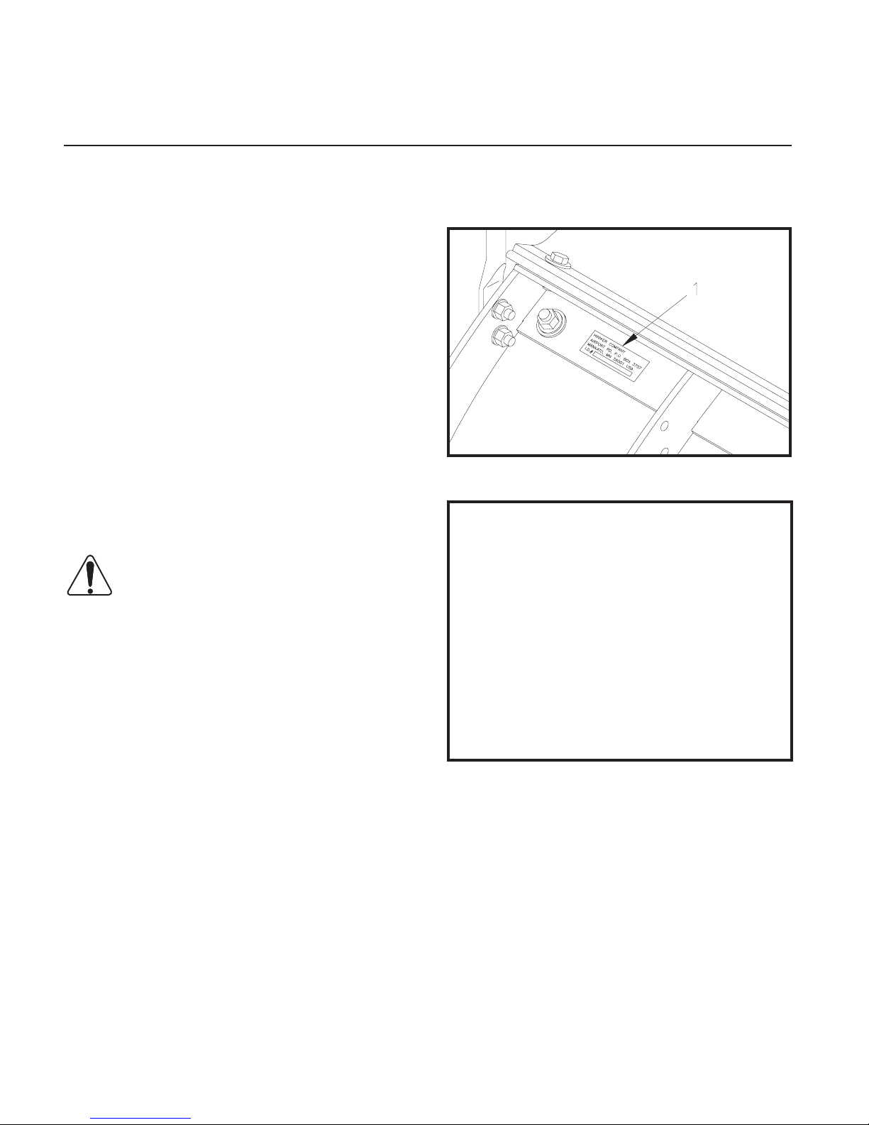
Your plow’s identification number decal is at location (1) in the following illustration.
DWG NO. 6066
Record the following information for later reference
when obtaining service parts:
Purchase Date ____________________________
Purchaser’s Name _________________________
All references to LEFT or RIGHT are defined as
viewing the plow from the cab of the truck.
This Operator’s manual is shipped with this
equipment. Contact your Hiniker dealer for additional copies.
Always obtain original Hiniker service parts.
Substitute parts could adversely affect equipment performance and warranty.
Check that your dealer has forwarded to Hiniker
company the delivery report form along with the
plow identification number because it helps to
maintain maximum service and warranty benefits. This does not put you on any mailing list,
and information thereon is not available to others.
Dealer’s Name ____________________________
Machine Serial No._________________________
Page 5

SAFETY
Safety 3
This is a safety alert symbol. It alerts
an operator to information concern-
ing personal safety. Always observe
and heed these symbols and instructions,
otherwise death or serious injury can result.
Operator safety is a principle concern in equipment design and distribution. However, many
accidents occur because a few seconds of
thought, and a more careful approach to handling, were ignored.
Accidents can be avoided by knowing and following the precautions cited in this manual.
GENERAL SAFETY
1. Read this manual thoroughly. Make sure
the operator understands it and knows
how to operate this equipment safely. This
equipment can kill or injure an untrained or
careless operator and bystanders. If you
sell this equipment, ensure the new owner
acknowledges receipt of this manual.
BEFORE OPERATION
1. Discipline yourself to visually check for
worn, damaged or cracked parts before
starting use. Replace these with genuine
Hiniker parts.
2. Escaping hydraulic oil under pressure can
penetrate the skin, causing serious injury.
Do not use your hand to check for leaks.
Use a piece of paper or cardboard to nd
suspected leaks.
Tighten all connections before pressurizing
hydraulic lines.
If uid is injected into the skin, get medical
attention immediately to prevent serious infection.
3. Check all controls and operating functions
of the machine in a safe area before starting to work.
2. This plow is intended for plowing snow
only. Plowing gravel, rocks, etc., or using
the plow for any purpose other than plowing
snow could result in harm to the operator or
bystanders or cause damage to the plow or
vehicle.
3. Do not service or otherwise handle a plow
in the raised position unless it is securely
blocked against unexpected falling.
4. Do not attempt to handle or service this
equipment, and direct others to do the
same, unless you know how to do it safely
and have the proper tools for the job.
5. Keep hands, feet, hair, and clothing away
from moving parts.
6. Do not alter the equipment.
DURING OPERATION
1. Always wear seat belts when operating a
motor vehicle.
2. Ensure everyone is clear of the machine,
especially away from blind areas of the operator, before starting, actuating hydraulics
or operating this equipment.
3. Do not plow snow at excessively high
speeds.
4. Avoid hitting objects that will damage your
plow or truck.
5. Set the brakes and stop the truck’s engine
before adjusting or servicing your plow.
AFTER OPERATION
1. Park the plow on a solid, level surface. Fully
collapse the lift cylinder with the upper lift
links before unhitching the plow to prevent
the plow frame from falling forward.
Page 6
4 Operating Procedures
OPERATING PROCEDURES
ATTACHING THE PLOW
Attachment prongs on the truck should be
mounted such that the bottom edge of the
prongs measure about 10 inches above the
ground. Prong receivers on the plow frame
should remain parallel to the ground and at the
correct height by fully retracting the lift cylinder
with the upper lift links before removing the plow
from the truck (See “Removing the Plow”) Ideally, the prongs on the truck should lift the plow
frame slightly when driving into the plow for attachment.
Powdered graphite applied on the prongs will
help the plow slide on and off more easily.
Check that prongs are in line with the receivers before driving into the plow. Set the parking
brake in the truck to prevent it from creeping
back out from the receivers.
Handle Pinned With Plow On Truck DWG NO. 6721
Pin the handle in the clevis with its klik pin.
Failure to pin the handle in place may allow
the plow to fall off the truck.
NOTE: Before connecting the plow’s wiring to
the truck, make sure power is switched “Off”
on the joystick controller.
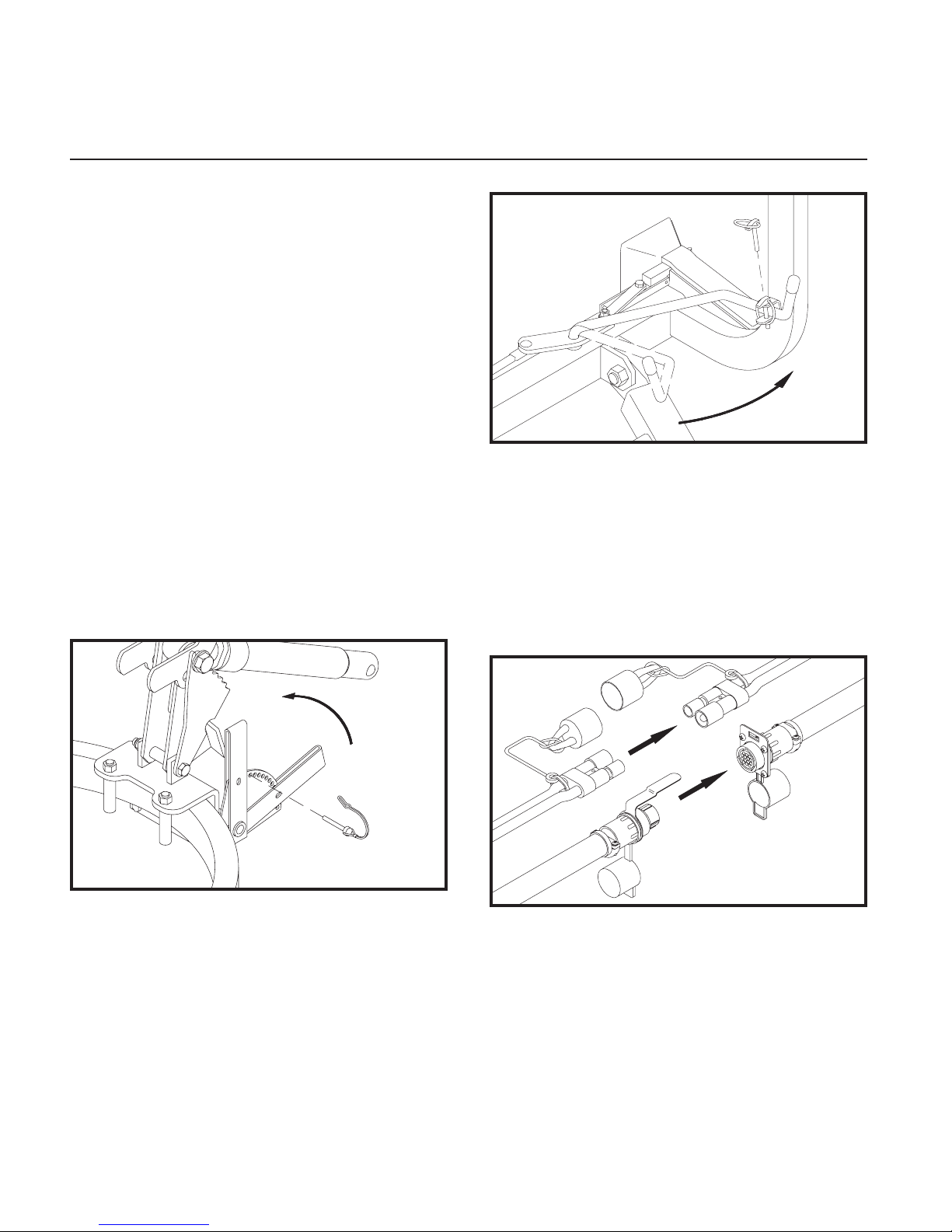
Remove the tab lock pin from the parking stand
index plate to raise the stand to its highest position. Reinstall the pin in the plate for transport.
Pull the latch handle into the clevis on the lift
frame to force the sliders through the notches
in the prongs and receivers. Check that both
sliders are fully engaged.
DWG NO. 5617A
Alignment Tab and Slot DWG NO. 6697
Plug in the two electrical connectors between
the plow and the truck after latching the plow.
The alignment tab on the 16-pin plug will
mate with the slot on the mating receptacle to
ensure proper connection.
Page 7
Operating Procedures 5
Check that the plow headlamps and turn signals
are operational, and headlamps are aimed correctly. Test the lift and angling cylinders in a safe
area before using the plow.
To make alignment of the plow easier in the future,
mark a point on the back of the head lamp, a point
on the hood near the front of the truck and a point
on the windshield that are in line when you are
seated behind the steering wheel. Line up these
three points when driving into the plow.
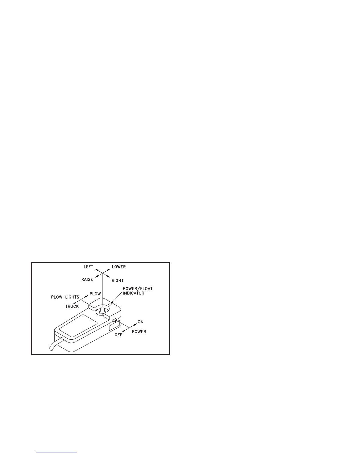
THE JOYSTICK CONTROLLER
The joystick control box has slide switches for controlling power to the snowplow and for switching
from the truck headlights to the headlights on the
plow.
The joystick controller raises and lowers the plow
and angles the blade left or right.
NOTE: Drawings 4176 and 4177 show the raise
and lower functions of the joystick controller as
received from the factory. Functions may be reversed to suit the preference of the operator by
following the instructions on page 22 for switching
the controller joystick and face plate.
NOTE: When removing the plow, remember to
place the headlight switch in the “Truck” position
to return power to the truck’s headlights.
Raise or lower the plow by moving the joystick to
the “Raise” or “Lower” position. Hold the plow at
an intermediate height by releasing the controller
from the “Raise” position when the plow reaches
the desired height.
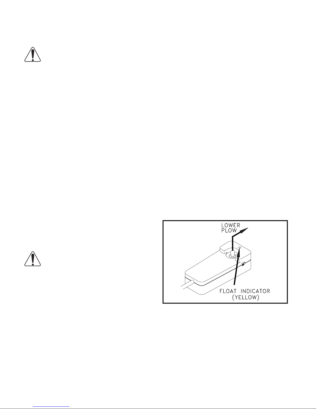
Moving the controller to the “Lower” position will
lower the blade to the ground and allow the plow to
“Float” along the contour of the ground while plowing snow.
A yellow light on the control box indicates the plow
is in the oat mode. Momentarily moving the joystick to the “Raise” position will remove the plow
from the oat condition and the yellow indicator will
return to green.
Move the joystick left or right to angle the blade.
Release the joystick when the blade is at the desired angle.
TRANSPORTING THE PLOW
The vehicle’s electrical power must be turned on
before the control box will function.
Joystick Control Box DWG NO. 4176
Place the on/off switch on the joystick control box
in the “On” position to supply power to the snowplow. A green light will indicate power is on.
Move the headlight slide switch on the control box
to the “Plow” position to change from the truck lights
to the snowplow lights. Activate high beam/low
beam and turn signal/parking lamps from the truck
as you normally would without the plow attached.
The extra weight of the snowplow on your truck
will impair handling response and increase braking
distance.
The plow will also block some airow to the vehicle’s cooling system, possibly causing the vehicle to overheat. Therefore, it is important not to
exceed speeds above 45 mph when the plow is
attached.
Remove the plow if you must drive your truck for
long distances when the temperature is warm.
Raise the blade to a position where it will not interfere with the headlights before driving.
Transport the plow with power to the joystick control box switched off to prevent accidental lowering
of the plow.
Never adjust the blade height or angle the blade
while driving.
Page 8
6 Operating Procedures
PLOWING SNOW
WARNING: Always wear a seat belt
when plowing snow. Sudden contact
with a hidden object can result in seri-
ous personal injury.
Inspect areas to be plowed before snowfall for
potential hazards, and mark obstructions with
stakes that will be seen when snow covers the
ground. Identify any emergency equipment and
utility outlets that may need to be cleared in the
event of a storm. Prepare a plan beforehand for
clearing snow from tight or enclosed areas and
locate sites for stacking snow.
Adjust the skids at the back of the moldboard
according to the surface to be plowed. The bottom of the skids should be about 1/2” below the
cutting edge when plowing gravel roads or lots.
Skids should be even with the cutting edge on
hard surfaces such as asphalt or concrete.
snow until a working area is cleared. Work small
areas in multiple passes to push snow to outer
edges. Generally, 6 inch snow can be plowed
with the entire blade width; 9 inch snow with
3/4 of the blade width; 12 inch snow with 1/2 of
the blade width. Local conditions will determine
how much work can be done before stalling or
getting stuck.
PARKING
Lower the plow to the ground when parking your
truck for a long period of time with the plow attached. Place the on/off switch in the “Off” position to prevent the plow from drawing power
from the truck battery. The plow’s power unit
may continue to draw electrical current from the
truck battery if the control switch is left on; possibly resulting in insufficient charge to start the
truck.
REMOVING THE PLOW
Always plow snow as it is accumulating. Wet
snow may weigh about 12 pounds per cubic
foot. The weight of snow being pushed by your
plow may increase to several tons.
Allowing snow depth to grow to unmanageable
levels can cause difficult removal problems and
can be costly in terms of wear on equipment.
WARNING: Serious personal injury
can result from plowing at excessive
speeds, as well as costly damage to
equipment and property, if an obstruction is
encountered while plowing. Do not exceed
10 mph while plowing.
Plow snow in the lowest truck gear to transfer
maximum power to the cutting edge. Clear areas in front of buildings first. Back drag snow
away from buildings by driving to the building
with the plow raised, then dropping the blade to
pull snow away from buildings.
Clear large lots by angling the blade and creating a single path. Roll snow to outer edges
of the lot by taking successive passes with the
blade angled.
When plowing very deep snow, it may be necessary to raise the blade and shear off layers of
To remove the snowplow from your truck, park
on a solid level surface with the blade straight.
Lower the plow to the ground and leave the controller in the “Float” mode.
Lower Plow, Leave Controller in “Float” DWG. NO. 4177
NOTE: The plow control box must be in the
“Float” mode to move the cylinder rod. If the cylinder rod does not retract with power on and the
controller in float, loosen the packing nut on the
lift cylinder up to 1-1/2 turns to reduce friction.
With the plow lowered to the ground and the
controller in the ”float” mode, push down on the
upper lift links to fully retract the lift cylinder rod.
Page 9
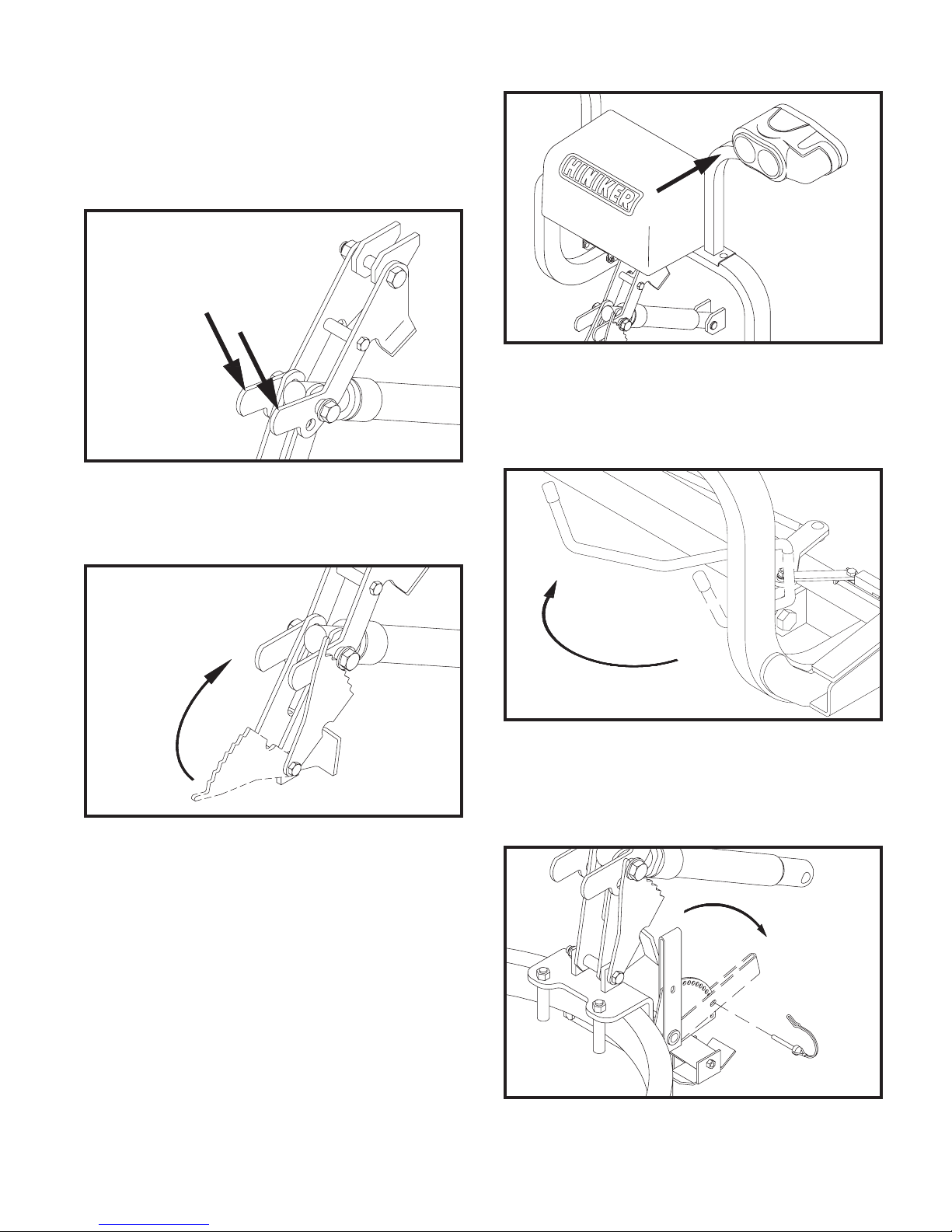
Retracting the lift cylinder will orient the prong
receivers correctly for reattaching the plow later.
Failure to retract the lift cylinder rod will allow
the lift frame to fall forward, possibly causing
personal injury or damage to plow components.
Retract Cylinder With Upper Lift Links DWG NO. 6000
Operating Procedures 7
Push Lift Frame Back DWG NO. 6005
Swing the latch handle open until the latch
sliders are fully removed from the attachment
prongs.
Rotate the stop plate up to contact the spacer
bushing on the lift cylinder bolt.
Rotate Stop Plate DWG NO. 6004
Gently push back on the headlight bracket to
tilt the lift frame back as far as possible, then
release the bracket to allow the weight of the lift
frame to lock the stop plate in place.
Swing Handle To Remove Sliders DWG NO. 6722
Lower the parking stand to the ground by removing the tab lock pin from stand index plate, then
swinging the stand to the ground with the lever.
Lower and Pin Parking Stand DWG NO. 5251A
Reinstall the pin in the index plate through the
hole in the lever to hold the stand in place.
Page 10

8 Operating Procedures
Disconnect the electrical connectors by pulling
them straight out from the receptacles. Do not
twist the connectors, twisting will damage the
connector pins or the wiring harness.
Place dust caps on connectors to prevent contamination.
Disconnect Plugs DWG NO. 6698
Back inside the truck, return control of the headlights to the truck and switch power off on the
snowplow control box, then slowly back the
truck out from the plow.
Turn Off Lights and Power DWG NO. 4164
NOTE: The stop plate will automatically fall forward as soon as the lift cylinder is fully extended for raising the blade prior to transporting the
plow.
If the snowplow won’t be used for an extended
period of time, the prong weldment can be removed from the truck by removing the hex bolts
that fasten it to the truck mount frame.
Page 11

TROUBLE SHOOTING
Trouble Shooting 9
GENERAL
1. Check to see that the motor is wired correctly with tight connections, for the proper
voltage.
2. Check reservoir oil level.
PROBLEM
1. Plow does not attach to vehicle
2. Pump motor does not run
A. Receivers are tipped forward
B. Prongs recoil out of receivers
C. Park stand pinned too low
A. Defective solenoid
B. Defective pump motor
C. Weak or defective battery
D. Bad electrical connections
E. Defective joystick control box
F. Blown fuse supplying power
POSSIBLE CAUSE
when attaching
to control box
3. Check that wiring harness relay connections are wired correctly
4. Check for external leakage at cylinders,
hoses and power unit.
REMEDY
A. Fully collapse lift cylinder and
rotate stop plate up to brace
the lift frame before removing
plow from truck.
B. Slowly drive into receivers
and set parking brake
C. Lower receivers by adjusting
park stand
A. Replace solenoid
B. Replace brushes or pump
motor
C. Charge or replace battery
D. Clean and tighten connec-
tions
E. Replace control box
F. Replace fuse
3. Pump runs with joystick in
neutral position
4. Plow will not lower
5. Hydraulic cylinder does not
function or functions slowly,
motor runs
6. Plow does not remain raised
with joystick in “neutral” position
A. Defective solenoid
B. Defective joystick control box
C. Wiring short
A. Reversed wiring on valve
block
B. Defective joystick control box
C. Defective lift return valve or
coil
A. Weak or defective truck bat-
tery
B. Oil level low
C. Hydraulic connection leak
D. Solenoid valve not opening
properly
A. Leakage through pump check
valve
B. Leakage through solenoid
lowering valve
C. Internal leakage in cylinder
D. Defective joystick control box
A. Replace solenoid
B. Replace control box
C. Locate and repair
A. Correct wiring
B. Replace control box
C. Replace valve or coil
A. Charge or replace battery
B. Add oil (do not overll)
C. Tighten or redo connection
D. Replace valve
A. Clean valve, or replace
B. Clean valve, or replace
C. Repack or replace cylinder
D. Replace control Box
Page 12

10 Trouble Shooting
PROBLEM
7. Angling cylinders relieve too
easily or too difcultly while
plowing
8. Oil leaks from cylinder(s)
9. Battery goes dead with power
to the control box on and joystick in neutral position.
10. Battery goes dead with power
to the control box off.
11. Plow parking/turn lights are
dim
12. Plow does not clean-up snow
from low areas
13. In extremely cold temperatures, the oil in the hydraulic
system is thickened, causing
slow functioning of the plow
POSSIBLE CAUSE
A. Relief pressure set too low or
too high
A. Loose packing
B. Defective cylinder
A. Short in wiring
B. Defective joystick control box
A. Short in wiring
A. Bad connection(s)
B. Lights not properly grounded
A. Controller not in oat mode
A. Cold temperatures
REMEDY
A. Have relief pressure adjusted
by Hiniker snowplow dealer
A. Tighten packing 1/8 turn
B. Repack or replace cylinder
A. Locate and repair
B. Replace control box
A. Locate and repair
A. Repair connection
B. Properly ground
A. Controller should be in the
oat mode
A. As the system warms, the oil
will thin out and function normally
B. Select Hiniker Cold Flow Hy-
draulic Oil for plowing in extremely cold temperatures
14. Pump chatters when raising
plow
15. Oil running out of cap on hydraulic reservoir
16. Vehicle overheats with the
plow on
17. Plow lights do not operate
with plow attached
18. Truck headlights do not operate properly with plow removed
A. Hydraulic oil low
A. Plowing on steeply inclined
terrain
B. Too much oil
A. Vehicle coolant level low
B. Ice and snow buildup in grill
C. Insufcient airow to engine
compartment
A. Light switch on joystick con-
trol box in “truck” position
B. Defective relay
C. Faulty light switch on joystick
control box
D. Blown fuse on vehicle acces-
sory feed
A. Light switch on joystick con-
trol box in “plow” position
B. Defective relay
A. Add hydraulic oil until chatter-
ing stops. Do not overll
A. Avoid excessive inclines or
change direction of plowing
B. Remove excess oil
A. Add coolant
B. Remove ice and snow
C. Transport plow at lower
speeds
A. Move switch to “plow” posi-
tion
B. Replace relay
C. Replace joystick control box
D. Replace fuse
A. Move switch to “truck” posi-
tion
B. Replace relay
19. Poly moldboard is bowing or
cracking
A. Moldboard bolts are too tight.
A. Loosen the bolts so the plas-
tic can expand and contract
Page 13

MAINTENANCE
Maintenance 11
WARNING: Do not service or otherwise handle a plow in the raised position unless it is securely blocked
against unexpected falling.
Dependable snowplow operation is the result
of following good maintenance procedures.
Inspect your plow frequently to ensure that
all parts are working smoothly, and develop a
schedule for maintenance at required intervals.
GENERAL
Wash salt and dirt off the plow before storage.
Touch-up any chips or scratches in the paint
and apply a light coating of grease to extended
cylinder rods to prevent corrosion.
HYDRAULIC SYSTEM
The majority of snowplow operational problems
are caused by bad oil in the hydraulic system.
Hydraulic oil should be changed every year for
best performance.
Select Hiniker Cold Flow Hydraulic Oil or an
equivalent oil that meets military specification
5606, for plowing in extremely cold temperatures.
Re-attach hydraulic hoses and electrical wires
at the correct locations on the power unit.
Pour hydraulic oil into the power unit reservoir
until the reservoir is half full. Angle the plow full
left or right to fill the angling cylinder with oil,
then add more oil until the oil reaches the fill line
- about 1 1/4 inches from the top. Do not overfill
the reservoir.
Cycle the plow left and right and up and down,
to purge any air trapped in the system.
Check the oil level with the plow on the ground.
Add oil to the fill line, if necessary, but do not
overfill the reservoir.
ELECTRICAL MAINTENANCE
Periodically check all electrical connections for
proper fit and remove any contamination that
may be present.
To prevent contamination always place dust
caps on connectors when not in use. This is
particularly important when the plow is being
stored. A light coat of dielectric grease is recommended to reduce corrosion of the contacts and
to make connecting and disconnecting easier.
To change hydraulic oil, disconnect the electrical wiring harnesses from the snowplow power
unit and uncouple three hydraulic lines. Unbolt
the power unit from the plow, and remove it to a
clean working area that can capture any spilled
oil.
Carefully unbolt the oil reservoir from the power
unit and discard old oil. Purge old oil from the
angling cylinders by forcing rods to retract.
Clean the suction filter at the pump inlet and
wipe any metal shavings off the magnet on the
pump.
Re-attach the reservoir onto the power unit and
re-connect the power unit on the snowplow before adding new hydraulic oil.
Before each season check vehicle battery and
electrical system for proper operation. A weak
battery, dirty terminals, or faulty charging system may cause improper operation and possible
failure of the joystick controller.
Before every plowing season, and throughout
the season, check the snowplow headlamps for
proper function and aim. Refer to sections titled
“System Check-Out” and “Headlamp Aiming
Procedure” in this manual for instructions.
Page 14

12 Maintenance
MECHANICAL COMPONENTS
Prior to the operation of a new snowplow, or one
which has been stored, inspect all hardware and
verify proper torque on all bolts and nuts in accordance with the recommended torque specifications.
GRADE 5 TYPE B & F LOCK NUT
TORQUE VALUES
Diameter Ft-lbs. N-m
5/16” 13-18 17-25
3/8” 23-33 31-44
1/2” 58-82 79-112
5/8” 117-165 158-223
GRADE 5 BOLT TORQUE VALUES*
Size Ft-lbs. N-m
1/4” 8-12 11-16
3/8” 29-41 39-56
1/2” 73-103 99-140
5/8” 146-206 198-279
Loose bolts can cause hole elongation and part
failure resulting in dangerous operating conditions and equipment breakdown.
Check all hardware periodically during operation
and keep tightened to specified torque values.
Replace worn bolts and lock nuts with grade 5
bolts and equivalent type B or type F lock nuts.
Type B lock nuts are plain hex; type F lock nuts
are flanged hex.
Inspect wear of cutting edges before every
plowing season and frequently throughout the
season. Replace the cutting edge before wear
reaches the main plow blade.
The 5/16” hex bolts in the latch sliders are factory retained with anaerobic threadlock. If removal or replacement of these bolts is necessary,
purchase new bolts with threadlocker from your
Hiniker dealer, or apply a commercially available
threadlock, i.e., Loctite 242 (blue) or Perma-Lok
HM118 (red), to standard 5/16-18 X 3/4” grade 5
hex bolts before reassembly.
Page 15
PLOW ASSEMBLY
Plow Assembly 13
GENERAL INFORMATION
WARNING: To prevent personal injury
or death, be certain to keep clear of
any parts that may drop when removing bundling straps, wires or brackets. Support heavy sections with hoist or blocks before removing wires or straps.
In the following instructions, left and right ma-
chine references are dened as being viewed
from the cab of the truck.
Be certain that hydraulic hoses and electrical
wires are safely routed and allow full motion of
moving parts. Secure loose wires with plastic tie
straps.
Some components are fastened at incorrect locations for shipping purposes.
All hardware should be tightened only enough to
insure safety during assembly. Torque hardware
to specied values, as shown in the following
chart, only after assembly has been completed.
PLOW ASSEMBLY
1. Place moldboard face down on cardboard
or other padding that will prevent scratches
in the paint.
Remove shipping brackets from the ends of
the moldboard assembly and save two sets
of 5/16 inch hex bolts, at washers and lock
nuts for reattaching the side markers later.
Remove the side markers from the mold-
board assembly and set aside for reassembly.
Remove both skid assemblies from their
shipping locations and reassemble at the
ends of the moldboard with one 1 inch
spacer and one 1/2 inch spacer beneath
the moldboard tube.
GRADE 5 TYPE B & F LOCK NUT
TORQUE VALUES
Diameter Ft-lbs. N-m
5/16” 13-18 17-25
3/8” 23-33 31-44
1/2” 58-82 79-112
5/8” 117-165 158-223
GRADE 5 BOLT TORQUE VALUES*
Size Ft-lbs. N-m
1/4” 8-12 11-16
3/8” 29-41 39-56
1/2” 73-103 99-140
5/8” 146-206 198-279
* applications without lock nuts
Replace worn bolts and lock nuts with grade 5
bolts and equivalent type B and type F locknuts.
Type B lock nuts are plain hex; type F lock nuts
are flanged hex.
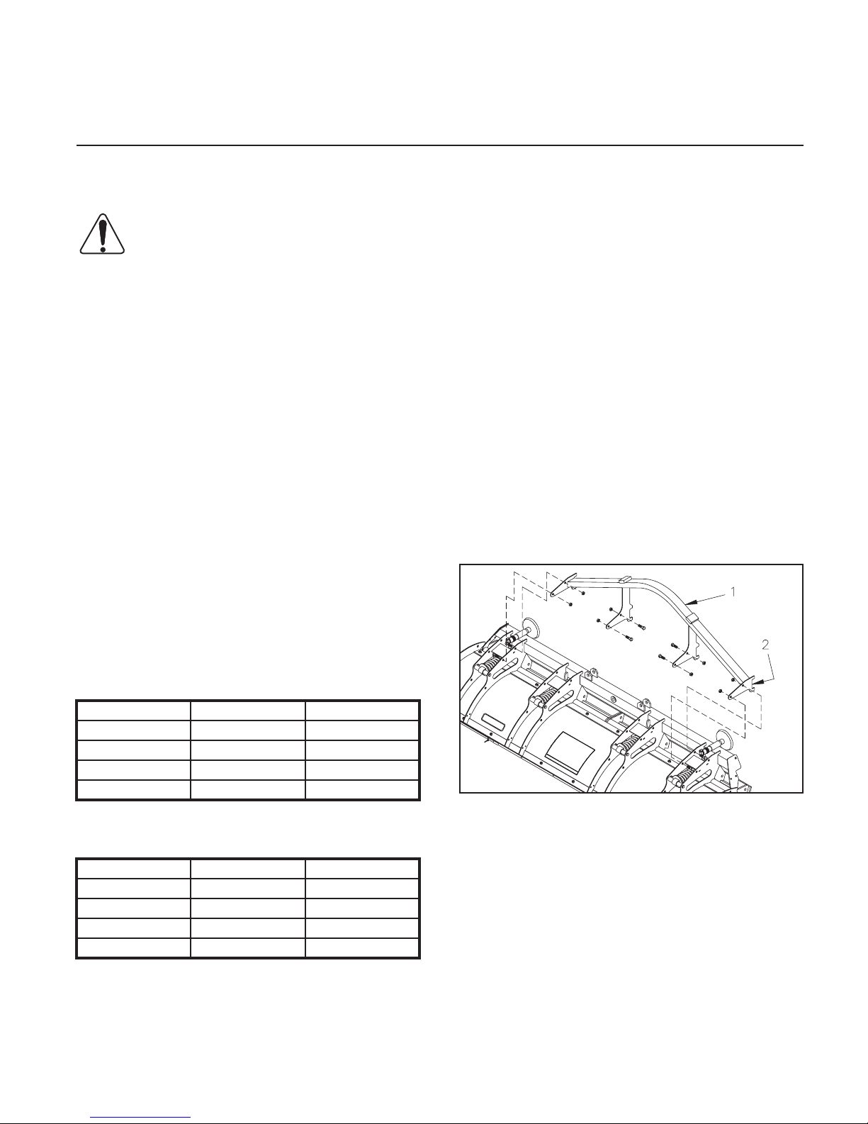
DWG. NO. 5618
Wrap hoist straps or padded chains around
the quadrant weldment, item 1 in drawing
5618 to support its weight.
Unbolt the quadrant from the back of the
moldboard assembly by removing eight hex
bolts and lock nuts. Rotate the quadrant to
its working position and line up eight holes
with holes in moldboard. Reassemble the
quadrant to the moldboard with eight hex
bolts and lock nuts previously removed.
Page 16
14 Plow Assembly
2. Open the frame crate and set aside the
power unit box, headlamp boxes and parts
box for later. Carefully lift the frame assembly from the crate by wrapping hoist straps
or padded chains around both ends of the
2 1/2 inch square tube at the back of the
frame assembly.
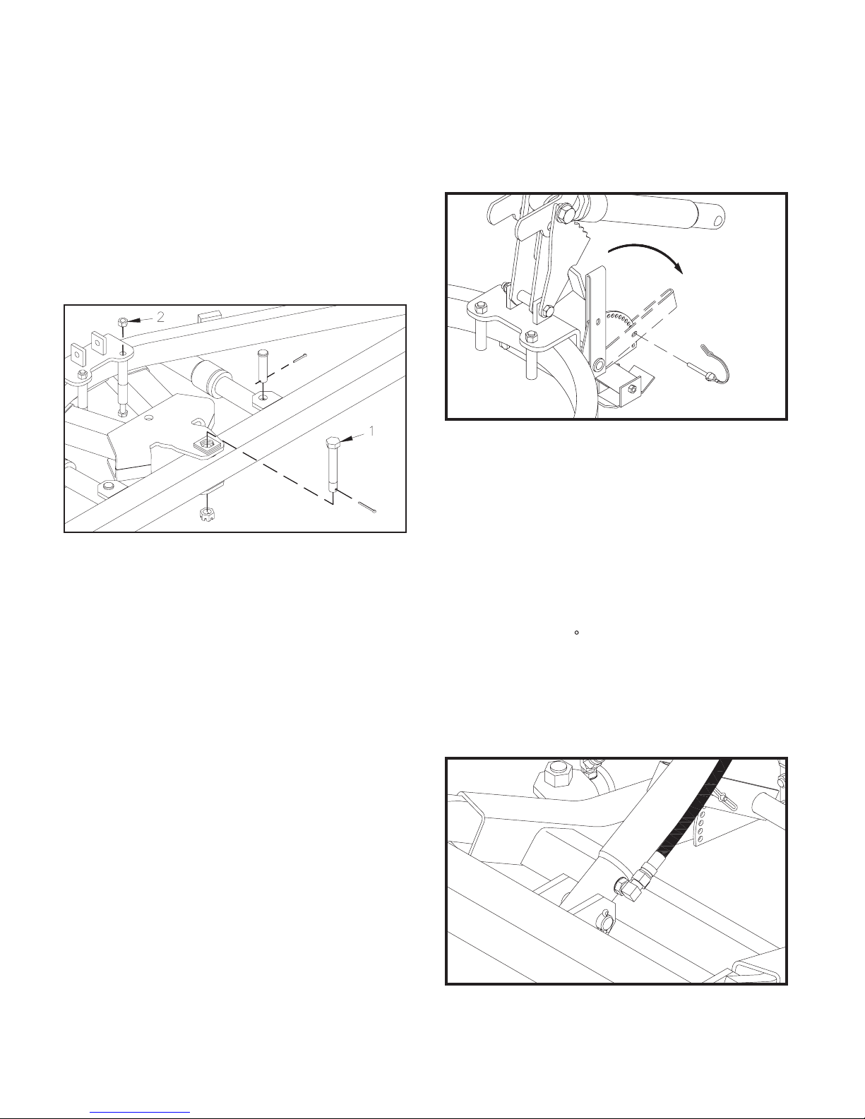
Remove the 3/4 inch hex bolt, arrow 1 in
drawing 5420A, and two 1/2 inch hex bolts,
and spacers, arrow 2, from the push frame.
3. Tip the moldboard and frame assembly to
their working position with a hoist or fork
truck. Pin the parking stand to hold the
square tubes of the push frame parallel to
the ground.
Lower and Pin Parking Stand DWG NO. 5251A
Swing the lift frame to its approximate work-
ing position and hold it with a hoist or forklift
for assembly of the lift mechanism.
DWG. NO. 5420A
Align the push frame hitch plates with the
pivot hole in the moldboard tube, then reassemble the 3/4 inch hex bolt, slotted nut
and cotter pin. Install the nut so that the assembly is secure, but frames will pivot.
Reassemble the two 1/2 inch hex bolts,
spacers and lock nuts at their original locations and fully tighten hardware.
Remove clevis pins from the rod ends of the
two angling cylinders. Loosen the plugs in
the cylinder ports and extend the cylinder
rods to the lugs on the back of the moldboard. Pin the rods between the lugs with
the clevis pins and cotter pins.
The bottom surface inside the two prong
receiver channels should measure approximately 10 inches above the ground in the
working position.
4. Locate a 90 O-ring/are adapter in the
hardware bag and the lift cylinder from the
parts box. Turn the O-ring end into the port
of the lift cylinder so that the are end is toward the rod end of the cylinder when tightened.
DWG NO. 4202
Page 17
Plow Assembly 15
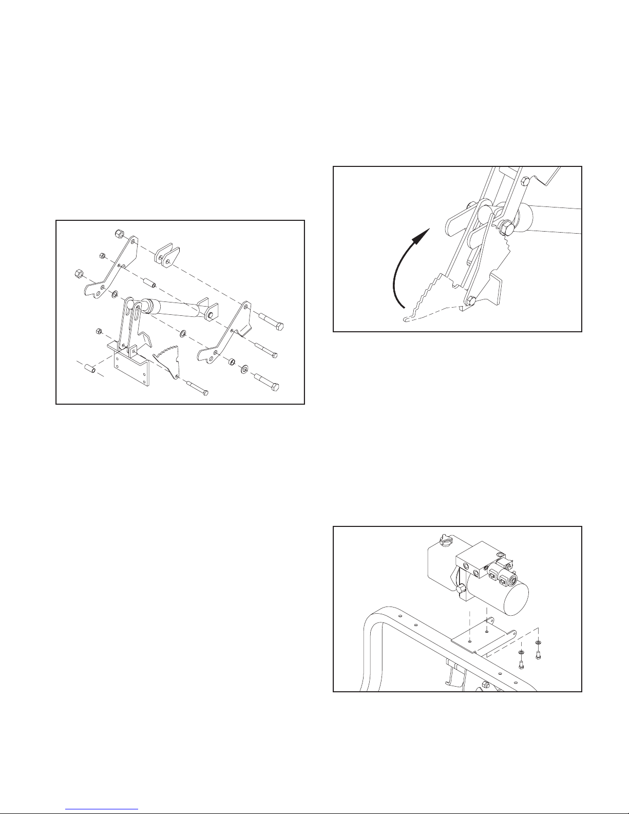
Pin the base of the cylinder between the
center lugs of the lift frame with the 3/4” x 3”
clevis pin. The hydraulic tting should be on
the right side of the cylinder.
Remove four lift links and the stop plate kit
from the parts box. From the hardware bag
remove two 3/4 inch hex bolts, two 3/4 inch
I.D. shim washers and one 3/4 inch nylon insert lock nut. Also remove the 1/2 inch hex
bolt and upper link spacer bushing.
Bolt through the upper set of bottom holes
in the upper links for most vehicles, then
secure the assembly with the 3/4 inch lock
nut from the stop plate kit. Bolting through
the lower set of holes will increase downward plow travel for taller trucks, but reduce
lift height.
DWG NO. 6004
DWG NO. 6585
Identify the RH and LH upper and lower links
by referring to drawing 6585. Assemble the
links with their stop surfaces away from the
lift cylinder.
Remove the 1/2 inch hex bolt and spacer
from between the tabs on the push frame.
Slide the stop plate onto the bolt, as shown
in the drawing, then bolt the two lower links
inside the tabs, with the spacer between the
links.
Assemble the two upper lift links outside
the lugs on the lift frame with a 3/4 inch x
4 1/4 inch hex bolt and nylon insert lock
nut.
Bolt the upper link spacer bushing between
the two upper links with the 1/2 inch hex
bolt and lock nut.
Place the at washer and spacer bushing
from the stop plate kit onto the remaining
3/4 inch hex bolt, then complete the lift
mechanism assembly by bolting the lift cylinder rod, lower links and two shim washers
between the upper links.
Rotate the stop plate up to contact the spac-
er bushing on the lift cylinder bolt. Gently
push back on the upper lift frame tube, then
release to allow the weight of the frame to
lock the stop plate in place.
5. Before assembling the power unit on the lift
frame, scrape a small amount of paint from
the two mount holes in the lift frame to provide a good electrical ground for the turn
signals and parking lights.
DWG NO. 6595
Mount the power unit on the lift frame with
two 3/8” x 3/4” hex bolts and two 3/8” lock
washers. The plastic reservoir of the power
unit should be to the left side of the plow.
Page 18
16 Plow Assembly
DWG NO. 6484
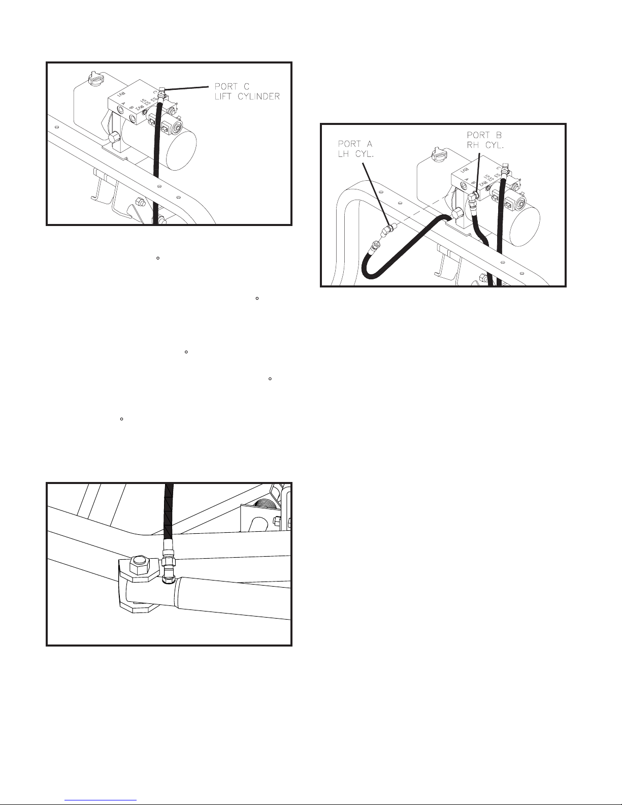
Locate three 90 O-ring/are adapters in
the hardware bag. Turn the O-ring end of
one adapter into the top port (Port C) of the
power unit so that it points about 45 to the
right and to the rear when viewed from the
top.
Turn the other two 90 adapters into ports
A and B from the back of the power unit so
that the are ends point at opposite 45 angles from center. See drawing 6485.
Connect one hose to the tting on the top of
the power unit (Port C), then route the hose
ahead of the lift frame tube before assembling to the fitting on the lift cylinder.
DWG NO. 6485
Connect the remaining two hoses to the t-
tings from ports A and B at the back of the
power unit. Route both hoses ahead of the
lift frame tube before assembling the hose
from port A to the LH side angling cylinder
and the hose from port B to the RH side angling cylinder.
Install 45 O-ring/are adapters into the
ports of the angling cylinders so that the
are ends are nearly parallel to the mount
lugs of the push frame.
DWG NO. 4205
Three identical hydraulic hoses are in the
parts box. Each hose has a swivel nut on
each end that will assemble to the adapters
from the power unit and three cylinders.
The tting on the LH side angling cylinder
may have to be adjusted slightly to route
the hydraulic hose to best avoid interference with the latch handle and the lift links.
Use plastic tie straps to secure all hydraulic
hoses away from lift link stops.
6. Before assembling the headlamp brackets on the lift frame tube, scrape a small
amount of paint from the three holes in each
bracket and from the four holes in the frame
tube to provide a good electrical ground for
the turn signals and parking lights.
Mount the headlamp brackets to the lift
frame tube with four 3/8” x 2” carriage bolts
and anged lock nuts from the hardware
bag in the parts box.
Remove the LH and RH headlamps from
their boxes and mount on the brackets with
hardware from the headlamp boxes.
Page 19
Plow Assembly 17
DWG NO. 6502
DWG NO. 6312B
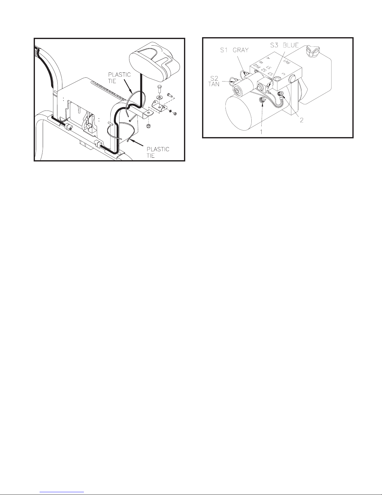
Use plastic tie straps to band headlamp
cables above and below the brackets at the
locations shown to provide clearance for
the power unit cover later.
Refer to sections titled ”System Check-Out”
and “Headlamp Aiming Procedure” in this
manual for aiming instructions.
7. Identify the plow power cable assembly
and plow wiring harness in the parts box. A
ground wire harness for the solenoids is in
the power unit box.
The power cable for the snowplow has two
cables with ring terminals on one end and
a two pin connector on the other and measures about 38” long.
The plow wiring harness has a 16-pin con-
nector on one end and the other end has
connectors labeled “DRIVER SIDE” and
“PSNGR SIDE” for the headlamps and
three loose wires with spade terminals.
Refer to drawing 6502. Attach the ring ter-
minal of the solid red (or red-striped) wire
of the power cable assembly to the terminal
on the power unit at location 1.
Fasten the ring terminal of the solid black
wire of the power cable assembly and the
ring terminal of the solenoid ground wire
harness to the terminal on the motor at location 2.
Connect the three black wires of the ground
harness to solenoids S1, S2 and S3.
Connect the gray wire from the wiring har-
ness to solenoid S1. S1 extends the right
side of the plow to plow left.
Connect the tan wire from the wiring har-
ness to solenoid S2. S2 extends the left
side of the plow to plow right.
Connect the blue wire from the wiring har-
ness to solenoid S3. S3 lowers the plow.
The ground wire for the solenoids has one
7 inch long wire and two wires 11 inches
long. There is a 1/4 inch ring terminal on the
common end and three spade receptacles
on the remaining ends.
NOTE: To prevent corrosion apply a light coat
of dielectric grease to all electrical connections
including ring and spade terminals.
Connect the RH headlamp to the wiring har-
ness end labeled “PSNGR SIDE” and the
LH headlamp to the end labeled “DRIVER
SIDE”.
Ensure connections are fully mated for
proper sealing. There should be no gaps
between connector halves. Secure these
cables to the frame with plastic ties.
Page 20
18 Plow Assembly
Truck Battery On Passenger Side
WARNING: Disconnect truck battery
before beginning electrical installation
to avoid shock hazard.
The motor solenoid, underhood wiring harness,
power cable and joystick control box are located
in the parts box shipped with the snowplow frame.
NOTE: To prevent corrosion apply a light coat of
dielectric grease to all electrical connections including ring and spade terminals.
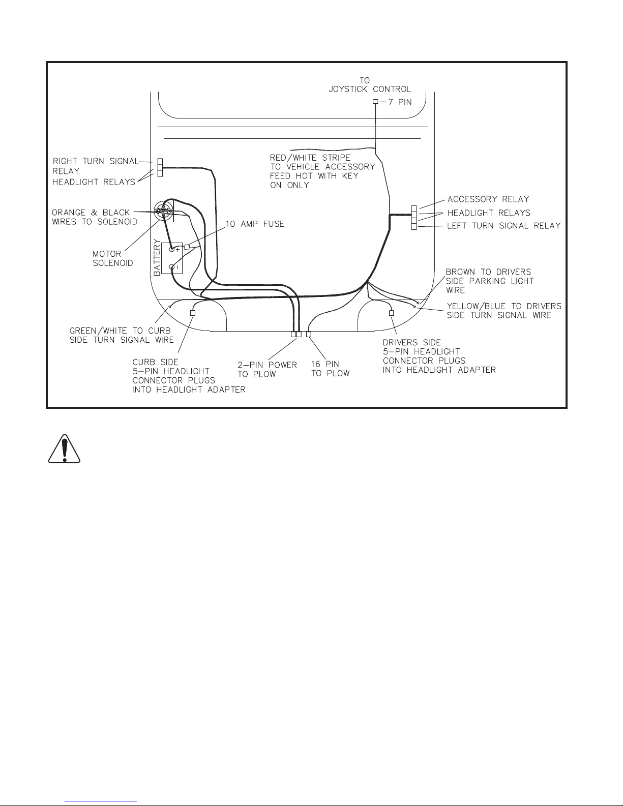
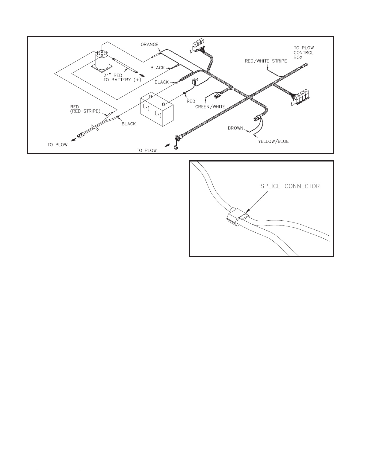
8. Refer to drawing 6699. Lay the underhood
harness in it’s approximate position for nal
assembly with the 7-pin circular connec-
tor near the driver’s side rewall. Place the
16-pin connector just left of center near the
grill, the set of four relays near the driver’s
side inner fender and the other set near the
passenger side inner fender. Place the 5-pin
headlight connectors at the respective headlights.
9. Determine the location of the vehicle battery. If the battery is located on the right
(passenger) side or if there are two batteries
DWG NO. 6699
congured as a 12 volt system, then pro-
ceed to step 10.
If the battery is located on the left (driver)
side of the vehicle, then the wiring harness
will need to be modied.
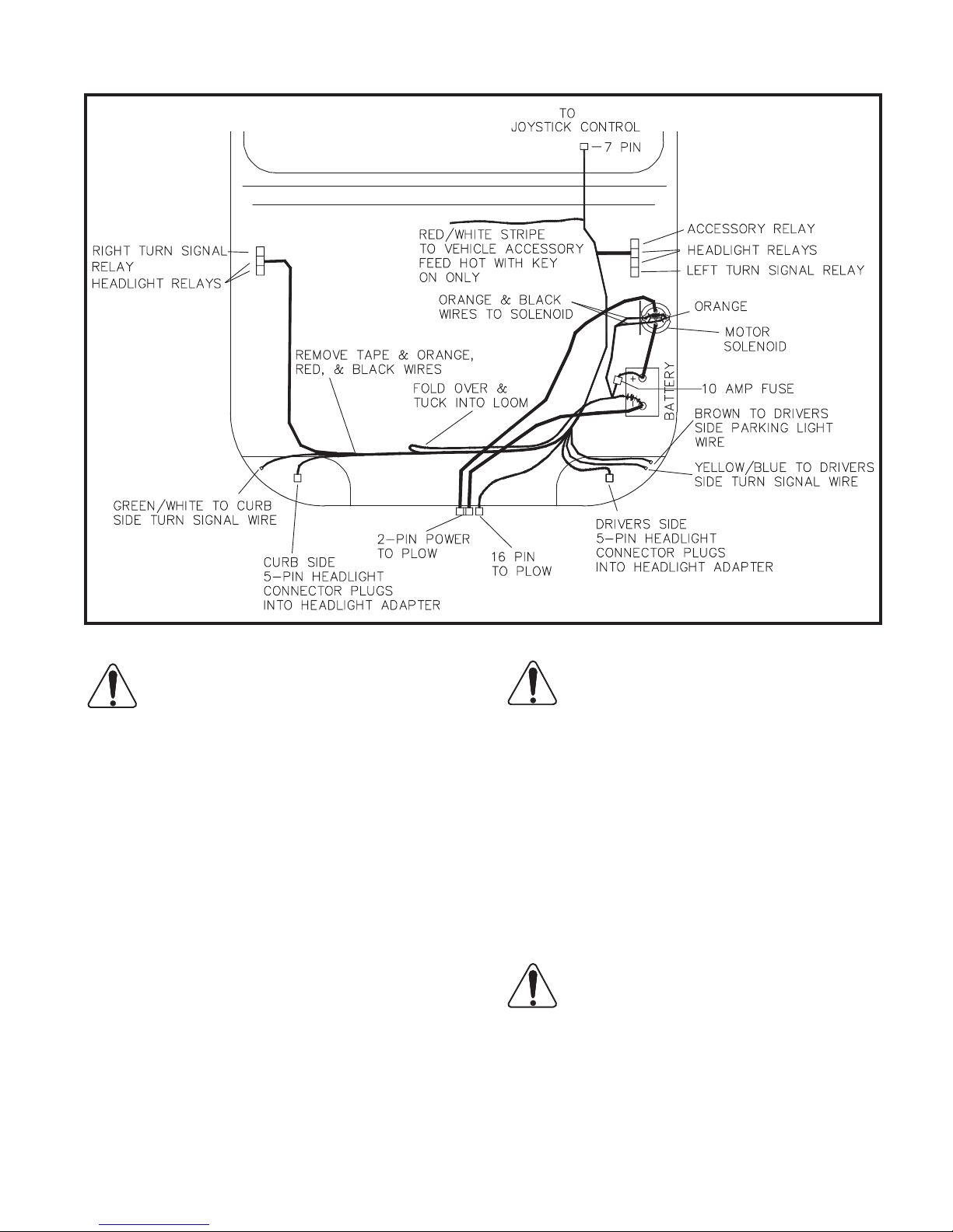
Refer to drawing 6700, Remove the tape
from the Black corrugated loom at the
points shown. Locate the Orange, Red,
and two Black wires. These wires connect
to the battery and motor solenoid located
next to the battery. Remove the four wires
from approximately 33 inches of the loom,
making sure the Red and Black wires are
long enough to connect to the battery. Tuck
these wires back into the loom as shown in
the drawing and retape the loom.
10. If there is no access hole in the drivers side
rewall then drill a 1-1/8 inch diameter hole.
Route the 7-pin circular connector through
the rewall into the cab compartment and
install the 4 inch grommet in the hole, if required.
Page 21
Plow Assembly 19
Truck Battery On Driver Side
CAUTION: Ensure that the relays will
clear any hood lift/spring mechanisms
before installation.
11. Select an area near the driver’s side inner fender to mount the four relay set. Drill
two 1/8” diameter holes and secure the relays using #8 x 1/2” self-tapping screws
from the hardware bag in the parts box.
Apply a light coat of dielectric grease on
the relays before inserting into holders.
NOTE: Always mount the relays with the wires
pointing down to prevent contamination.
Repeat this procedure and mount the three
relay set on the passenger side inner fender.
12. Splice the red with white stripe wire to the
vehicle’s switched 12 volt auxiliary electrical
circuit. This will prevent operation of the plow
without the vehicle key being on. This wire
controls the accessary relay that powers the
control joystick and solenoids.
DWG NO. 6700
CAUTION: To prevent injury or property damage caused by unintentional
plow movement when the key is removed from the vehicle, the red/white striped
wire must be connected to a switched power
source on the vehicle. Connecting to a power
source not controlled by the ignition switch
will allow movement of the plow with the vehicle key removed.
13. Connect the joystick control box to the 7-pin
connector inside the truck cab. Secure the
box at a safe location in the cab with the
strip of hook and loop fastener.
WARNING: Ensure that the motor so-
lenoid and associated wiring will clear
any hood lift/spring mechanisms before
installation.
IMPORTANT: Do not over tighten nuts on the
motor solenoid terminals. Over-tightening causes
premature solenoid failure. Refer to torque specications on the solenoid.
Page 22
20 Plow Assembly
14. Select an area within 16 inches of the vehicle
battery for the motor solenoid. Using the solenoid as a template, mark and drill two 3/16
inch diameter holes then fasten the solenoid
with two 1/4” x 1/2” long self tapping screws
from the hardware bag in the parts box. Connect the Black wire to one of the small posts
on the solenoid, connect the Orange wire to
the remaining small post, polarity is not important.
DWG NO. 6701
15. Safely route the 16-pin circular connector
through the grill of the vehicle to a location
that will be easily accessible with the plow attached.
16. Refer to drawing 6701. Install the underhood
power cable by rst connecting the Black
cable and the three Black wires from the harness to the minus (-) post of the vehicle’s battery. Connect the Red (or Red striped) cable
to the motor solenoid. Route the power cable
to the grill near the 16-pin connector.
Connect the red fused wire from the harness
and the 24 inch Red cable to the plus (+) terminal of the battery or battery access post.
Connect the other end of the 24 inch Red
cable to the motor solenoid.
17. Locate three blue connector splices in the
hardware bag in the plow’s parts box.
DWG NO. 4165
Using a blue splice, crimp the single brown
wire from the underhood harness into the vehicle’s driver’s side parking light wire.
Using a blue splice, crimp the single yellow
with blue stripe wire from the underhood harness into the vehicle’s driver’s side turn signal
wire.
Using a blue splice, crimp the single green
with white stripe wire from the underhood harnessinto the vehicle’s curbside turn signal wire.
18. Select the proper headlight adapter for your
vehicle, specic instructions are included with
each kit.
The headlight adapter kit consists of two iden-
tical adapters. Install the adapters according
to the instructions included with the kit, then
connect to the 5-pin connectors of the underhood wiring harness.
19. Secure all cables away from hot or moving
components with cable ties.
Page 23
Plow Assembly 21
This completes the Electrical Installation.
20. At this point, the mount kit should be assembled onto the truck.
Prongs from the truck mount kit should be at
a height that will slightly lift the plow frame
when attaching the plow. Prong receivers
on the plow frame should be parallel to the
ground when attaching the plow. Apply powered graphite on the truck prongs to help the
plow to slide on and off more easily.
Check the oil level with the plow on the
ground. Add oil to the ll line, if necessary, but
do not overll the reservoir.
NOTE: New hydraulic cylinders will leak a small
amount of oil until packings become saturated and
produce a good seal. If leakage is excessive, or if
leaking continues after initial cycling, tighten the
cylinder packing nut in 1/8-turn increments until
leaking stops.
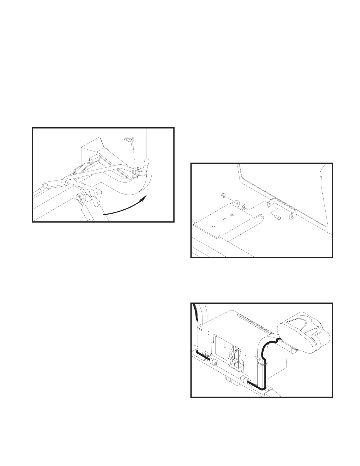
21. Fasten the power unit cover to the lift frame
bracket with two 1/4” x 3/4” screws, at washers and lock nuts from the hardware bag in
the parts box. Tighten the lock nuts so that
the assembly is secure, yet the cover hinges
freely.
Handle Pinned With Plow on Truck DWG NO. 6721
Attach the plow onto the truck by driving the
truck prongs into the receivers on the plow
frame. Pull the latch handle into the frame
clevis to move sliders through the notches in
the prongs and receivers. Pin the handle in
the clevis with its klik pin.
Raise the parking stand to its highest position
and repin.
Connect the two electrical cables from the
plow to their corresponding receptacles on
the truck.
Select Hiniker Cold Flow Hydraulic Oil or an
equivalent oil that meets military specication
5606, for plowing in extremely cold temperatures.
Pour hydraulic oil into the power unit oil res-
ervoir until the reservoir is half full. Angle the
plow full left or right to ll the angling cylinders
with oil, then add more oil until the oil reaches
the ll line - about 1 1/4 inches from the top.
Do not overll the oil reservoir.
Cycle the plow left and right and up and down
to purge any air trapped in the system.
DWG NO. 6310
When the cover is closed, rods from the
latch handles should extend behind the
light brackets to hold the cover in place.
DWG NO. 6070A
22. Locate the 5/16” x 1” hex bolts and lock nuts
removed earlier. Attach the side markers to
the top of the end moldboard ribs with this
hardware.
Page 24
22 System Check-Out And Joystick Conguration
SYSTEM CHECK-OUT
NOTE: The power cable and wiring harness must
be connected between the snowplow and truck to
test the functions of the headlights and power unit.
Vehicle ignition must be switched on.
1. Move the headlight switch on the joystick controller to the “TRUCK” position and turn on
the vehicle headlights. High and low beams
should operate on the truck.
2. Move the switch to the “PLOW” position.
Plow lights should operate in both high and
low beams. Vehicle headlights should be off.
3. Test the parking lights and turn signals. Lights
on the plow and truck should operate at the
same time.
4. In an area clear of bystanders, test control
functions by raising and lowering the plow
and angling side to side.
To reverse the angle functions, exchange the
tan and gray wires on the power unit.
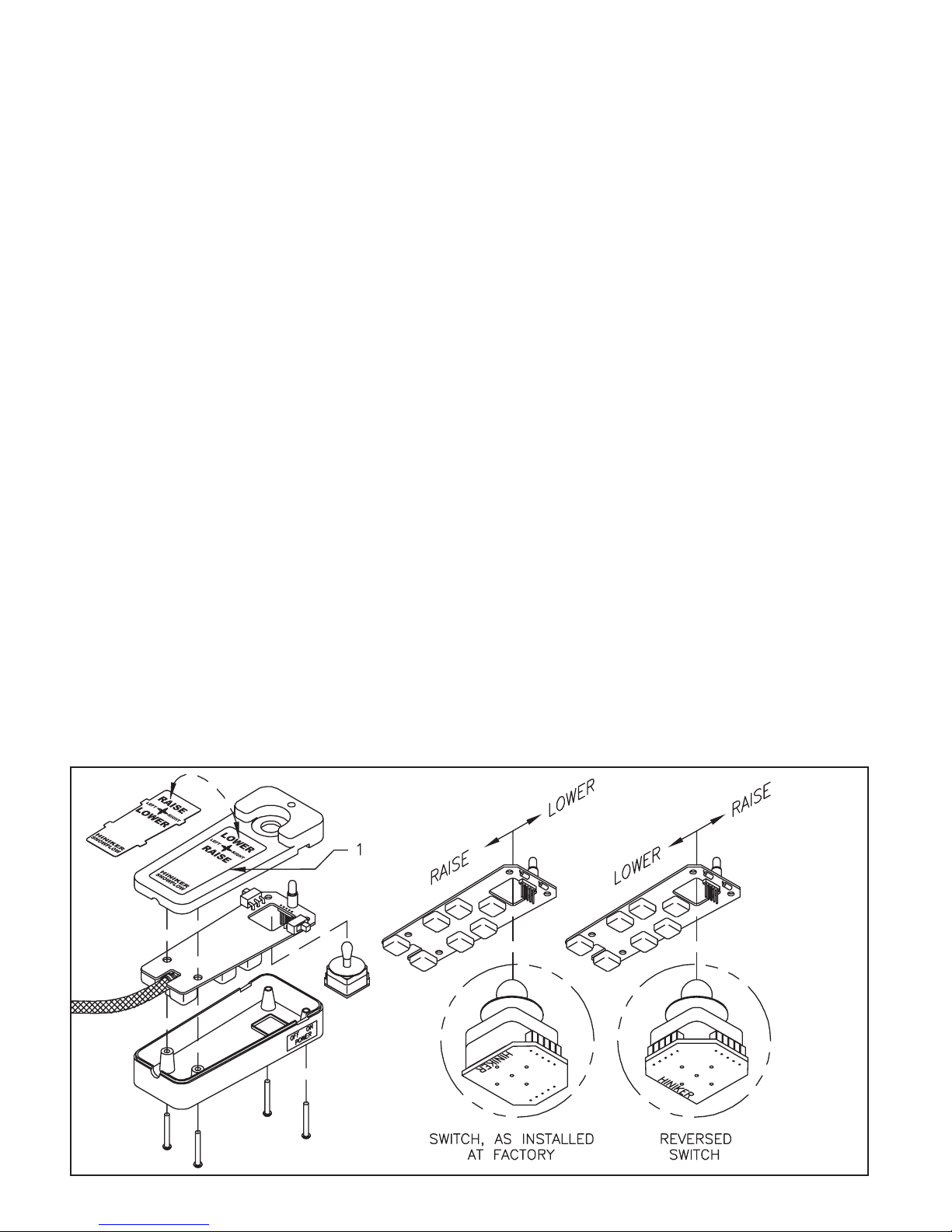
backward and lowers the plow when the joystick is
pushed forward. These functions can be reversed
by reassembling the joystick switch and face plate.
To reverse the face plate, pry the plate away from
the controller by inserting a small screwdriver
along the side of the plate at location 1 in drawing
5722. Flip the plate over, then reinstall by gently
squeezing the long sides together and sliding the
four tabs into slots in the controller top.
To reverse the joystick switch, remove four screws
from the back of the controller and remove the
main circuit board assembly from the case halves.
Gently pull on the edges of the small circuit board
at the base of the joystick switch to remove the
switch from the ve pins on the main circuit board.
Rotate the switch 90O, then gently push the switch
back onto the ve pins.
Insert the main circuit board assembly back into
the case top, making sure the joystick is properly
seated and the harness strain relief is inside the
case.
Raise and lower functions may be reversed,
as follows.
JOYSTICK CONFIGURATION
As supplied from the factory, the snowplow controller raises the plow when the joystick is pulled
Reassemble the case with the four screws, checking that wires are not pinched between bosses.
Test the controller on the snowplow or a plow tester to verify that raise and lower functions match
arrows on the face plate.
DWG. NO. 5722
Page 25
Headlamp Aiming Procedure 23
HEADLAMP AIMING PROCEDURE
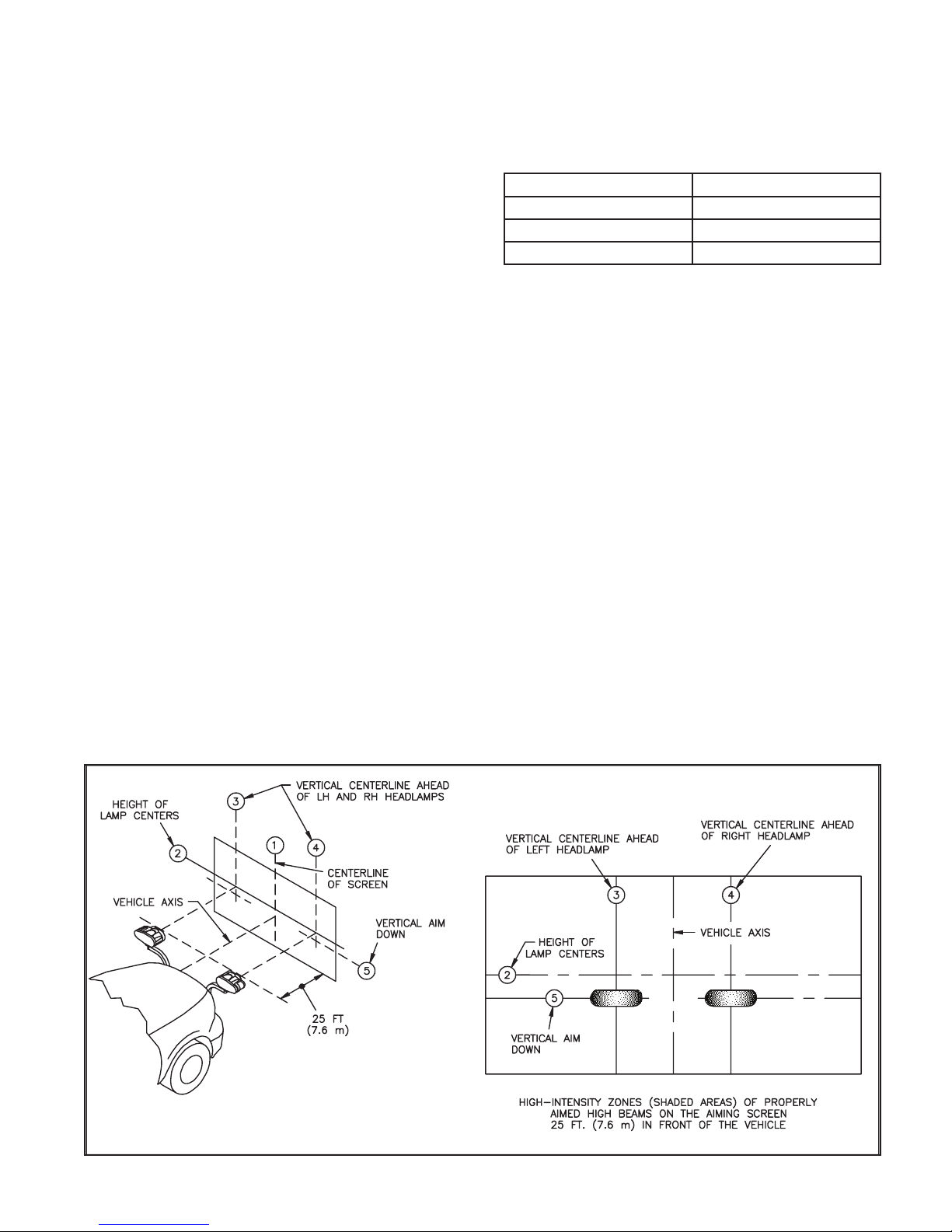
1. Park the vehicle with the plow attached on a
level surface 25 ft (7.6 m) from a at, unobstructed light-colored wall.
With no load on the vehicle other than the
driver, snowplow and rear ballast weight, in-
spect the vehicle for proper tire ination and
broken or sagging suspension components.
Check functioning of any automatic vehicle
leveling systems and any specic manufacturer’s instructions pertaining to vehicle
preparation for headlamp aiming. Stabilize
the suspension by rocking the vehicle sideways.
2. Mark a vertical line (line 1) on the wall with
black tape, or other means, directly ahead of
the center of the vehicle.
Mark two additional vertical lines (lines 3 and
4) offset 20 1/2 inches (52 cm) from the rst
line representing the distance between the
two plow headlamps.
4. Refer to the following chart then mark a sec-
ond horizontal line below the rst (line 5), as
required.
Headlamp Centerline Height Vertical Aim Down
22 to 36 in (56 to 90 cm) 0
36 to 48 in (90 to 120 cm) 2 in (5 cm) Down
48 to 54 in (120 to 140 cm) 4 in (6.4 cm) Down
5. Wipe the lamp lenses clean and check for
proper switching and function.
Activate the plow lamp HIGH beams to il-
luminate toward the wall. Focus the center
of the LH light beam on the intersection of
lines 3 and 5. Focus the center of the RH
light beam on the intersection of lines 4 and
5.
Tighten the headlamp mounting hardware
to 70 ft.-lbs. (95 N-m) maximum to hold the
headlamps in position.
3. Measure the height from the ground to the
center of the plow headlamps, then mark
a horizontal line (line 2) on the wall at that
same height.
DWG NO. 6598
Page 26
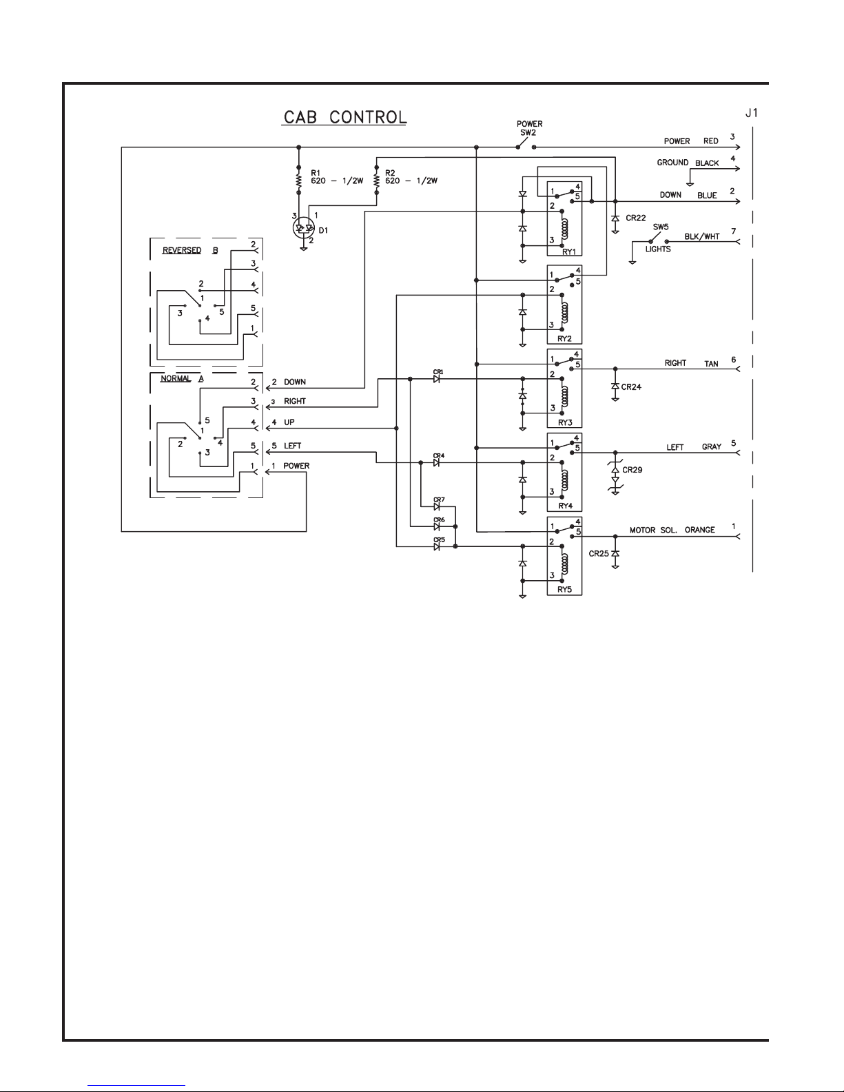
24 Wiring Harness
Page 27
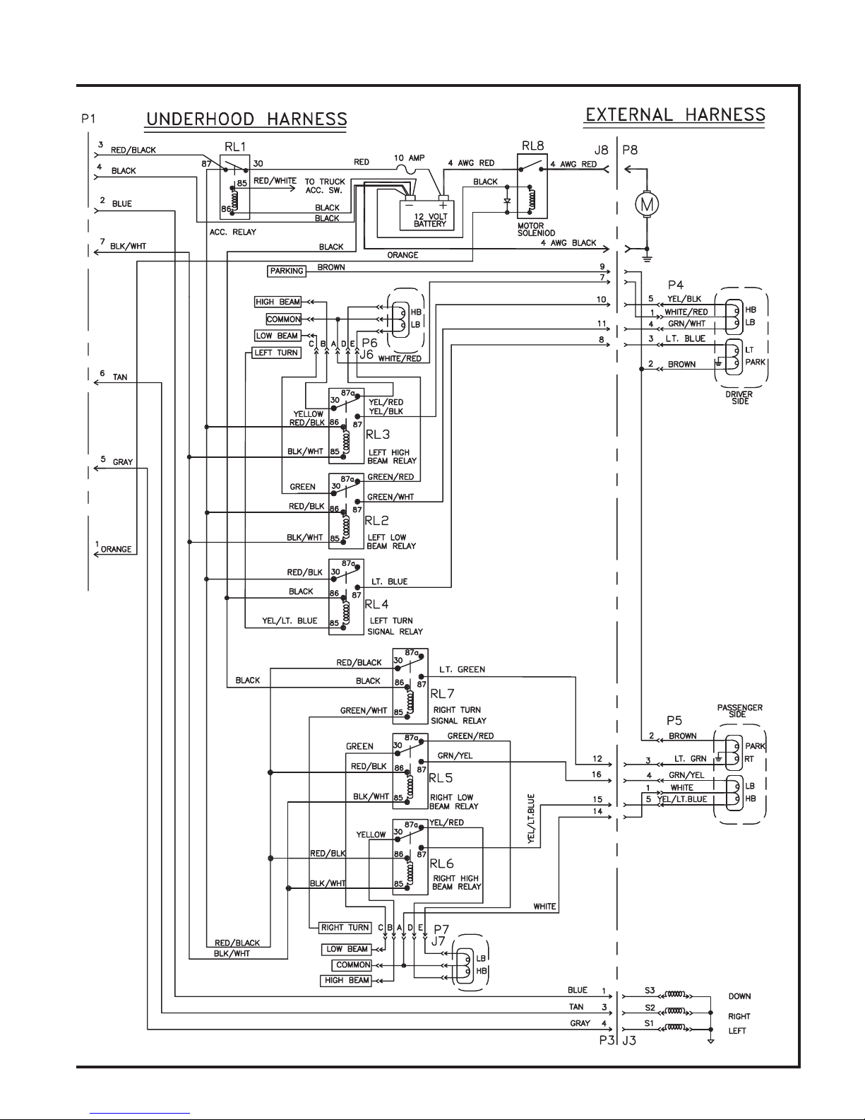
Wiring Harness 25
DWG NO. 6704
Page 28
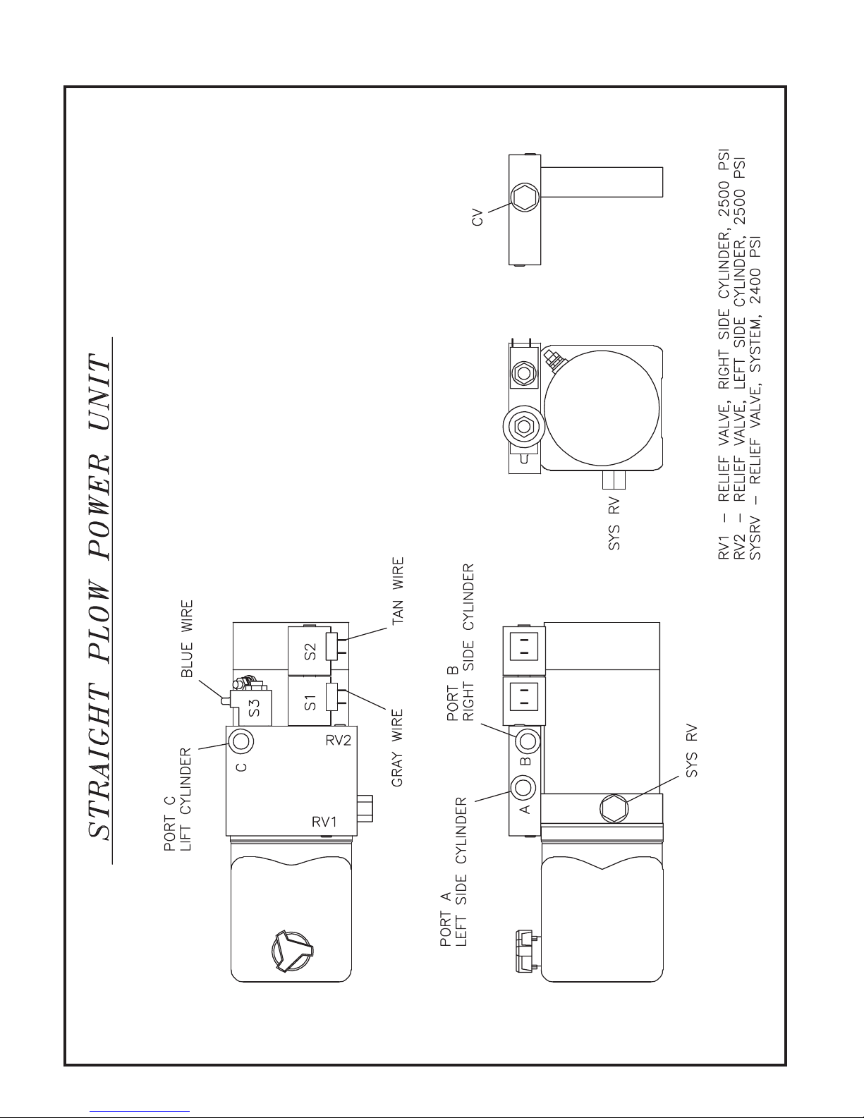
26 Plow Power Unit
DWG NO. 6487
Page 29
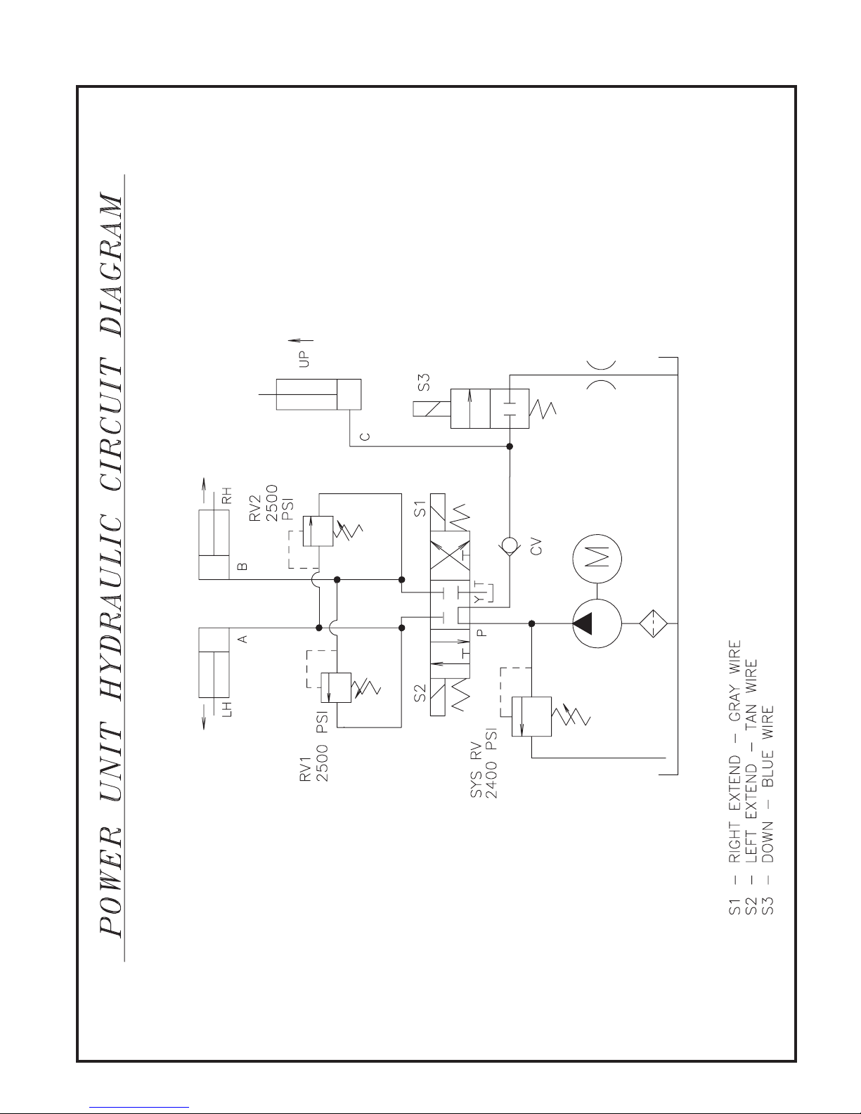
Power Unit Hydraulic Circuit Diagram 27
DWG NO. 5408
Page 30

28 Specifications
SPECIFICATIONS
Blade Width 8’ 9’
Plow Width at 31
Blade Height 30” 30”
Cutting Edge 3/8” x 6” 1084 steel
Weight 711 lbs. 768 lbs.
Recommended Hydraulic Fluid
Hydraulic Fluid Capacity 2 qts.
High Beam Bulb One # H1, 12V 55W
Low Beam Bulb One # H7, 12V 55W
Turn Signal/Parking Bulb
7’4” 8’3”
Hiniker Cold Flow
Mil Spec 5606
or equivalent
One # 1157 heavy duty double contact
32/3 C.P. 12 VDC
Motor Solenoid 12 VDC continuous duty, sealed
Wiring Harness Fuse 10 AMP
Page 31

Hiniker Warranty 29
HINIKER WARRANTY
HINIKER SNOWPLOW LIMITED WARRANTY
The only warranty Hiniker Company (Hiniker) gives and the only warranty that any Hiniker dealer is authorized to
give on behalf of Hiniker is as follows: (NO EMPLOYEE OR REPRESENTATIVE IS AUTHORIZED TO CHANGE
THIS WARRANTY IN ANY WAY OR GRANT ANY OTHER WARRANTY.)
Hiniker warrants to the original purchaser of a Hiniker snowplow that Hiniker will repair or replace any defects
in material and workmanship that occur within two years from date of retail delivery except the following items:
Hiniker warrants that it will repair or replace any defects in materials or workmanship with respect to the paint
nish, any accessories, and service parts and components for a period of one year from date of retail delivery.
Hiniker’s obligation and liability under this warranty is expressly limited to repairing or replacing, at Hiniker’s
option, at an authorized Hiniker dealer location, the defective parts at no charge to the original purchaser.
HINIKER MAKES NO OTHER WARRANTY, EXPRESS OR IMPLIED AND MAKES NO WARRANTY OF
MERCHANTABILITY OR OF FITNESS FOR ANY PARTICULAR PURPOSE.
HINIKER’S OBLIGATION UNDER THIS WARRANTY SHALL NOT INCLUDE ANY TRANSPORTATION
CHARGES TO OR FROM THE AUTHORIZED HINIKER DEALER LOCATION OR ANY LIABILITY FOR
INCIDENTAL, INDIRECT OR CONSEQUENTIAL DAMAGE OR DAMAGES OF ANY KIND FOR LOST PROFITS
OR DELAY. If requested by Hiniker, products or parts for which a warranty claim is made are to be returned freight
prepaid to our factory. Any improper use, operation beyond rated capacity, substitution of parts not approved by
Hiniker Company, or any alteration or repair in such manner as in our judgment affects the product materially and
adversely shall void this warranty.
Hiniker reserves the right to make improvements or changes to any of it’s products without notice. Such
improvements or changes shall not trigger any obligation by Hiniker to update, modify or change any products
previously sold by Hiniker.
HINIKER does not warrant the following:
1. Used products.
2. Any product that has been repaired, modied or altered in a way not approved by Hiniker Company.
3. Depreciation or damage caused by normal wear, lack of reasonable and proper maintenance, failure
to follow Operators Manual Instructions, misuse, lack of proper protection during storage, or accident.
4. Parts replacement and service necessitated by normal wear or maintenance including, but not limited
to, cutting edges, hoses, snowplow skid shoes, blade marker guides and hardware.
5. Paint nish damage caused by normal wear.
Hiniker does not assume any liability for any damage to a motor vehicle resulting from the attachment or use of
a Hiniker snowplow. Compliance with applicable motor vehicle regulations is the responsibility of the installer.
Attachment of a Hiniker snowplow to a motor vehicle is at the risk of the purchaser.
It is the responsibility of the original snowplow purchaser to verify the original date of purchase.
A DELIVERY REPORT FORM must be lled out and received by Hiniker with 30 days of retail delivery at the
address below to initiate the warranty coverage.
HINIKER COMPANY
58766 240th St.
P.O. Box 3407
MANKATO, MN 56002-3407
PHONE (507) 625-6621 -- FAX (507) 625-5883
www.hiniker.com
 Loading...