

Hiniker 6000 Instruction Manual
SERIES 6000 ROW CULTIVATOR
HINIKER
ROW CULTIVATOR
SERIES 6000
INDEX
SERIAL NUMBER ENDING 100 OR HIGHER
SECTION 1 RIGID SERIES ROW CULTIVATOR
SECTION 2 FOLDING SERIES ROW CULTIVATOR
SECTION 3 HYDRAULICS
SECTION 4 COMPONENT PARTS BREAKDOWN
SECTION 5 OPTIONAL EQUIPMENT
PART NUMBER 81004224 Rev. E
11/1 0
Page I

PARTS
Part Number 81004224 Rev. E November 2010 Parts Books/Hiniker/81004224RevE
It is the policy of Hiniker Company to constantly
improve its products whenever it is practical to
do so.
Hiniker Company must therefore reserve the
right to redesign or change its equipment or
component parts thereof without incurring the
obligation to install or furnish such changes on
the equipment previously delivered.
INSTRUCTIONS FOR ORDERING PARTS
1. The item numbers in the illustrations correspond to the same item numbers in the description list. An assembly having a part
number can be ordered. All other parts must
be ordered individually. The quantity in the
“number required” column is the number of
parts used in this area of the machine. The
term “A/R” for number required indicates “as
required” where the quantity may vary. Order all parts by their number and name. Do
not use the item number.
5. Dealers must indicate how to ship.
6. Collect phone calls are not accepted.
7. Address parts orders as follows:
HINIKER COMPANY
58766 240th St.
P.O. BOX 3407
MANKATO, MN 56002-3407 USA
Phone (800) 433-5620
Fax (800) 637-3991
INSTRUCTIONS FOR RETURNING PARTS
FOR ADJUSTMENT
1. To assure prompt handling of claims, your
dealer or distributor should follow standard
claim procedure and forward claims within
thirty (30) days of any part failure or malfunction believed to be a warranty claim,
to Hiniker Company claims department for
processing.
2. All references to left and right, front and rear
apply to the machine as viewed from the
rear of the machine, facing forward in the
direction of travel.
3. Always mention the identication number of
the model and serial numbers found on the
name plate of the unit on which the part is to
be used. Much delay and confusion can be
avoided when correct numbers are specied
on parts order and correspondence.
4. Owners, order all parts through your local
dealer.
2. No returned part will be accepted unless they
are transportation prepaid and accompanied by the packing list copy of the returned
goods authorization form, or the packing list
copy of the warranty claim form.
3. Parts returned should have a tag attached
with sender’s name and address clearly
printed.

SERIES 6000 ROW CULTIVATOR
SECTION 1
RIGID SERIES
ROW CULTIVATOR
PAGE 2 RIGID TOOLBAR 4 ROW 30, 36/38 INCH
S
E
C
1
SERIES 6000 6 ROW 30
6 ROW 36/38 INCH RIGID
6 ROW 40 INCH
8 ROW 30 INCH RIGID
8 ROW 36/38 INCH RIGID
8 ROW 36/40 INCH RIGID
(3/8” WALL TOOLBAR)
10 ROW 30 INCH RIGID
(3/8” WALL TOOLBAR)
11/1 0
Page 1
S
E
C
1
SERIES 6000 ROW CULTIVATOR
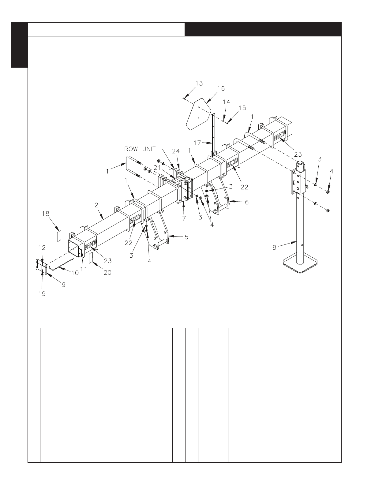
RIGID TOOLBAR
4 ROW 36138, 6 ROW 30, 6 ROW 36/38/40
8 ROW 30, 8 ROW 36/38140
REF.
NO.
Page 2
NUMBER
1
875-001-038
2
810-002-234
810-002-235
810-002-236
810-002-237
810-002-238
81004338
3
952-001-006
4
951-001-009
5
810-002-080
6
810-002-079
7
810-002-085
8
810-001-920
9
810-001-284
PART
DESCRIPTION QTY.
U-Bolt 3/4
Toolbar (170”) (4/36-38)
Toolbar (198”) (6/30)
Toolbar (246”) (6/36-38)
Toolbar (258”) (8/30) 6/40)
Toolbar (322”) (8/36-38)
Toolbar (338”) 3/8 Wall (8/36-38-40) (10-30)
Lock Washer 3/4 Inch
Hex Nut 3/4-10
RH Lower Hitch Assy (Includes Items 1, 3 & 4)
(See Sect. 4 Pg. 7)
LH Lower Hitch Assy (Includes Items 1, 3 & 4)
(See Sect. 4 Pg. 7)
Upper Hitch Assy (Includes Items 1, 3 & 4)
(See Sect. 4 Pg. 7)
Parking Stand Assy (Includes Items 1, 3 & 4)
(See Sect. 4 Pg. 6)
End Plate
10
1
1
1
1
1
20
20
2
2
11/1 0
REF.
NO.
10
11
12
13
14
15
16
17
18
19
20
21
22
23
24
25
PART
NUMBER
810-001-475
950-002-006
951-002-002
950-001-003
952-001-001
951-001-003
850-001-354
815-001-004
850-001-305
810-001-473
850-001-285
850-002-426
81004129
81004136
81004186
81004181
DWG. N O. 3011
DESCRIPTION QTY.
Block Removing Rod
Whiz Lock Bolt 5/16 x 3/4
Whiz Lock Nut 5/16-18
Hex Bolt 1/4-20 x 1
Lock Washer 1/4 Inch
Hex Nut 1/4-20
SMV Sign
SMV Mount Strap
Tape Reflector (Red)
Notice Decal
Tape Reflector (Yellow)
Caution Decal
6000 Decal
Hiniker Decal
Spacer Strap
Decal Bag (Includes Items 18, 19, 20, 21, 22
& 23)
1
8
8
2
2
2
1
1
2
1
2
1
2
2
2

SERIES 6000 ROW CULTIVATOR
SECTION 2
FOLDING SERIES
ROW CULTIVATOR
PAGE 2-3 FOLDING TOOLBAR
SERIAL NO. ENDING 100
8 ROW 30
PAGE 4-5 FOLDING TOOLBAR
SERIAL NO. ENDING 101 OR HIGHER
8 ROW 30
S
E
C
2
PAGE 6-7 FOLDING TOOLBAR
SERIAL NO. ENDING 100
8 ROW 36-38 12 ROW 30
PAGE 8-9 FOLDING TOOLBAR
SERIAL NO. ENDING 101 OR HIGHER
8 ROW 36-38-40
10 ROW 30 12 ROW 30
PAGE 10-11 FOLDING TOOLBAR
SERIAL NO. ENDING 100 OR HIGHER
12 ROW 36-38
12 ROW 40 16 ROW 30 18 ROW 28
11/1 0
Page 1
S
E
C
2
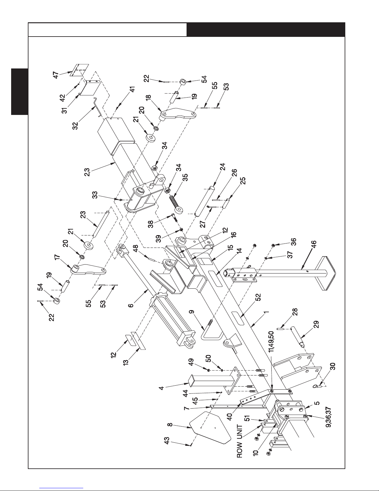
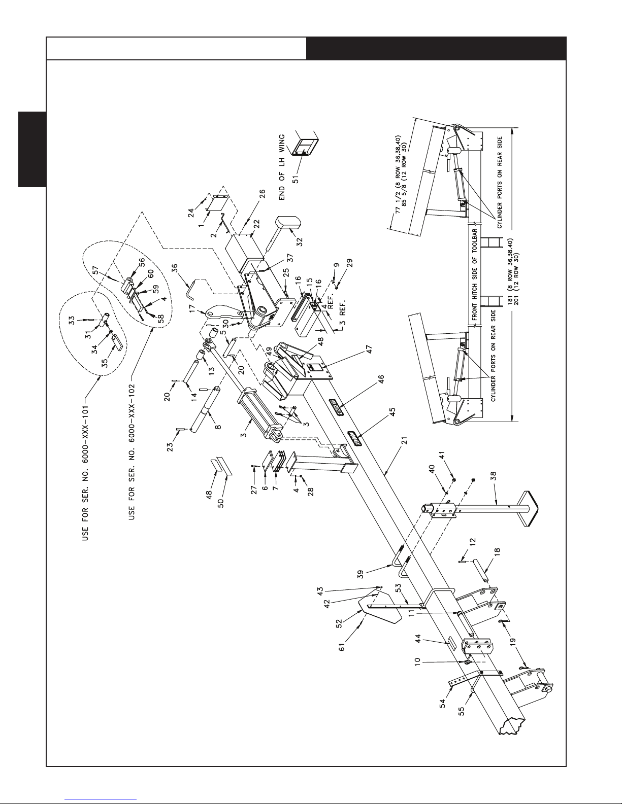
SERIES 6000 ROW CULTIVATOR
FOLDING TOOLBAR ASSEMBLY
SERIAL NO. ENDING 100
8 ROW 30
Page 2
DWG. N O. 2892
11/1 0

SERIES 6000 ROW CULTIVATOR
REF.
NO.
1
2
3
4
5
6
7
8
9
10
11
12
13
14
15
16
17
18
19
20
21
22
23
24
25
26
27
28
29
PART
NUMBER
810-002-337
810-002-351
810-002-352
810-002-164
810-002-085
81002580
815-001-004
850-001-354
875-001-038
850-002-426
950-001-181
850-001-980
850-001-305
81004136
850-001-306
850-001-285
810-002-157
810-002-156
81002674
845-001-150
810-001-255
953-003-017
81002675
810-002-155
850-001-200
953-003-023
953-005-002
953-003-002
810-002-485
DESCRIPTION QTY.
Center Frame Weldment
LH Wing Weldment
RH Wing Weldment
Stand Weldment
Upper Hitch Assembly (Includes Items 9, 36 &
37) (See Sec. 4 Pg. 7)
3 1/2 x 16 Dia. Cylinder SAE (See Sec. 3 Pg. 3)
SMV Mount Strap
SMV Sign
3/4 U-Bolt
Caution Decal
Hex Head Cap Screw 5/8-11 x 8 1/2 Gr. 5
Warning Decal
Tape Reflector (Red)
Hiniker Decal
Warning Decal
Tape Reflector (Yellow)
LH Link Weldment
RH Link Weldment
Tube
Spacer
Roller
Spring Pin 5/16 x 2
Link Pin
Hinge Pin
Hinge Pin
Spring Pin 5/16 x 3
Hair Pin Cotter .178 x 3 9/16
Spring Pin 1/2 x 2 1/2
Lower Hitch Pin
REF.
NO.
1
1
1
2
1
2
1
1
6
1
2
4
2
2
2
2
2
2
4
4
4
4
2
2
2
2
2
2
2
30
230-026-005
31
810-002-284
32
810-001-511
33
955-001-001
34
951-001-022
35
850-002-503
36
951-001-009
37
952-001-006
38
950-001-031
39
951-005-052
40
805-001-784
41
950-002-006
42
951-002-002
43
950-001-003
44
951-001-003
45
952-001-001
46
810-001-920
47
810-001-473
48
953-003-028
49
951-001-008
50
952-001-005
81004182
51
81004186
52
81004129
53
701-30004
54
81003138
55
953-003-008
PART
NUMBER
DESCRIPTION QTY.
Klik Pin
End Cover
Block Removing Road Short (8 Row 30 Fold)
Grease Fitting
Hex Nut 1-1/4
Eye Bolt 1-1/4
Hex Nut 3/4-10
Lock Washer 3/4 Inch
Hex Head Cap Screw 3/4-10 x 3 Gr. 5
Jam Nut 3/4-10
30° Bulkhead Plate
Whiz Lock Bolt 5/16 x 3/4
Whiz Lock Nut 5/16
Hex Head Cap Screw 1/4-20 x 1
Hex Nut 1/4-20
Lock Washer 1/4 Inch
Parking Stand Assembly (Includes Items 9, 36
& 37) (See Sec. 4 Pg. 6)
Notice Decal
Spring Pin 1/2 x 2 3/4
Hex Nut 5/8-11
Lock Washer 5/8
Decal Bag (Includes Items 10, 12, 13, 14, 15,
16, 47 & 52)
Spacer Straps
6000 Decal
Spring Pin 3/16 x 2 1/4
Roller
Spring Pin 5/16 x 2 1/4
12
12
10
10
2
2
1
2
S
4
E
2
C
2
4
4
1
1
8
2
2
2
2
1
2
2
2
2
4
4
11/1 0
Page 3

S
E
C
2
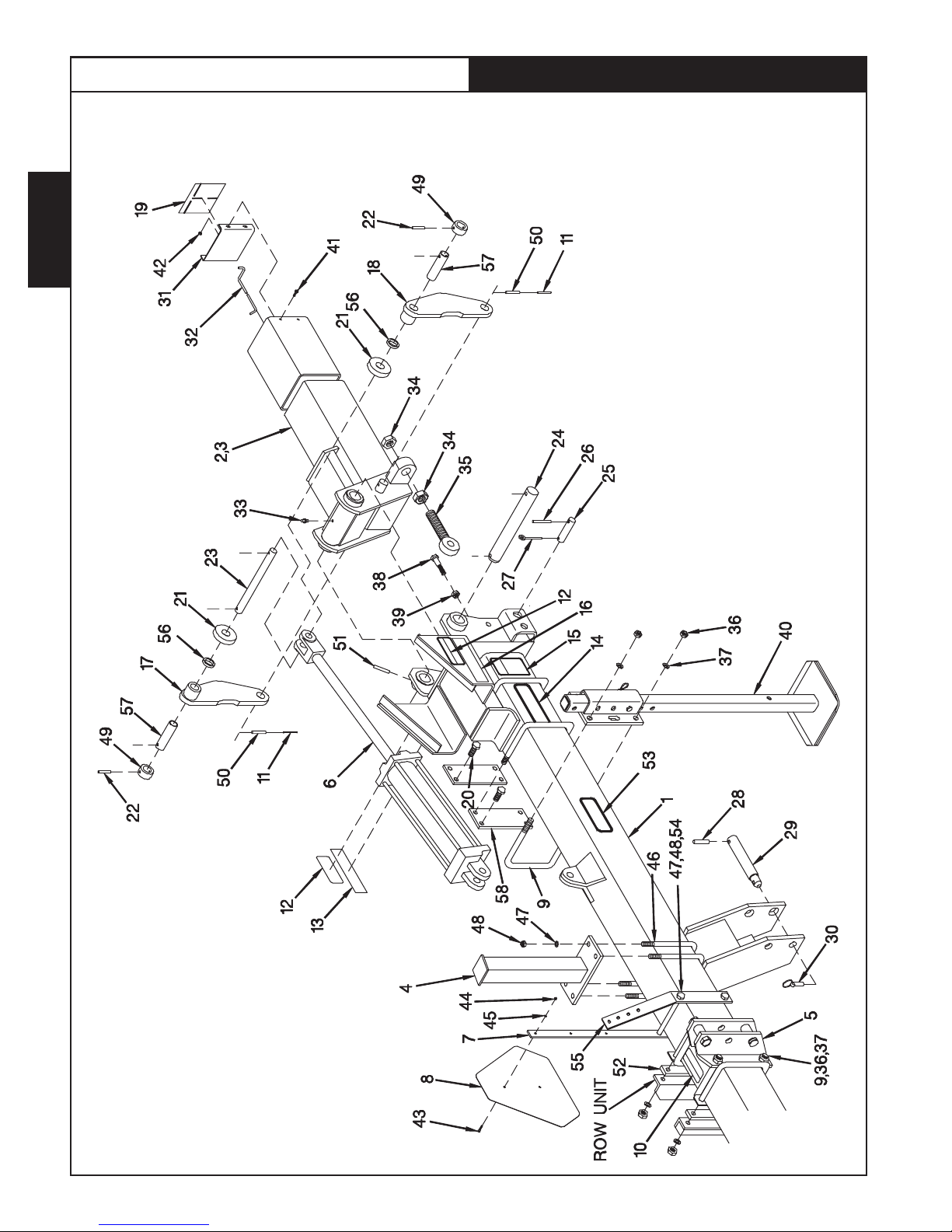
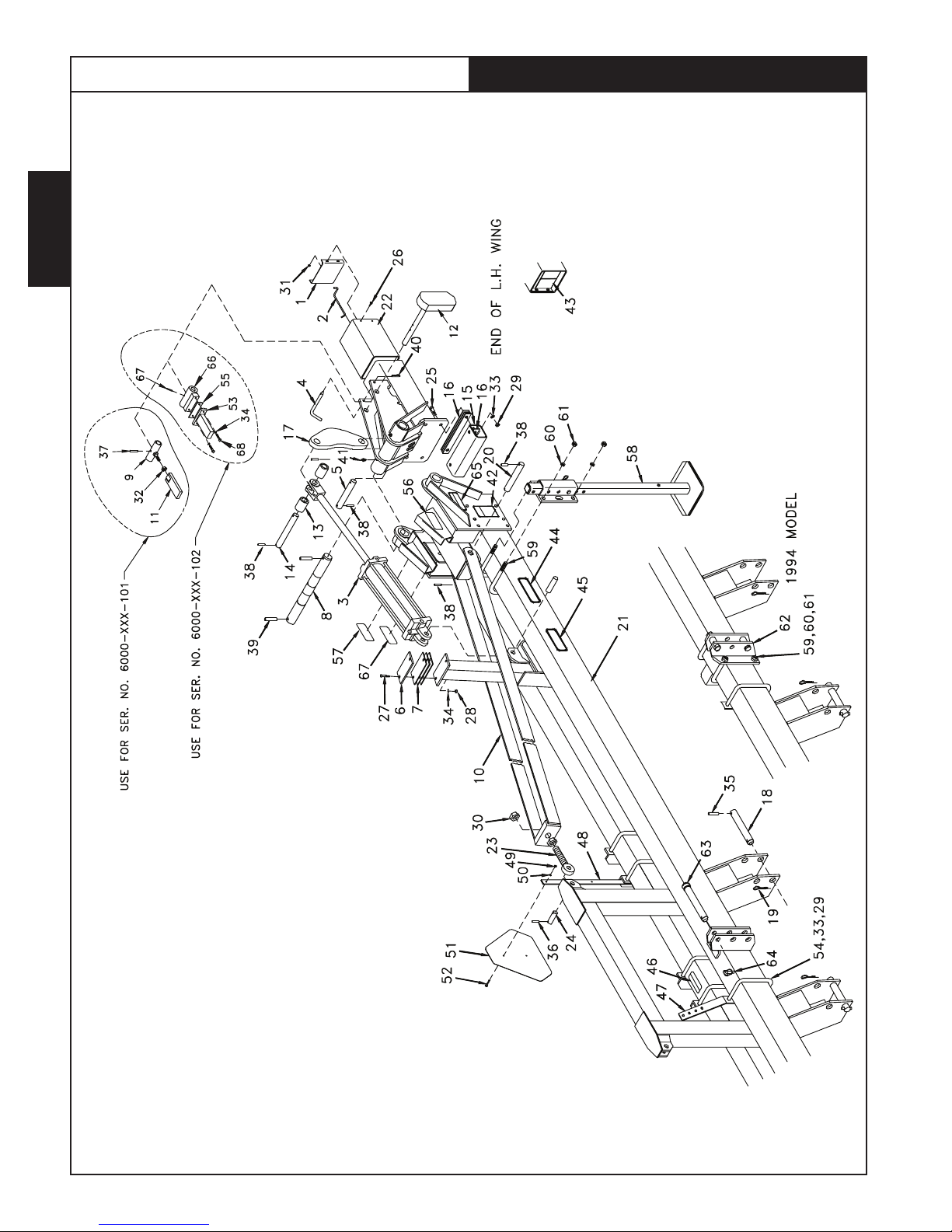
SERIES 6000 ROW CULTIVATOR
FOLDING TOOLBAR ASSEMBLY
SERIAL NO. ENDING 101 OR HIGHER
8 ROW 30
Page 4
DWG. N O. 3006
11/1 0

SERIES 6000 ROW CULTIVATOR
REF.
NO.
1
2
3
4
5
6
7
8
9
10
11
12
13
14
15
16
17
18
19
20
21
22
23
24
25
26
27
28
29
30
31
32
33
PART
NUMBER
810-001-284
810-001-475
81002580
952-001-007
81004234
81004235
81004236
81004406
953-003-002
81004351
81004482
81004481
81004436
81004437
81004296
81004297
81004298
81004300
81004301
953-003-009
81004400
81004394
953-003-030
952-001-005
950-001-185
950-002-006
950-003-009
951-001-005
951-001-008
955-001-001
951-002-002
81004251
81004287
DESCRIPTION QTY.
End Plate
Block Removing Rod
Cylinder Assembly 3 1/2 x 16 (See Sec. 3 Pg. 3)
Lock Washer 3/8 Inch
Pin
Rubber Cushion
Stand Shim
Hinge Pin
Spring Pin 1/2 x 2 1/2
Bushing
Top Link Pin
Linch Pin
Roller
Pin
Stop
Shim
Lift Link
Lower Hitch Pin
Clinch Pln
Spring Pin 3/8 x 1 3/4
Center Toolbar Weldment 8/30
Wing Toolbar Weldment 8/30
Spring Pin 1/2 x 3
Lock Washer 5/8 Inch
Hex Head Cap Screw 5/8-11 x 2 1/4 Gr. 5
Hex Head Flanged Whiz Lock Bolt 5/16-18 x 3/4
Carriage Bolt 3/8-16 x 1 3/4 Gr. 2
Hex Nut 3/8-16
Hex Nut 5/8-11
Grease Fitting 1/8-27 NPT
Flat Whiz Lock Nut 5/16-18
Pivot Weldment
Weight Weldment
10
REF.
NO.
2
1
2
8
2
2
6
2
2
2
1
1
4
2
2
2
2
2
8
1
2
4
6
4
8
4
4
6
2
8
2
2
34
953-003-006
35
951-002-052
36
81004284
37
81003042
38
953-005-001
39
810-001-920
40
875-001-038
41
952-001-006
42
951-001-009
43
952-001-001
44
951-001-003
45
850-002-426
46
81004129
47
81004136
48
850-001-306
49
850-001-980
50
850-001-285
51
850-001-305
52
810-001-473
81004309
53
81004700
54
701-30022
55
950-001-108
56
81004697
57
81004695
58
850-001-354
59
815-001-004
60
805-001-784
61
805-001-332
62
950-001-003
PART
NUMBER
DESCRIPTION QTY.
Spring Pin 1/4 x 1 1/2
Jam Nut 3/4-10
Latch Weldment
Pin
Hair Pin Cotter .120 x 2 3/8
Parking Stand Assembly (Includes Items 40, 41,
42) (See Sec. 4 Pg. 6)
U-Bolt Plated
Lock Washer 3/4 Inch
Hex Nut 3/4-10
Lock Washer 1/4 Inch Med Split SAE
Hex Nut 1/4-20
Decal Caution
Decal 6000 Series
Decal Hiniker
Decal Lift Cylinder
Decal Warning
Tape-Yellow Reflector
Tape-Red Reflector
Decal Notice
Decal Bag (Includes Items 45, 46, 47, 48, 49,
50, 51 & 52)
Tube Weldment
Spring Pin 3/16 x 2
Hex Bolt 3/8-16 x 1 1/2
Lock Bar Weldment
Shim
SMV Sign
SMV Strap
30° Bulkhead Plate
U-Bolt 5/8
Hex Head Cap Screw 1/4-20 x 1 Gr. 2
2
2
2
2
2
2
4
8
8
2
2
1
2
2
2
4
2
2
1
1
2
2
4
2
A/R
1
1
1
1
2
S
E
C
2
11/1 0
Page 5
S
E
C
2
SERIES 6000 ROW CULTIVATOR
FOLDING TOOLBAR ASSEMBLY
SERIAL NO. ENDING 100
8 ROW/36-38, 12 ROW/30
Page 6
DWG. N O. 2890
11/1 0
SERIES 6000 ROW CULTIVATOR
REF.
NO.
1
2
3
4
5
6
7
8
9
10
11
12
13
14
15
16
17
18
19
20
21
22
23
24
25
26
27
28
PART
NUMBER
810-002-132
810-002.338
810-002-133
810-002-349
810-002-134
810-002-350
810-002-164
81004129
810-002-085
81004342
815-001-004
850-001-354
875-001-038
850-002-426
701-30004
850-001-980
850-001-305
81004136
850-001-306
850-001-285
810-002-157
810-002-156
810-001-473
950-001-087
810-001-255
953-003-017
81002603
810-002-155
850-001-200
953-003-023
953-005-002
953-003-002
DESCRIPTION QTY.
Center Frame Weldment (12/30)
Center Frame Weldment (8/36-38)
LH Wing Weldment (12/30)
LH Wing Weldment (8/36-38)
RH Wing Weldment (12/30)
RH Wing Weldment (8/36-38)
Stand Weldment 12/30
Stand Weldment 8/36-38
Upper Hitch Assembly (Includes Items 9, 37 &
37) (See Sec. 4 Pg. 7)
4 x16 Diameter Cylinder SAE (See Sec. 3 Pg. 4)
SMV Mount Strap
SMV Sign
3/4 U-Bolt
Caution Decal
Spring Pin 3/16 x 2 1/4
Warning Decal
Tape Reflector (Red)
Hiniker Decal
Warning Decal
Tape Reflector (Yellow)
LH Link Weldment
RH Link Weldment
Notice Decal
Hex Head Cap Screw 5/8 x 1 1/2 (8 Row 36 Only)
Roller
Spring Pin 5/16 x 2
Link Pin
Hinge Pin
Hinge Pin
Spring Pin 5/16 x 3
Hair Pin Cotter .178 x 3 9/16
Spring Pin 1/2 x 2 1/2
REF.
NO.
1
1
1
1
1
1
2
2
1
2
1
1
6
1
4
4
2
2
2
2
2
2
1
8
4
4
2
2
2
2
2
2
29
810-002-485
30
230-026-005
31
810-001-284
32
810-001-475
33
955-001-001
34
951-001-022
35
850-002-503
36
951-001-009
37
952-001-006
38
950-001-031
39
951-005-052
40
810-001-920
41
950-002-006
42
951-002-002
43
950-001-003
44
951-001-003
45
952-001-001
46
805-001-332
47
952-001-005
48
951-001-008
49
81003138
50
953-003-008
51
953-003-028
52
81004186
53
81004129
81004182
54
950-001-181
55
805-001-784
56
845-001-150
57
81002674
58
810-002-371
PART
NUMBER
DESCRIPTION QTY.
Lower Hitch Pin
Klik Pin
End Cover
Block Removing Rod
Grease Fitting
Hex Nut 1 1/4
Eye Bolt 1 1/4
Hex Nut 3/4-10
Lock Washer 3/4 Inch
Hex Bolt 3/4-10 x 3
Jam Nut 3/4-10
Parking Stand Assembly (Includes Items 9, 36
& 37) (See Sec. 4 Pg. 6)
Hex Head Flanged Whiz Lock Bolt 5/16 x 3/4
Whiz Lock Nut 5/16
Hex Head Cap Screw 1/4-20 x 1
Hex Nut 1/4
Lock Washer 1/4 Inch
U-Bolt 5/8
Lock Washer 5/8 Inch
Hex Nut 5/8
Roller
Spring Pin 5/16 x 2 1/4
Spring Pin 1/2 x 2 3/4
Spacer Straps
6000 Decal
Decal Bag (Includes Items 10, 12, 13, 14, 15,
16, 19 & 53)
Hex Head Cap Screw 5/8-11 x 8 1/2 Gr. 5
30° Bulkhead Plate
Spacer
Tube
Spacer Plate (8 Row 36 Only)
12
12
2
2
2
1
S
2
E
4
C
2
2
4
4
2
B
8
2
2
2
4
8
8
4
4
2
2
2
1
2
1
4
4
4
11/1 0
Page 7
S
E
C
2
SERIES 6000 ROW CULTIVATOR
FOLDING TOOLBAR ASSEMBLY
SERIAL NO. ENDING 101 OR HIGHER
8 ROW 36-38-40,10 ROW 30, 12 ROW 30
Page 8
DWG. N O. 3010
11/1 0

REF.
NO.
1
2
3
4
5
6
7
8
9
10
11
12
13
14
15
16
17
18
19
20
21
22
23
24
25
26
27
28
29
30
31
PART
NUMBER
810-001-284
810-001-475
81004342
952-001-007
81004234
81004235
81004236
61004406
952-001-005
81004481
81004482
953-003-002
81004289
81004290
81004296
81004297
81004298
81004300
81004301
953-003-009
81004401
81004402
81004393
81004392
953-003-030
951-002-002
950-001-185
950-002-006
950-003-009
951-001-005
951-001-008
955-001-001
81004251
DESCRIPTION QTY.
End Plate
Block Removing Rod
Cylinder Assembly 4 x 16 (Sec 3 Page 5)
Lock Washer 3/8 Inch Medium Split SAE
Pin
Rubber Cushion
Stand Shim
Hinge Pin
Lock Washer 5/8 Inch Medium Split SAE
Linch Pin
Top Link Pin
Spring Pin 1/2 x 2-1/2
Roller
Pin
Stop
Shim
Lift Link
Lower Hitch Pin
Clinch Pin
Spring Pin 3/8 x 1-3/4
Center Toolbar Weldment 8/36-38-40
Center Toolbar Weldment 12/30
Wing Toolbar Weldment 8/36-38-40
Wing Toolbar Weldment 12/30
Spring Pin 1/2 x 3
Flanged Whiz Lock Nut 5/16-18
Hex Head Cap Screw 5/18-11 x 2 1/4 Gr. 5
Hex Head Flanged Whiz Lock Bolt 5/16-18
Carriage Bolt 3/8-16 x 1-3/4 Gr. 2
Hex Nut 3/8-16
Hex Nut 5/8-11
Grease Fitting 1/8-27 NPT
Pivot Weldment
10
SERIES 6000 ROW CULTIVATOR
REF.
NO.
2
1
2
8
2
2
6
2
6
1
1
2
4
2
2
2
2
2
8
1
1
2
2
4
8
4
8
4
4
6
2
2
32
81004702
33
953-003-006
34
951-005-052
35
81004284
36
81003042
37
953-005-001
38
810-001-920
39
875-001-038
40
952-001-006
41
951-001-009
42
952-001-005
43
951-001-003
44
850-002-426
45
81004129
46
81004136
47
850-001-306
48
850-001-980
49
850-001-285
50
850-001-305
51
810-001-473
81004309
52
850-001-354
53
815-001-004
54
805-001-784
55
805-001-332
56
81004700
57
701-30022
58
950-001-108
59
81004697
60
81004695
61
950-001-003
PART
NUMBER
DESCRIPTION QTY.
Weight Weldment
Spring Pin 1/4 x 1-1/2
Jam Nut 3/4-10
Latch Weldment
Pin
Hair Pin Cotter .120 x 3 3/8
Parking Stand Assembly (Includes Items 39,
40, 41)
U-Bolt Plated
Lock Washer 3/4 Inch Medium Split SAE
Hex Nut 3/4-10
Lock Washer 1/4 Medium Split SAE
Hex Nut 1/4-20
Decal Caution
Decal 6000 Series
Decal Hiniker
Decal Lift Cylinder
Decal Warning
Tape-Yellow Reflector
Tape-Red Reflector
Decal-Notice
Decal Bag (Includes Items 44, 45, 46, 47, 48,
49, 50 & 51)
SMV Sign
SMV Strap
30° Bulkhead Plate
U-Bolt 5/8
Tube Weldment
Spring Pin 3/16 x 2
Hex Head Cap Screw 3/8-16 x 1 1/2
Lockbar Weldment
Shim
Hex Head Cap Screw 1/4-20 x 1 Gr. 2
2
2
2
2
2
2
2
2
2
2
2
2
1
2
2
2
4
2
2
1
1
1
1
1
1
2
2
4
2
A/R
2
S
E
C
2
11/1 0
Page 9
S
E
C
2
SERIES 6000 ROW CULTIVATOR
FOLDING TOOLBAR ASSEMBLY
SERIAL NO. ENDING 100 OR HIGHER
12 ROW 36/38 & 16 ROW 30, 18 ROW 28
Page 10
DWG. N O. 3020
11/1 0
REF.
NO.
1
2
3
4
5
6
7
8
9
1D
11
12
13
14
15
16
17
18
19
20
21
22
23
24
25
26
27
28
29
30
31
32
33
PART
NUMBER
810-001-284
810-001-475
81002581
81004872
81003042
81004234
81004235
81004236
81004246
81004251
81004257
81004304
81004284
81004702
81004289
81004290
81004296
81004297
81004298
81004300
81004301
81004302
81004306
81004305
81004308
81004307
81004852
81004853
850-002-503
865-001-042
950-001-185
950-002-006
030-16071
951-001-005
951 001-008
951-001-022
951-002-002
951-005-052
952-001-005
DESCRIPTION QTY.
End Plate
Block Removing Rod
Cylinder Assembly 5 x 16 (Sec 3 Page 6)
Cylinder Assembly 5 x 16 (Sec 3 Page 6)
Pin
Pin
Rubber Cushion
Stand Shim
Hinge Pin
Pivot Weldment
Strap Weldment (16 Row 30) (18 ROW 28)
Strap Weldment (12 Row 36/38)
Latch Weldment
Weight Weldment
Roller
Pin
Stop
Shim
Lift Link
Lower Hitch Pin
Clinch Pin
Pin
Center Toolbar Weldment 12/36-38
Center Toolbar Weldment 16/30 & 18/28
Wing Toolbar Weldment 12/36-38
Wing Toolbar Weldment 16/30
Left Wing Toolbar Weldment 18/28
Right Wing Toolbar Weldment 18/28
Eye Bolt 1 1/4-7
Control Arm Link Pin
Hex Head Cap Screw 5/8-11 x 2-1/4 Gr. 5
Hex Head Flanged Whiz Lock Bolt 5/16-18 x 3/4
Carriage Bolt 3/8-16 x 1 3/4 Gr. 5
Hex Nut 3/8-16
Hex Nut 5/8-11
Hex Nut 1 1/4-7
Hex Head Flanged Whiz Lock Nut 5/16-18
Jam Nut 3/4-10
Lock Washer 5/8 Inch
10
SERIES 6000 ROW CULTIVATOR
REF.
NO.
2
1
2
2
2
2
2
6
2
2
2
2
2
2
4
2
2
2
2
2
2
1
1
2
2
1
1
2
2
4
8
4
4
6
4
8
2
6
34
952-001-007
35
953-003-002
36
953-003-003
37
953-003-006
38
953-003-009
39
953-003-030
40
953-005-001
41
955-001-001
42
850-001-036
43
810-001-473
44
81004136
45
81004129
46
850-002-426
47
805-001-784
48
815-001-004
49
951-001-003
50
952-001-001
51
850-001-354
52
950-001-003
53
81004697
54
81003020
55
81004695
56
850-001-285
57
850-001-305
58
81004311
59
875-001-035
60
952-001-006
61
951-001-009
62
81004237
63
81004482
64
81004481
65
850 001-980
81004309
66
81004700
67
701-30022
68
950-001-108
PART
NUMBER
DESCRIPTION QTY.
Lock Washer 3/8 Inch
Spring Pin 1/2 x 2 1/2
Spring Pin 1/4 x 1 3/4
Spring Pin 1/4 x 1 1/2
Spring Pin 3/8 x 1 3/4
Spring Pin 1/2 x 3
Hair Pin Cotter .120 x 2 3/8
Grease Fitting 1/8-27 NPT
Warning Decal
Notice Decal
Hiniker Decal
6000 Decal
Caution Decal
30° Bulk Head Plate
SMV Mount Strap
Hex Nut 1/4-20
Lock Washer 1/4 Inch
SMV Sign
Hex Head Cap Screw 1/4-20 x 1
Lockbar Weldment
U-Bolt 5/8
Shim
Tape Yellow Reflective
Tape Red Reflective
Parking Stand Assembly (Sec 4 Page 6)
U-Bolt 3/4
Lock Washer 3/4 Inch
Hex Nut 3/4-10
Upper Hitch Assembly (Includes Items 61, 62
& 63)
Top Link Pin Cat III
Linch Pin
Decal Warning
Decal Bag (Includes Items 42, 43, 44, 45,46,
57, 58, 59 & 67)
Tube Weldment
Spring Pin 3/16 x 2
Hex Bolt 3/8-16 x 1 1/2
8
2
4
2
12
4
2
4
2
1
2
2
1
1
1
2
2
1
2
2
1
A/R
2
2
2
A/R
A/R
A/R
1
1
1
4
2
2
4
S
E
C
2
11/1 0
Page 11

SERIES 6000 ROW CULTIVATOR
SECTION 3
HYDRAULICS
PAGE 2 HYDRAULIC PLUMBING
170 DEGREE WING LIFT ALL FOLDING MODELS
WING LIFT CYLINDERS
PAGE 3 PRINCE 3.5 INCH DIA. X 16 INCH STROKE
PAGE 4 PRINCE 4.00 INCH DIA. X 16 INCH STROKE P/N AM-111SP
PAGE 5 PRINCE 4.00 INCH DIA. X 16 INCH STROKE P/N AR-264
PAGE 6 PRINCE 5.00 INCH DIA. X 16 INCH STROKE
LIFT ASSIST CYLINDERS
PAGE 7 TEXAS HYD. 3.00 INCH DIA. X 8 INCH STROKE
S
E
C
3
PAGE 8 PRINCE 3.00 INCH DIA. X 8 INCH STROKE
11/1 0
Page 1
S
E
C
3
SERIES 6000 ROW CULTIVATOR
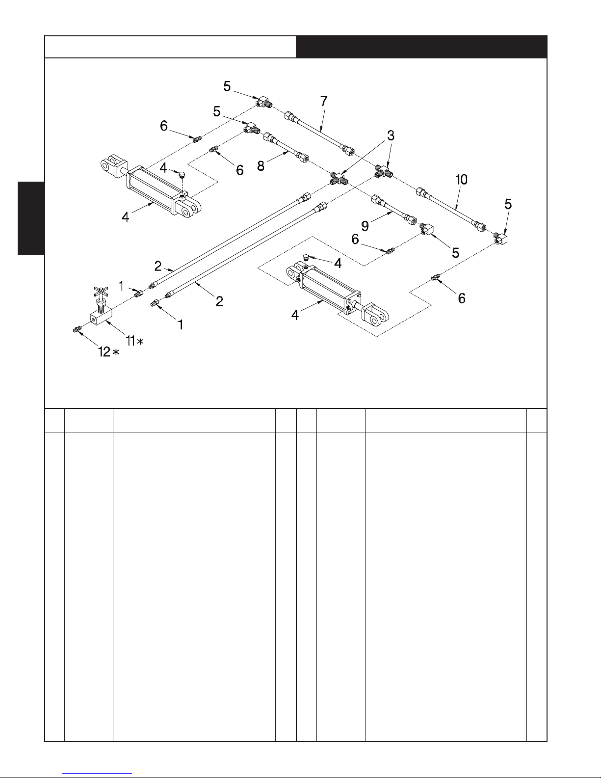
HYDRAULIC PLUMBING 170 DEGREE WING LIFT
*NOTE: TO HAVE POSITIVE LOCK ON TOOLBAR WING LOCK, AN OPTIONAL NEEDLE VALVE IS OFFERED NO. 81004701.
THIS WILL INSURE THE LIFT CYLINDER WILL NOT CLOSE, AND DISENGAGE WING LOCK.
DWG. N O. 3215
REF.
NO.
Page 2
NUMBER
1
956-004-002
2
957-002-014
3
956-007-003
4
81002580
81004342
81004872
5
956-005-002
6
956-008-024
956-008-025
7
957-001-009
957-001-017
957-001-018
957-001-021
957-001-056
8
957-001-004
957-001-009
PART
DESCRIPTION QTY.
Reducer Bushing 1/2 Male NPT to 3/8 Female
NPT
3/8 Inch Hose Assembly 48 Inches
Bulkhead Tee 9/16 Male JIC To 9/16 Male JIC
To 9/15 Male JIC
3.50 Inch Diameter x 16 Inch Stroke Cylinder
8 Row 30
4.00 Inch Diameter x 16 Inch Stroke Cylinder 8
Row 36-38-40, 10 Row 30, 12 Row 30
5.00 Inch Diameter x 16 Inch Stroke Cylinder
10 Row 36-38, 12 Row 36-38, 16 Row 30, 18
Row 28
90° Elbow 9/16 Female JIC to 9/16 Male JIC
Restrictor Fitting 3/4 Male SAE O-Ring to 9/16
Male JIC 3.50 & 4.00 Cylinder
Restrictor Fitting 7/8 Male SAE O-Ring to 9/16
Male JIC 5.00 Cylinder
3/8 Inch Hose Assembly 50 Inch 8 Row 30
3/8 Inch Hose Assembly 72 Inch 8 Row 3638-40
3/8 Inch Hose Assembly 79 Inch 10 Row 30,
12 Row 30
3/8 Inch Hose Assembly 102 Inch 10 Row 3638, 12 Row 36-38
3/8 Inch Hose Assembly 108 Inch 16 Row 30
& 18 Row 28
3/8 Inch Hose Assembly 29 inch 8 Row 30
3/8 Inch Hose Assembly 50 inch 8 Row 36,
38,40
2
2
2
2
2
2
4
4
4
1
1
1
1
1
1
1
11/1 0
REF.
NO.
8
9
10
11
12
PART
NUMBER
957-001-014
957-001-057
957-001-019
957-001-006
957-001-015
957-001-018
957-001-021
957-001-056
957-001-014
957-001-057
957-001-020
957-001-054
957-001-023
81004701
956-003-022
DESCRIPTION QTY.
3/8 Inch Hose Assembly 60 Inch 10 Row 30,
12 Row 30
3/8 Inch Hose Assembly 86 Inch 10 Row 36,
38, 12 Row 36, 38
3/8 inch Hose Assembly 92 inch 16 Row 30
18 Row 28
3/8 Inch Hose Assembly 41 Inch 8 Row 30
& Row 28
3/8 inch Hose Assembly 68 Inch 8 Row 36,
38,40
3/8 Inch Hose Assembly 79 Inch 10 Row 30,
12 Row 30
3/8 Inch Hose Assembly 102 Inch 10 Row
36,38, 12 Row 36, 38
3/8 Inch Hose Assembly 108 inch 16 Row
30 & 18 Row 28
3/8 Inch Hose Assembly 60 Inch 8 Row 30
3/8 Inch Hose Assembly 86 Inch 8 Row 36,
38,40
3/8 Inch Hose Assembly 96 Inch 10 Row 30,
12 Row 30
3/8 Inch Hose Assembly 120 Inch 10 Row
36, 38, 12 Row 36, 38
3/8 Inch Hose Assembly 126 Inch 16 Row
30 &18 Row 28
3/8 Needle Valve (Optional)
Straight Adapter 3/8 MNPT to 1/2 MNPT
(Optional)
1
1
1
1
1
1
1
1
1
1
1
1
1
1
1
SERIES 6000 ROW CULTIVATOR
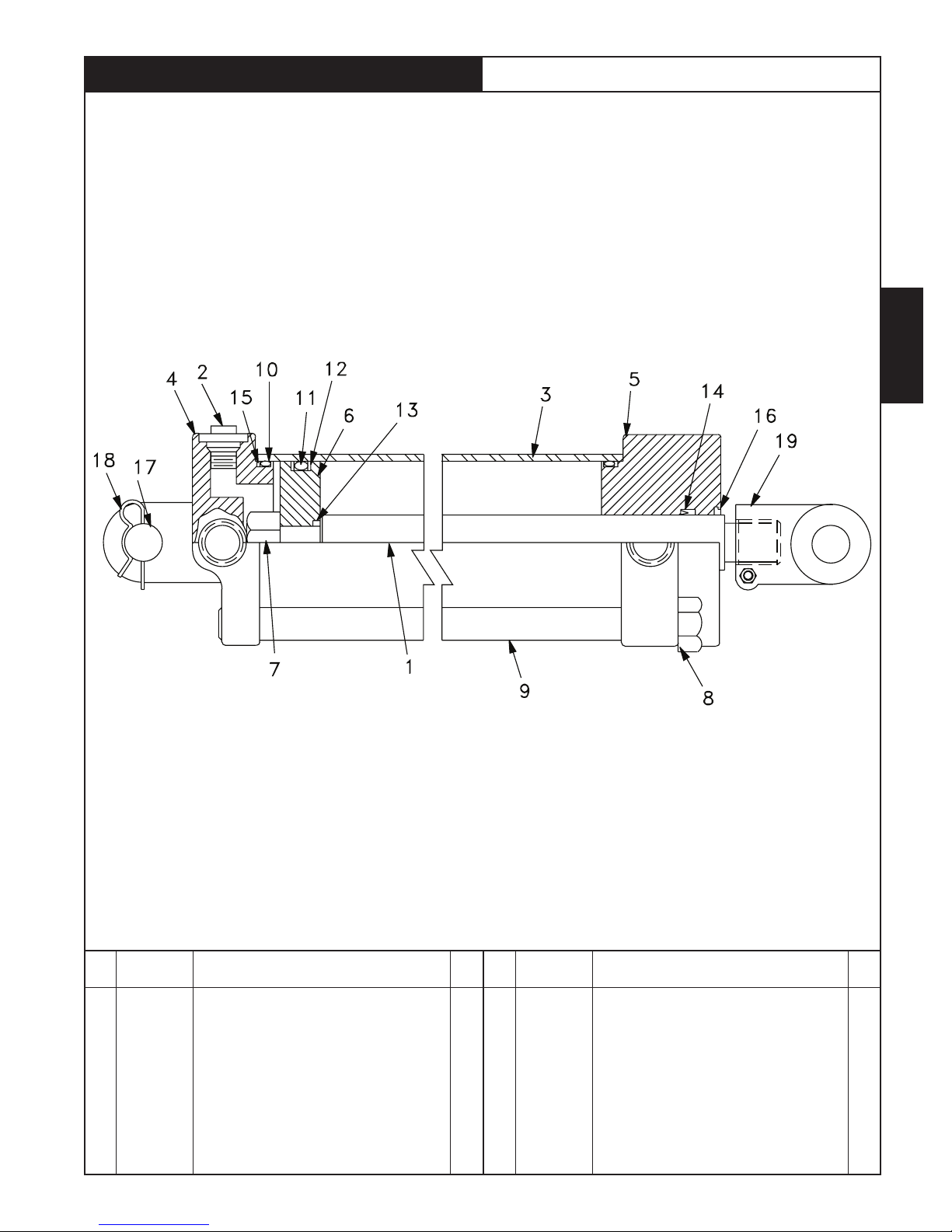
PRINCE 3.5 INCH DIAMETER X 16 INCH STROKE
CYLINDER 3/4 O-RING PORTS
S
E
C
3
Cylind er Identificatio n Hiniker P/N 81 002580
Prince Pin SAE-9316A-5 P
REF.
NO.
1
81002605
2
855-001-404
3
850-001-794
4
855-001-413
5
856-001-252
6
81002604
7
855-001-387
8
856-001-254
9
850-001-796
10
*
11
*
PART
NUMBER
DESCRIPTION QTY.
Piston Rod
#8 SAE Plug
Tube
Butt
Gland
Piston
Lock Nut 7/8-14 Uni-Torque
Hex Nut
Tie Rod
O-Ring
O-Ring
1
1
1
1
1
1
1
4
4
2
1
11/1 0
REF.
NO.
12
13
14
15
16
17
18
19
PART
NUMBER
*
*
*
*
*
850-001-804
840-001-206
856-001-239
856-001-258
81002580
DWG. N O. 2301
DESCRIPTION QTY.
Backup Washer
O-Ring
U-Cup
Backup Washer
Wiper
Clevis Pin
Hair Pin Clip
Clevis Assembly
Seal Kit Includes Items 10, 11, 12, 13, 14, 15 & 16
Complete 3 1/2 x 16 Cylinder Assembly
*NOTE: Items marked “*” are available in seal kit.
2
1
1
2
1
1
2
1
Page 3
 Loading...