

Page 1

ATevo SERIES BATTERY CHARGER
AT SERIES BATTERY CHARGER
PRODUCT
OPERATING & SERVICE
INSTRUCTIONS
Microprocessor-Controlled Float Battery Charger
SINGLE PHASE INPUT - GROUP I (6-25 Adc)
JA5011-51
Page 2

User Notes
Page 3

Manufacturer's Warranty
FIVE-YEAR
WARRANTY
[applies only to product(s) delivered within United States and Canada]
Product Details:
Battery Charger Model:
Factory Ordering Code:
Battery Charger Serial Number:
Date Shipped:
Date Energized:
Standard Warranty
This product is warranted to be free from defects in material and
workmanship for a period of five (5) years from date of manufacture.
During the term of the warranty period: parts, assemblies, or
components deemed to be defective will be repaired or replaced at the
manufacturer’s option, free of charge. All costs related to removal,
reinstallation and transportation will be paid by the purchaser/
customer and/or operator of the product. Evaluation, repair and/or
replacement of any defective part(s) are FOB manufacturer’s factory.
This warranty does not cover products or parts that are damaged from
improper use or abuse, as determined by the manufacturer. Accessory
items or additional items carry only their respective manufacturer’s
warranty. Consumable items (such as fuses and electrolytic
capacitors), which wear out under normal use are specifically not
covered by this standard warranty. Any consequential damage due
to diagnosis or repair by any party other than the manufacturer’s
authorized personnel is not covered under this warranty.
ATevo
iii
Page 4

Manufacturer's Warranty
Extended Spare Parts Warranty
The manufacturer’s extended warranty includes all items as mentioned
in the ‘Standard Warranty’ as previously listed, plus reasonable in/
out freight costs related to a warranty claim for parts. Said freight
cost is based on either standard UPS rates or common carrier only, as
appropriate. Contact your sales representative for more information
& pricing regarding the extended spare parts warranty.
Magnetic Parts 25-Year Extended Warranty
(equal to 5% of the original purchase price)
Lifetime warranty (limited to 25 years from date of shipment) covers
battery charger major electromagnetic components (T1 transformer,
L1 inductor & L2 inductor) as applicable. Coverage is for 100%
replacement of any covered magnetic component that fails during
normal use. Abuse, neglect, and damage from outside sources
or improper application will make this warranty null and void. The
manufacturer reserves the right to make final determination regarding
the application of this warranty. The manufacturer will be responsible
for costs related to inbound and outbound freight of warranted
magnetic components (T1, L1 & L2).
Freight cost is based on standard UPS rates or common carrier only,
as appropriate. Costs related to removal and/or reinstallation of
warranted magnetic components will be the responsibility of the
purchaser/customer and/or operator of the product. Contact your
sales representative for more information & pricing regarding the
magnetic parts extended warranty.
NOTICE Requests for returns or warranty claims
via manufacturer’s Return Material Authorization (RMA) instructions and
assignment. Contact your sales representative for more information &
pricing regarding returns or warranty claims. Returns that do not follow
this procedure will not be honored.
Election to any of the above offered extended warranties must be done
within the terms of the initial standard warranty.
iv
ATevo
must
be made
Page 5
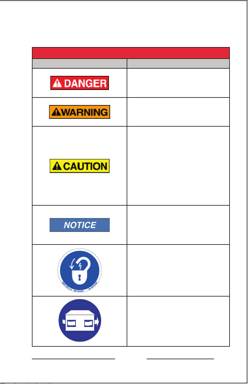
SAFETY INSTRUCTIONS
PLEASE READ AND FOLLOW TO AVOID
SERIOUS INJURY OR DEATH
EQUIPMENT/MANUAL SAFETY WARNINGS
WARNING MEANING
Imminently hazardous situation,
which if not avoided, WILL
result in death or serious injury.
Potentially hazardous situation,
which if not avoided, could
result in death or serious injury.
Potentially hazardous situation,
which if not avoided, could
result in minor or moderate
injury (e.g. minor burns,
bruising from pinch points,
minor chemical irritation).
May also be used to alert
against unsafe practices.
ATevo
Important information not
related to personal injury (e.g.
messages related to equipment
or property damage).
LOCKOUT TAGOUT is required
before servicing.
VENTILATION MANDATORY.
Maintain at least 6in / 152mm
of free air on all vented surfaces
for cooling. Allow sufficient
clearance to open front panel
for servicing.
v
Page 6
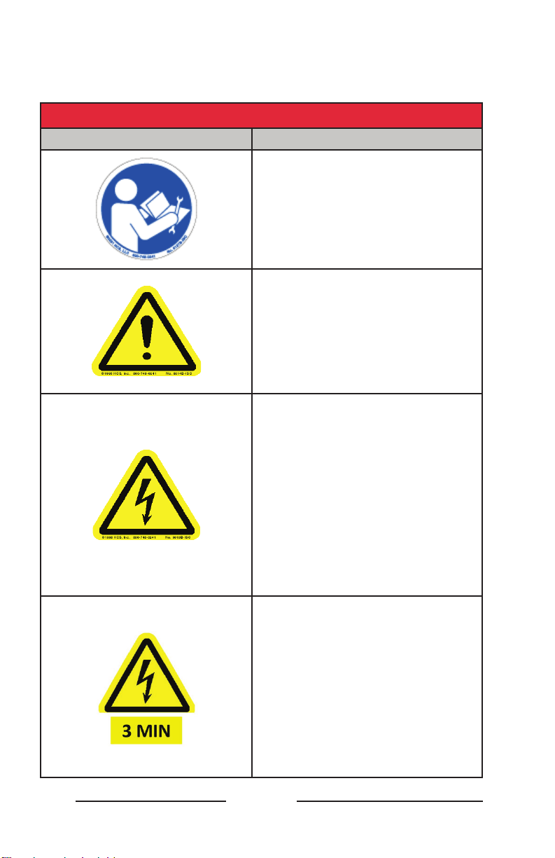
SAFETY INSTRUCTIONS
PLEASE READ AND FOLLOW TO AVOID
SERIOUS INJURY OR DEATH
EQUIPMENT/MANUAL SAFETY WARNINGS
WARNING MEANING
Refer to manual.
SAFETY ALERT. Indicates that a
hazardous situation exists. TO
REDUCE RISK OF INJURY OR
DEATH, refer to accompanying
documents, and follow all steps
or procedures as instructed.
DANGEROUS HIGH VOLTAGE
inside product enclosure.
TO REDUCE RISK OF FIRE
OR ELECTRIC SHOCK, do not
attempt to open enclosure or
gain access to areas where you
are not instructed to do so.
SERVICING IS TO BE DONE
ONLY BY QUALIFIED SERVICE
PERSONNEL.
vi
Allow at least 3 minutes
for internal components to
discharge to a safe level
after performing lockout
tagout to prevent exposure to
DANGEROUS HIGH VOLTAGE.
ATevo
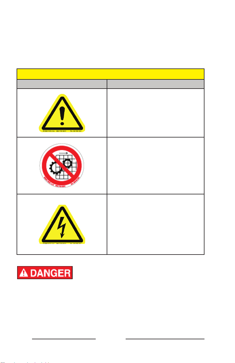
Page 7

SAFETY INSTRUCTIONS
PLEASE READ AND FOLLOW TO AVOID
SERIOUS INJURY OR DEATH
EQUIPMENT/MANUAL SAFETY WARNINGS
WARNING MEANING
DANGER! Risk of Arc Flash
(only for ATevo units with input
voltage over 416 Vac)
EXPLOSIVE GAS can be
produced from batteries during
normal operation.
Never smoke, use an open
flame, or create arcs in the
vicinity of the ATevo or the
battery.
Do not operate equipment
without all guards and/or
covers in place.
ATevo
vii
Page 8
SAFETY INSTRUCTIONS
PLEASE READ AND FOLLOW TO AVOID
SERIOUS INJURY OR DEATH
Use of equipment in a manner not specified by
manufacturer may impair protection provided by ATevo.
EXAMPLES OF EQUIPMENT MISUSE
SYMBOL EXAMPLE
Do not use the equipment for
any purpose not described in
this manual.
Do not operate this equipment
without all guards and covers in
place.
Do not operate this equipment
from any power source that
does not match voltage rating
stamped on equipment.
Refer to Manufacturer’s
Identification Label for
operational requirements.
1. Do not touch any uninsulated parts of ATevo, especially the
input and output connections, as there is the possibility of
electrical shock.
2. During normal operation, batteries may produce EXPLOSIVE
GAS! Never smoke, use an open flame, or create arcs in the
vicinity of ATevo, or the battery.
viii
ATevo
Page 9

SAFETY INSTRUCTIONS
PLEASE READ AND FOLLOW TO AVOID
SERIOUS INJURY OR DEATH
1. Before using ATevo, read all instructions and cautionary
markings on: a) this equipment, b) battery, and c) any other
equipment to be used in conjunction with ATevo
2. Do not use ATevo for ANY purpose not described in this manual.
3. Do not install ATevo outdoors, or in wet or damp locations,
unless specifically equipped for that environment.
4. Do not operate ATevo with any power source that does not
match the specified ac and dc voltage ratings. Refer to the data
nameplate decal affixed to the outside panel for operational
requirements.
5. Turn OFF ATevo before connecting or disconnecting the battery
to avoid electrical shock hazards, arcing, burning, and/or
equipment damage.
6. Do not operate ATevo with the safety shield or any other
supplied guards removed or improperly installed.
7. Do not operate ATevo if it has been damaged in any way. Refer
to qualified service personnel.
8. De-energize and lock out all ac and dc power sources to ATevo
before servicing.
9. Do not disassemble ATevo. Only qualified service personnel
should attempt repairs. Incorrect reassembly could result in
explosion, electrical shock or fire.
10. Remove all jewelry, watches, rings, etc. before proceeding with
installation or servicing to avoid electrical shock hazards.
1. This manual contains important safety and operating
instructions, and therefore should be filed for easy access.
2. Maintain at least 6in / 152mm of free air on all vented surfaces
for cooling. Allow sufficient clearance to open the front panel
for servicing.
ATevo
ix
Page 10

Table of Contents - ATevo
TABLE OF
CONTENTS (1PH 6-25 Adc - Group I)
MANUFACTURER’S WARRANTY � � � � � � � � � � � � � � � � � � � � � � � � � � � � � � � � � � � � � � � iii
SAFETY INSTRUCTIONS � � � � � � � � � � � � � � � � � � � � � � � � � � � � � � � � � � � � � � � � � � � � � � � v
1. RECEIVING & MOUNTING � � � � � � � � � � � � � � � � � � � � � � � � � � � � � � � � � � � � � � � � � � �2
1.1 Storing ATevo . . . . . . . . . . . . . . . . . . . . . . . . . . . . . . . . . . . . . . . . . 2
1.2 Receiving ATevo . . . . . . . . . . . . . . . . . . . . . . . . . . . . . . . . . . . . . . 2
1.3 Unpacking and Inspecting ATevo . . . . . . . . . . . . . . . . . . . . . . . . 2
1.3.1 Inspection Checklist
1.4 Reporting Damage or Shortage . . . . . . . . . . . . . . . . . . . . . . . . . 2
1.5 Returning Damaged Equipment . . . . . . . . . . . . . . . . . . . . . . . . . 3
1.6 Moving ATevo . . . . . . . . . . . . . . . . . . . . . . . . . . . . . . . . . . . . . . . . 3
1.6.1 ATevo Weight Table
1.7 Mounting ATevo . . . . . . . . . . . . . . . . . . . . . . . . . . . . . . . . . . . . . . 4
1.7.1 Wall-Mounting
1.7.2 Floor-Mounting
1.7.3 Rack-Mounting
� � � � � � � � � � � � � � � � � � � � � � � � � � � � � � � � � � � � �
� � � � � � � � � � � � � � � � � � � � � � � � � � � � � � � � � � � � �
� � � � � � � � � � � � � � � � � � � � � � � � � � � � � � � � � � � � � � � � �
� � � � � � � � � � � � � � � � � � � � � � � � � � � � � � � � � � � � � � � � �
� � � � � � � � � � � � � � � � � � � � � � � � � � � � � � � � � � � � � � � � �
2
3
4
6
8
2. WIRING � � � � � � � � � � � � � � � � � � � � � � � � � � � � � � � � � � � � � � � � � � � � � � � � � � � � � � � � � � � �10
2.1 Mechanical Diagram and Component Location . . . . . . . . . . 10
2.1.1 Main Control Board (A1)
2.1.2 Power Board (A2)
2.1.3 Auxiliary I/O Board (A4) - optional
2.1.4 Filter Capacitor Board (A7)
2.1.5 AC Surge Suppressor MOV Board (A9)
2.1.6 Serial Communications Adapter (A12) - optional
2.1.7 Forced Loasd Shating Adapter (A13) - optional
2.1.8 Ethernet Communications Adapter (A22) - optional
2.1.9 Eliminator Capacitor (C2) - optional
2.1.10 AC Input Circuit Breaker (CB1)
2.1.11 DC Output Circuit Breaker (CB2)
2.1.12 Main Filter Inductor (L1)
2.1.13 Secondary Filter Inductor (L2)
2.1.14 Power Isolation Transformer (T1)
x
� � � � � � � � � � � � � � � � � � � � � � � � � � � � � � � � �
� � � � � � � � � � � � � � � � � � � � � � � � � � � � � � � � � � � � � �
� � � � � � � � � � � � � � � � � � � � � � � � � �
� � � � � � � � � � � � � � � � � � � � � � � � � � � � � � �
� � � � � � � � � � � � � � � � � � � � � � �
� � � � � � � � � � � � � � � �
� � � � � � � � � � � � � � � � �
� � � � � � � � � � � � �
� � � � � � � � � � � � � � � � � � � � � � � � �
� � � � � � � � � � � � � � � � � � � � � � � � � � � �
� � � � � � � � � � � � � � � � � � � � � � � � � �
� � � � � � � � � � � � � � � � � � � � � � � � � � � � � � � �
� � � � � � � � � � � � � � � � � � � � � � � � � � � �
� � � � � � � � � � � � � � � � � � � � � � � � � �
ATevo
12
12
12
12
12
12
13
13
13
13
13
13
13
13
Page 11

Table of Contents - ATevo
2.2 Removing Safety Shield . . . . . . . . . . . . . . . . . . . . . . . . . . . . . . . 14
2.3 ATevo with Selectable Input Voltage - optional . . . . . . . . . . . . 14
2.3.1 Determining if Multi-Tap Option is Present
2.3.2 Verifying Multi-Tap AC Input Voltage Setting
2.3.3 Modifying Multi-Tap AC Input Voltage Setting
� � � � � � � � � � � � � � � � � � � �
� � � � � � � � � � � � � � � � � �
� � � � � � � � � � � � � � � � �
14
15
15
2.4 Making AC Input Connections . . . . . . . . . . . . . . . . . . . . . . . . . 16
2.5 Making DC Output Connections . . . . . . . . . . . . . . . . . . . . . . . 18
2.6 Remote Voltage Sense . . . . . . . . . . . . . . . . . . . . . . . . . . . . . . . . 20
2.7 Wiring ATevo Common Alarm. . . . . . . . . . . . . . . . . . . . . . . . . . 20
2.8 Wiring Relays on Auxiliary I/O Board . . . . . . . . . . . . . . . . . . . 21
2.9 Wiring Temperature Compensation Probe . . . . . . . . . . . . . . . 21
2.10 Wiring Serial Communications Adapters . . . . . . . . . . . . . . . 22
2.11 Wiring Ethernet Adapter . . . . . . . . . . . . . . . . . . . . . . . . . . . . . 22
3. CONTROLS & NAVIGATION � � � � � � � � � � � � � � � � � � � � � � � � � � � � � � � � � � � � � � � � 23
3.1 Front Panel Controls and Indicators . . . . . . . . . . . . . . . . . . . . 23
3.1.1 Main ATevo Display
3.1.2 Navigation and Control Button Group
3.1.3 Operation Modes and Methods Button Group
3.1.4 Alarm Section
3.1.5 Hindle Health System (HHS) Section
3.1.6 AC Input and DC Output Circuit Breakers
3.2 Display . . . . . . . . . . . . . . . . . . . . . . . . . . . . . . . . . . . . . . . . . . . . . 25
3.2.1 Home Screen
3.2.2 Configuration Screens
3.2.3 Status Screens
3.2.4 Hindle Health System Screens
3.3 Main Menu and Navigation . . . . . . . . . . . . . . . . . . . . . . . . . . . 27
3.3.1 MENU and ARROW Buttons
3.3.2 EDIT/ENTER Button
3.3.3 Navigation Conventions in This Manual
3.3.4 Escape (ESC) Button
� � � � � � � � � � � � � � � � � � � � � � � � � � � � � � � � � � � �
� � � � � � � � � � � � � � � � � � � � � � �
� � � � � � � � � � � � � � � � �
� � � � � � � � � � � � � � � � � � � � � � � � � � � � � � � � � � � � � � � �
� � � � � � � � � � � � � � � � � � � � � � � �
� � � � � � � � � � � � � � � � � � � �
� � � � � � � � � � � � � � � � � � � � � � � � � � � � � � � � � � � � � � � � �
� � � � � � � � � � � � � � � � � � � � � � � � � � � � � � � � � �
� � � � � � � � � � � � � � � � � � � � � � � � � � � � � � � � � � � � � � � �
� � � � � � � � � � � � � � � � � � � � � � � � � � � � �
� � � � � � � � � � � � � � � � � � � � � � � � � � � � � �
� � � � � � � � � � � � � � � � � � � � � � � � � � � � � � � � � � � �
� � � � � � � � � � � � � � � � � � � � � �
� � � � � � � � � � � � � � � � � � � � � � � � � � � � � � � � � � � �
24
24
24
24
24
24
25
26
26
26
27
28
29
30
4. STARTUP & CONFIGURATION � � � � � � � � � � � � � � � � � � � � � � � � � � � � � � � � � � � � � � �31
4.1 Startup . . . . . . . . . . . . . . . . . . . . . . . . . . . . . . . . . . . . . . . . . . . . . 31
4.1.1 Understanding Startup Sequence
4.1.2 Factory Settings Tables
4.1.3 Checking Installation
4.1.4 Starting Up
4.1.5 Home Screen
� � � � � � � � � � � � � � � � � � � � � � � � � � � � � � � � � � � � � � � � � �
� � � � � � � � � � � � � � � � � � � � � � � � � � � � � � � � � � � � � � � � �
� � � � � � � � � � � � � � � � � � � � � � � � � � � � � � � � � �
� � � � � � � � � � � � � � � � � � � � � � � � � � � � � � � � � � �
ATevo
� � � � � � � � � � � � � � � � � � � � � � � � � � �
31
31
36
36
36
xi
Page 12

Table of Contents - ATevo
4.2 Configuring Basic Set Points and Alarms . . . . . . . . . . . . . . . . 37
4.2.1. How to Configure General Parameter Settings
4.2.2 Setting Float Voltage
4.2.3 Setting Equalize Voltage
4.2.4 Setting Equalize Timer
4.2.5 Setting High DC Alarm Voltage
4.2.6 Setting Low DC Alarm Voltage
4.2.7 Setting Current Limit Level
� � � � � � � � � � � � � � � � � � � � � � � � � � � � � � � � � � �
� � � � � � � � � � � � � � � � � � � � � � � � � � � � � � � � �
� � � � � � � � � � � � � � � � � � � � � � � � � � � � � � � � � �
� � � � � � � � � � � � � � � � � � � � � � � � � � � �
� � � � � � � � � � � � � � � � � � � � � � � � � � � �
� � � � � � � � � � � � � � � � � � � � � � � � � � � � � � �
� � � � � � � � � � � � � � � � �
4.3 Configuring Advanced Set Points and Alarms . . . . . . . . . . . . 41
4.3.1 How to Configure Advanced Settings
4.3.2 Setting High Voltage Shutdown
4.3.3 Setting High Level Detect
4.3.4 Setting End of Discharge (EOD) Alarm
4.3.5 Setting Low Voltage Level Detect
4.3.6 Setting AC Ripple Alarm
4.3.7 Setting Positive (+) Ground Fault Sensitivity Level
4.3.8 Setting Negative (-) Ground Fault Sensitivity Level
4.3.9 Setting Battery Temperature Compensation
4.3.10 Setting Battery Type for Temperature Compensation
� � � � � � � � � � � � � � � � � � � � � � � � � � � � � � � �
� � � � � � � � � � � � � � � � � � � � � � � � � � � � � � � � �
� � � � � � � � � � � � � � � � � � � � � � � �
� � � � � � � � � � � � � � � � � � � � � � � � � � � �
� � � � � � � � � � � � � � � � � � � � � � �
� � � � � � � � � � � � � � � � � � � � � � � � � � �
� � � � � � � � � � � � � � �
� � � � � � � � � � � � � �
� � � � � � � � � � � � � � � � � � �
� � � � � � � � � � � �
4.4 Configuring System Settings . . . . . . . . . . . . . . . . . . . . . . . . . . . 45
4.4.1 How to Configure System Settings
4.4.2 Setting System Time
4.4.3 Setting System Date
4.4.4 Setting Display Backlight Control
4.4.5 Setting Display Contrast
4.4.6 Setting Display Backlight Intensity
4.4.7 Setting Display Reverse Image Control
� � � � � � � � � � � � � � � � � � � � � � � � � � � � � � � � � � � �
� � � � � � � � � � � � � � � � � � � � � � � � � � � � � � � � � � � �
� � � � � � � � � � � � � � � � � � � � � � � � � � � � � � � � �
� � � � � � � � � � � � � � � � � � � � � � � � � �
� � � � � � � � � � � � � � � � � � � � � � � � � �
� � � � � � � � � � � � � � � � � � � � � � � � � �
� � � � � � � � � � � � � � � � � � � � � �
4.5 Configuring Relays . . . . . . . . . . . . . . . . . . . . . . . . . . . . . . . . . . . 47
4.5.1 Configuring Common Alarm Relay
4.5.2 Configuring Auxiliary I/O Board Relays
� � � � � � � � � � � � � � � � � � � � � � � � �
� � � � � � � � � � � � � � � � � � � � � �
4.6 Disabling Alarms in Common Alarm List . . . . . . . . . . . . . . . . 49
4.7 Configuring Serial Communications Adapter . . . . . . . . . . . . . 50
4.8 Configuring Ethernet Communications Adapter . . . . . . . . . . 50
4.9 Enabling/Disabling High Level Detect . . . . . . . . . . . . . . . . . . . 51
37
38
38
39
39
39
40
41
41
42
42
42
43
43
43
44
44
45
45
46
46
46
47
47
47
49
5. BASIC OPERATION � � � � � � � � � � � � � � � � � � � � � � � � � � � � � � � � � � � � � � � � � � � � � � � � 52
5.1 ATevo Operating Modes . . . . . . . . . . . . . . . . . . . . . . . . . . . . . . 52
5.1.1 Changing Display Mode
5.1.2 Changing Charge Mode
5.1.3 Changing Equalize Method
5.1.4 Lamp Test & Display of Firmware Versions
5.1.5 Resetting Latched Relays (legacy method)
xii
� � � � � � � � � � � � � � � � � � � � � � � � � � � � � � � � �
� � � � � � � � � � � � � � � � � � � � � � � � � � � � � � � � �
� � � � � � � � � � � � � � � � � � � � � � � � � � � � � � �
� � � � � � � � � � � � � � � � � � � �
� � � � � � � � � � � � � � � � � � � �
ATevo
52
53
54
55
55
Page 13

Table of Contents - ATevo
5.2 High Voltage Shutdown . . . . . . . . . . . . . . . . . . . . . . . . . . . . . . . 55
5.3 Low Level Detect . . . . . . . . . . . . . . . . . . . . . . . . . . . . . . . . . . . . . 56
5.4 High Level Detect . . . . . . . . . . . . . . . . . . . . . . . . . . . . . . . . . . . . 57
6. ADVANCED OPERATION � � � � � � � � � � � � � � � � � � � � � � � � � � � � � � � � � � � � � � � � � � � 58
6.1 ATevo Main Menu . . . . . . . . . . . . . . . . . . . . . . . . . . . . . . . . . . . . 58
6.1.1 Basic Settings Icon
6.1.2 Advanced Settings Icon
6.1.3 Save|Reset Configuration Icon
6.1.4 Event Logs Icon
6.1.5 Common Alarm Icon
6.1.6 Relays Icon
6.1.7 AUX Inputs Icon
6.1.8 Testing Icon
6.1.9 Communication Icon
6.1.10 Security Icon
6.1.11 System Settings Icon
6.1.12 System Information Icon
6.2 Alarms Button . . . . . . . . . . . . . . . . . . . . . . . . . . . . . . . . . . . . . . . 61
6.3 Health Button . . . . . . . . . . . . . . . . . . . . . . . . . . . . . . . . . . . . . . . 61
6.4 Security and Passwords . . . . . . . . . . . . . . . . . . . . . . . . . . . . . . 62
6.4.1 Three (3) Levels of Password Protection
6.4.2 How to Access Security Features and Password Configuration
6.4.3 Setting Passwords
6.4.4 Setting Default Access
6.4.5 Logging In to a Password Authorization Level
6.4.6 Logging Out
6.5 Optional SD Memory Card Features . . . . . . . . . . . . . . . . . . . . 65
6.5.1 Installing SD Memory Card
6.5.2 Storing Event Log File to Memory Card
6.5.3 Storing/Recalling Settings to/from Memory Card
6.5.4 Upgrading Firmware via SD Memory Card
� � � � � � � � � � � � � � � � � � � � � � � � � � � � � � � � � � � � �
� � � � � � � � � � � � � � � � � � � � � � � � � � � � � � � � � �
� � � � � � � � � � � � � � � � � � � � � � � � � � � �
� � � � � � � � � � � � � � � � � � � � � � � � � � � � � � � � � � � � � � �
� � � � � � � � � � � � � � � � � � � � � � � � � � � � � � � � � � �
� � � � � � � � � � � � � � � � � � � � � � � � � � � � � � � � � � � � � � � � � �
� � � � � � � � � � � � � � � � � � � � � � � � � � � � � � � � � � � � � � �
� � � � � � � � � � � � � � � � � � � � � � � � � � � � � � � � � � � � � � � � � �
� � � � � � � � � � � � � � � � � � � � � � � � � � � � � � � � � � �
� � � � � � � � � � � � � � � � � � � � � � � � � � � � � � � � � � � � � � � � �
� � � � � � � � � � � � � � � � � � � � � � � � � � � � � � � � � � �
� � � � � � � � � � � � � � � � � � � � � � � � � � � � � � � �
� � � � � � � � � � � � � � � � � � � � � �
� � � � �
� � � � � � � � � � � � � � � � � � � � � � � � � � � � � � � � � � � � �
� � � � � � � � � � � � � � � � � � � � � � � � � � � � � � � � � �
� � � � � � � � � � � � � � � � �
� � � � � � � � � � � � � � � � � � � � � � � � � � � � � � � � � � � � � � � � �
� � � � � � � � � � � � � � � � � � � � � � � � � � � � � � �
� � � � � � � � � � � � � � � � � � � � � �
� � � � � � � � � � � � � � �
� � � � � � � � � � � � � � � � � � �
59
59
59
59
59
60
60
60
60
61
61
61
62
62
63
63
64
64
65
66
67
68
7. ALARMS & INDICATORS � � � � � � � � � � � � � � � � � � � � � � � � � � � � � � � � � � � � � � � � � � � �70
7.1 Legacy AT10.1 Alarms and Indicators . . . . . . . . . . . . . . . . . . . 70
7.2 Common Alarm Indicator . . . . . . . . . . . . . . . . . . . . . . . . . . . . . 71
7.2.1 Configuring Common Alarm
7.3 Alarm LED Summary Table . . . . . . . . . . . . . . . . . . . . . . . . . . . . 71
7.4 Active Alarm Bar, Alarm View, and Alarm Log . . . . . . . . . . . . 74
7.4.1 Active Alarm Bar
7.4.2 Active Alarm List
7.4.3 Alarm Logs
� � � � � � � � � � � � � � � � � � � � � � � � � � � � � � � � � � � � � �
� � � � � � � � � � � � � � � � � � � � � � � � � � � � � � � � � � � � � �
� � � � � � � � � � � � � � � � � � � � � � � � � � � � � � � � � � � � � � � � � �
� � � � � � � � � � � � � � � � � � � � � � � � � � � � � �
ATevo
71
74
74
74
xiii
Page 14

Table of Contents - ATevo
7.5 Advanced Alarms . . . . . . . . . . . . . . . . . . . . . . . . . . . . . . . . . . . . 75
7.5.1 High Voltage Shutdown Alarm
7.5.2 Low Level Detect Alarm
7.5.3 End of Discharge (EOD) Alarm
7.5.4 High AC Ripple Alarm
7.5.5 Battery Temperature Probe Failure Alarm
7.5.6 Rectifier Over Temperature Alarm
7.5.7 External Feedback Failure Alarm
7.5.8 Internal Feedback Failure Alarm
7.5.9 Open DC Circuit Breaker Alarm
7.5.10 Open AC Circuit Breaker Alarm - optional
7.5.11 DC Power Supply Failure Alarm
7.5.12 SCR Failure Alarm
� � � � � � � � � � � � � � � � � � � � � � � � � � � � � � � � � � � � �
� � � � � � � � � � � � � � � � � � � � � � � � � � � � �
� � � � � � � � � � � � � � � � � � � � � � � � � � � � � � � � �
� � � � � � � � � � � � � � � � � � � � � � � � � � � �
� � � � � � � � � � � � � � � � � � � � � � � � � � � � � � � � � �
� � � � � � � � � � � � � � � � � � � � �
� � � � � � � � � � � � � � � � � � � � � � � � � �
� � � � � � � � � � � � � � � � � � � � � � � � � � �
� � � � � � � � � � � � � � � � � � � � � � � � � � �
� � � � � � � � � � � � � � � � � � � � � � � � � � �
� � � � � � � � � � � � � � � � � � � �
� � � � � � � � � � � � � � � � � � � � � � � � � � �
75
75
76
76
76
76
76
77
77
77
77
77
7.6 Resetting Latched Alarm Relays . . . . . . . . . . . . . . . . . . . . . . . . 77
7.7 Battery Open Test . . . . . . . . . . . . . . . . . . . . . . . . . . . . . . . . . . . . 79
7.7.1 Battery Open Test Settings
7.7.2 Running Battery Open Test Periodically
7.7.3 Running Battery Open Test Manually
7.7.4 Resetting Battery Open Alarm
� � � � � � � � � � � � � � � � � � � � � � � � � � � � � � � �
� � � � � � � � � � � � � � � � � � � � � �
� � � � � � � � � � � � � � � � � � � � � � � �
� � � � � � � � � � � � � � � � � � � � � � � � � � � � �
79
80
81
81
8. HINDLE HEALTH SYSTEM � � � � � � � � � � � � � � � � � � � � � � � � � � � � � � � � � � � � � � � � � � 82
8.1 Hindle Health System - Overview . . . . . . . . . . . . . . . . . . . . . . . 82
8.2 Hindle Health System - Components . . . . . . . . . . . . . . . . . . . . 82
8.2.1 Self-Diagnostics
8.2.2 Hindle Health Button
8.2.3 Hindle Health LED Indicators
8.3 Hindle Health System - Screens . . . . . . . . . . . . . . . . . . . . . . . . 83
8.3.1 Introduction and Warning Screens
8.3.2 Test Selection
8.3.3 Test Screens
� � � � � � � � � � � � � � � � � � � � � � � � � � � � � � � � � � � � � � �
� � � � � � � � � � � � � � � � � � � � � � � � � � � � � � � � � � �
� � � � � � � � � � � � � � � � � � � � � � � � � � � � �
� � � � � � � � � � � � � � � � � � � � � � � � � �
� � � � � � � � � � � � � � � � � � � � � � � � � � � � � � � � � � � � � � � � �
� � � � � � � � � � � � � � � � � � � � � � � � � � � � � � � � � � � � � � � � � �
82
82
83
83
84
84
9. EVENT LOGS� � � � � � � � � � � � � � � � � � � � � � � � � � � � � � � � � � � � � � � � � � � � � � � � � � � � � � � 85
9.1 Event Log Types . . . . . . . . . . . . . . . . . . . . . . . . . . . . . . . . . . . . . . 85
9.2 Viewing Event Log . . . . . . . . . . . . . . . . . . . . . . . . . . . . . . . . . . . 85
9.3 Viewing Hindle Health Log . . . . . . . . . . . . . . . . . . . . . . . . . . . . 86
9.4 Clearing Event Logs . . . . . . . . . . . . . . . . . . . . . . . . . . . . . . . . . . 86
9.5 Copying Event Logs to SD Memory Card . . . . . . . . . . . . . . . . 87
xiv
ATevo
Page 15

Table of Contents - ATevo
10. BATTERY TEMPERATURE COMPENSATION � � � � � � � � � � � � � � � � � � � � � � � � 88
10.1 ATevo Battery Temperature Compensation . . . . . . . . . . . . . . 88
10.2 Installing the TempCo Option . . . . . . . . . . . . . . . . . . . . . . . . . 88
10.2.1 Configuring the TempCo Option
� � � � � � � � � � � � � � � � � � � � � � � � � �
91
10.3 Using the TempCo Option . . . . . . . . . . . . . . . . . . . . . . . . . . . . 92
10.3.1 Home Screen with TempCo Option
� � � � � � � � � � � � � � � � � � � � � � � �
92
10.4 Temperature Compensation Curves . . . . . . . . . . . . . . . . . . . 93
11. REMOTE SENSE � � � � � � � � � � � � � � � � � � � � � � � � � � � � � � � � � � � � � � � � � � � � � � � � � � � 94
11.1 ATevo Remote Voltage Sense . . . . . . . . . . . . . . . . . . . . . . . . . . 94
11.2 Remote Sense Connection . . . . . . . . . . . . . . . . . . . . . . . . . . . . 94
11.3 Procedure for Wiring Remote Sense . . . . . . . . . . . . . . . . . . . 95
11.4 Configuring Remote Sense Jumpers . . . . . . . . . . . . . . . . . . . 97
11.4.1 Locating Remote Sense Configuration Jumpers
11.4.2 Enabling Remote Sense
11.4.3 Enabling Local Sense
� � � � � � � � � � � � � � � � � � � � � � � � � � � � � � � � �
� � � � � � � � � � � � � � � � � � � � � � � � � � � � � � � � � �
� � � � � � � � � � � � � � � �
97
97
97
11.5 Disabling Remote Sense . . . . . . . . . . . . . . . . . . . . . . . . . . . . . 98
12. AUXILIARY INPUTS/OUTPUTS � � � � � � � � � � � � � � � � � � � � � � � � � � � � � � � � � � � � 99
12.1 Auxiliary Input/Output (I/O) Board . . . . . . . . . . . . . . . . . . . . 99
12.1.1 Relays
12.1.2 Binary Inputs
12.1.3 Analog Inputs
12.2 Connections to Auxiliary I/O Board . . . . . . . . . . . . . . . . . . . 101
12.2.1 System Connections
12.2.2 Wiring Relays Connections
12.2.3 Wiring Binary Input Connections
12.2.4 Wiring Analog Input Connections
12.3 Hardware Configuration . . . . . . . . . . . . . . . . . . . . . . . . . . . . 105
12.3.1 Auxiliary I/O Board Address
12.3.2 Binary Input Voltage Configuration
12.4 Software Configuration for Relays . . . . . . . . . . . . . . . . . . . . 106
12.4.1 Auxiliary I/O Board Relay Configuration
12.4.2 Auxiliary I/O Board Relay Alarm Configuration
12.4.3 Auxiliary I/O Board Relay Latch Configuration
12.4.4 Auxiliary I/O Board Relay Time Delay Configuration
� � � � � � � � � � � � � � � � � � � � � � � � � � � � � � � � � � � � � � � � � � � � �
� � � � � � � � � � � � � � � � � � � � � � � � � � � � � � � � � � � � � � �
� � � � � � � � � � � � � � � � � � � � � � � � � � � � � � � � � � � � � � �
� � � � � � � � � � � � � � � � � � � � � � � � � � � � � � � � � �
� � � � � � � � � � � � � � � � � � � � � � � � � � � � �
� � � � � � � � � � � � � � � � � � � � � � � � �
� � � � � � � � � � � � � � � � � � � � � � � �
� � � � � � � � � � � � � � � � � � � � � � � � � � � �
� � � � � � � � � � � � � � � � � � � � � � �
� � � � � � � � � � � � � � � � � � � �
� � � � � � � � � � � � � �
� � � � � � � � � � � � � � �
� � � � � � � � � � �
99
100
100
101
101
102
104
105
106
107
108
108
109
ATevo
xv
Page 16

Table of Contents - ATevo
12.5 Software Configuration for Binary Inputs . . . . . . . . . . . . . . 110
12.5.1 Binary Input Configuration
12.5.2 Binary Input Name Assignment
12.5.3 Binary Active State Assignment
12.5.4 Binary Input Alarm Enable
12.5.5 Binary Input Action Assignment
12.5.6 Factory Default Binary Input Configuration
� � � � � � � � � � � � � � � � � � � � � � � � � � � � �
� � � � � � � � � � � � � � � � � � � � � � � � � �
� � � � � � � � � � � � � � � � � � � � � � � � � �
� � � � � � � � � � � � � � � � � � � � � � � � � � � � �
� � � � � � � � � � � � � � � � � � � � � � � � �
� � � � � � � � � � � � � � � � �
110
111
111
112
112
113
12.6 Software Configuration for Analog Inputs . . . . . . . . . . . . . 113
12.6.1 Analog Input Configuration
12.6.2 Analog Input Name Assignment
12.6.3 Analog Input Primary Unit Assignment
12.6.4 Analog Input Scaling Assignment
12.6.5 Analog Input Alarm and Trigger Assignment
12.6.6 Analog Input Alarm Threshold Assignment
12.6.7 Analog Input Action Assignment
12.6.8 Factory Default Analog Input Configuration
� � � � � � � � � � � � � � � � � � � � � � � � � � � � �
� � � � � � � � � � � � � � � � � � � � � � � � �
� � � � � � � � � � � � � � � � � � � �
� � � � � � � � � � � � � � � � � � � � � � � �
� � � � � � � � � � � � � � � �
� � � � � � � � � � � � � � � � � �
� � � � � � � � � � � � � � � � � � � � � � � � �
� � � � � � � � � � � � � � � � �
114
114
115
115
116
117
119
119
13. FORCED LOAD SHARING � � � � � � � � � � � � � � � � � � � � � � � � � � � � � � � � � � � � � � � � � 120
13.1 Introduction . . . . . . . . . . . . . . . . . . . . . . . . . . . . . . . . . . . . . . 120
13.2 System Requirements . . . . . . . . . . . . . . . . . . . . . . . . . . . . . . 120
13.3 Forced Load Sharing Configuration . . . . . . . . . . . . . . . . . . . 120
13.3.1 Installing Serial Communications Adapter (A13)
13.3.2 Configuring Serial Communications Hardware
13.4 Wiring ATevo Chargers for Forced Load Sharing . . . . . . . . 122
13.4.1 Configuring ATevo for Forced Load Sharing
13.5 Forced Load Sharing Operation . . . . . . . . . . . . . . . . . . . . . . 125
13.5.1 Requirements to Maintain Forced Load Sharing
13.5.2 Virtual Independent Mode
13.5.3 Forced Load Sharing Alarms
� � � � � � � � � � � � � � � � � � � � � � � � � � � �
� � � � � � � � � � � � � � � � � � � � � � � � � �
13.6 Temperature Compensation with Forced Load Sharing . . 127
13.7 Battery Open Alarm for Forced Load Sharing . . . . . . . . . . 127
13.8 Timed Equalize with Forced Load Sharing . . . . . . . . . . . . . 127
13.9 Auto-Equalize with Forced Load Sharing . . . . . . . . . . . . . . . 128
13.10 Firmware Updates with Forced Load Sharing . . . . . . . . . . 12 8
13.11 Troubleshooting Forced Load Sharing ATevos . . . . . . . . . . 128
� � � � � � � � � � �
� � � � � � � � � � � �
� � � � � � � � � � � � � � �
� � � � � � � � � � � �
121
121
123
126
126
127
14. MAINTENANCE � � � � � � � � � � � � � � � � � � � � � � � � � � � � � � � � � � � � � � � � � � � � � � � � � � 129
14.1 Performing Routine Maintenance . . . . . . . . . . . . . . . . . . . . 129
14.1.1 Keeping ATevo Clean
14.1.2 Checking Power and Signal Connections
14.1.3 Checking Remote Sense Wiring - optional
14.1.4 Checking Temperature Compensation Probe - optional
14.1.5 Measuring Output Ripple Voltage
xvi
� � � � � � � � � � � � � � � � � � � � � � � � � � � � � � � � � �
� � � � � � � � � � � � � � � � � � �
� � � � � � � � � � � � � � � � � � �
� � � � � � � � �
� � � � � � � � � � � � � � � � � � � � � � � �
ATevo
129
129
129
130
130
Page 17

Table of Contents - ATevo
14.2 Ordering Replacement Parts . . . . . . . . . . . . . . . . . . . . . . . . 130
14.3 Replacing Defective Components . . . . . . . . . . . . . . . . . . . . 130
14.3.1 Removing Safety Shield
14.3.2 Replacing Main Control Board (A1)
14.3.3 Replacing Serial Communications Adapter Board (A12/A13)
14.3.4 Replacing Ethernet Communications Adapter Board (A22)
14.3.5 Replacing Rectifier / Heat Sink Assembly (A6)
14.3.6 Replacing Power Board (A2)
14.3.7 Replacing DC Power Supply (P/S-9V)
14.3.8 Replacing Auxiliary I/O Board (A4)
14.3.9 Replacing Filter Capacitor Baord (A7 w/C1x)
14.3.10 Replacing AC Surge Suppressor MOV Board (A9)
14.3.11 Replacing Eliminator Filter Capacitor (C2) - optional
14.3.12 Replacing Circuit Breakers (CB1/CB2)
14.3.13 Replacing Power Isolation Transformer (T1)
14.3.14 Replacing Filtering Inductors (L1/L2)
� � � � � � � � � � � � � � � � � � � � � � � � � � � � � � � �
� � � � � � � � � � � � � � � � � � � � � � �
� � � � �
� � � � � �
� � � � � � � � � � � � � � �
� � � � � � � � � � � � � � � � � � � � � � � � � � � �
� � � � � � � � � � � � � � � � � � � � � �
� � � � � � � � � � � � � � � � � � � � � � �
� � � � � � � � � � � � � � � �
� � � � � � � � � � � �
� � � � � � � � � �
� � � � � � � � � � � � � � � � � � � �
� � � � � � � � � � � � � � � � �
� � � � � � � � � � � � � � � � � � � � �
131
131
132
132
132
133
133
134
135
135
136
136
137
139
15. APPENDICES & DRAWINGS � � � � � � � � � � � � � � � � � � � � � � � � � � � � � � � � � � � � � 140
Appendix A - Specifications . . . . . . . . . . . . . . . . . . . . . . . . . . . . . . 140
Appendix B - Standard Drawings . . . . . . . . . . . . . . . . . . . . . . . . . 142
ATevo Batt Chgr Outline: NEMA-1 Style-5054 Encl (JE5251-00)
ATevo Batt Chgr Internal Comp Layout: Style-5054 (JE5252-00)
Appendix C - Document Control Information . . . . . . . . . . . . . . . 146
� � � � � � � �
� � � � � � �
142
144
ATevo
xvii
Page 18

1 Receiving & Mounting
1.1 Storing ATevo
If you store ATevo for more than a few days before installation, store
it in its original shipping container, in a temperature-controlled,
dry climate. Ambient temperatures of 0 to 122 °F / -18 to 50 °C are
acceptable. Storage should not exceed two (2) years due to limited
shelf life of dc filter capacitors when they are not in service.
1.2 Receiving ATevo
The manufacturer does not assume any liability for damage during
transportation or handling. Therefore, upon receipt of ATevo (or
related products) immediately unpack, inspect for damage or
shortage (per Section 1.3), and report issues found (per Section 1.4).
1.3 Unpacking and Inspecting ATevo
Carefully remove all shipping materials from ATevo, and save until
you are sure ATevo is undamaged. Remove ATevo from shipping
pallet. Inspect for possible damage, using checklist below. If
damage found, see Section 1.4 for proper reporting.
1.3.1 Inspection Checklist
□ Enclosure exterior and interior are not marred or dented.
□ No visible damage to exterior or interior components.
□ Internal components are secure.
□ Printed circuit boards are firmly seated on their standoffs.
□ Hardware is tight.
□ Wire terminations are secure.
□ User’s Manual is included.
□ Includes all items on packing list.
1.4 Reporting Damage or Shortage
If damage or shortage is found, notify the delivery person and make
notation on all copies of carrier’s receipt before signing. If such is
discovered after delivery, notify carrier immediately and request an
inspection. Should the products require an inspection by (or return
to) the manufacturer, please contact your sales representative for
further instructions.
2
ATevo
Page 19
1 Receiving & Mounting
1.5 Returning Damaged Equipment
Returned material must be packed in compliance with shipping
regulations. It is preferable to use original shipping materials
if possible. Mark the outside of the shipping container with
manufacturer’s Return Material Authorization (RMA) number.
1.6 Moving ATevo
Once you have established that ATevo is undamaged, identify the
weight of the unit using the table below.
1.6.1 ATevo Weight Table
ATevo Weight by Model
Output
Voltage
24 Vdc
48 Vdc
130 Vdc
260 Vdc
6 Adc 12 Adc 16 Adc 20 Adc 25 Adc
33 lb 33 lb 88 lb 101 lb 101 lb
15 kg 15 kg 40 kg 46 kg 46 kg
83 lb 96 lb 112 lb 108 lb 108 lb
38 kg 44 kg 51 kg 48 kg 48 kg
97 lb 125 lb 125 lb 193 lb 193 lb
44 kg 57 kg 57 kg 88 kg 88 kg
128 lb 193 lb n/a n/a n/a
58 kg 88 kg n/a n/a n/a
Ampere Rating
ATevo’s Style-5054 enclosure does not feature top-lifting eyes for
moving. Move ATevo with a forklift using the supplied shipping
pallet. Lift ATevo into a wall-mount or rack-mount installation, using
a heavy-duty sling or a scissor lift.
ATevo
3
Page 20

1 Receiving & Mounting
1.7 Mounting ATevo
Mount the ATevo Style-5054 enclosure to easily access the front
panel AC Input (CB1) and DC Output (CB2) Circuit Breakers. Choose
from the following mounting methods:
1.7.1 Wall-Mounting
Wall-mounting is the standard method. When wall-mounting ATevo,
consider the following:
1. Refer to the Style-5054 enclosure outline drawing in Appendix B.
2. The wall must be strong enough to properly support ATevo’s
weight, plus a safety factor. Refer to Weight Table in Section
1.6.1. The weight of ATevo may be different, depending on the
features, options, and accessories ordered with the unit.
3. Select conduit entrances with planned ac input and dc output
wiring in mind. By using pre-fab knockouts on enclosure sides
or bottom, the cabinet shroud can be removed for internal
servicing without removing ATevo from the wall.
4. Location requirements:
» Free of drips and splatter. If falling particles and liquids are
a problem, install a NEMA Type 2 drip shield accessory.
» Between 0 and 122 °F / -18 and 50 °C, with relative humidity
between 0% and 95% non-condensing.
» Must be free of flammable or explosive materials.
5. Maintain at least 6in / 152mm of free air on all vented surfaces
for cooling.
6. Allow at least 36in / 914mm front clearance for operation and
maintenance.
PROCEDURE
Install four (4) 0.25in / 6.4mm anchor bolts (not supplied) rated
to support ATevo’s weight plus a minimum safety factor of two (2)
times, into the wall. Place ATevo onto anchor bolts, add appropriate
mounting hardware, and tighten securely. Refer to the following
graphics for ATevo wall-mounting pattern and specification.
4
ATevo
Page 21
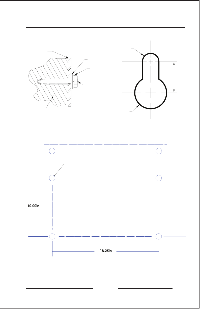
GRAPHICS
ENCLOSURE
MOUNTING
FLANGE
FLAT WASHER
LOCKWASHER
0.25in / 6.4mm
DIA BOLT
1 Receiving & Mounting
0.312in
[8.00mm]
DIA
0.750in
[19.00mm]
WALL
0.750in
[19.00mm]
DIA
RECOMMENDED MOUNTING KEYHOLE SLOT USED ON
HARDWARE LOADING STYLE-5054 MOUNTING FLANGE
USE 0.25in / 6.4mm DIA
BOLTS - FOUR (4) PLACES
254mm
464mm
ATevo STYLE-5054 ENCLOSURE
WALL-MOUNTING PATTERN
ATevo
5
Page 22

1 Receiving & Mounting
1.7.2 Floor-Mounting
To install ATevo onto a horizontal surface, the standard enclosure
does not need to be modified, but a special floor mounting accessory
is required. The kit includes a set of mounting brackets that elevate
the top of ATevo approximately 47in /1194mm above floor level,
with provisions for floor anchoring. The kit also includes appropriate
hardware and installation instructions for the floor-mounting
procedure.
When floor-mounting ATevo, consider the following:
1. Locate anchor bolt holes at least 4.25in /108mm from any wall,
to allow clearance behind the mounting brackets.
2. Select conduit entrances with planned ac input and dc output
wiring in mind. By using pre-fab knockouts on enclosure sides
or bottom, the cabinet shroud can be removed for internal
servicing without removing ATevo from the floor stand.
3. Location requirements:
» Free of drips and splatter. If falling particles and liquids are
a problem, install a NEMA Type 2 drip shield accessory.
» Between 0 and 122 °F / -18 and 50 °C, with relative humidity
between 0% and 95% non-condensing.
» Must be free of flammable or explosive materials.
4. Maintain at least 6in /152mm of free air on all vented surfaces
for cooling.
5. Allow 36in /914mm front clearance for operation and
maintenance.
PROCEDURE
Install four (4) 0.25in / 6.4mm anchor bolts (not supplied) rated
to support the unit weight plus a minimum safety factor of two (2)
times, into floor.
Assemble the floor-mounting accessory on to the anchor bolts as
shown. Place ATevo onto vertical posts, add appropriate mounting
hardware, and tighten.
Refer to the following graphics for floor mounting patterns and
enclosure footprints.
6
ATevo
Page 23

GRAPHICS
19.75in
502mm
1 Receiving & Mounting
47.75in
1213mm
0.437in / 11mm
FLOOR MTG HOLE
FOUR (4) PLACES
10.00in
ATevo STYLE-5054 ENCLOSURE
FLOOR-MOUNTNG PATTERN
WALL
4.25in
min.
108mm
18.25in
463mm
0.375in / 9.5mm
FLOOR-MOUNTING
HARDWARE
FOUR (4) PLACES
ATevo
10.00in
254mm
7
Page 24

1 Receiving & Mounting
1.7.3 Rack-Mounting
ATevo can be installed into most 23in/584mm and 24in/610mm relay
racks with standard EIA hole spacing. ATevo’s enclosure does not
need to be modified for rack mounting, but a special kit is required.
The kit includes two (2) mounting brackets, appropriate hardware,
and Installation Instructions for the rack-mounting procedure.
When rack-mounting ATevo, consider the following:
1. Rack must be strong enough to properly support the unit’s
weight. Refer to Weight Table in Section 1.6.1.
2. Select conduit entrances such that planned ac input and dc
output conduit is accessible after rack-mounting. Note the
standard pre-fab conduit knockouts located on the sides, top,
and bottom of the enclosures.
3. Location requirements:
» Free of drips and splatter. If falling particles and liquids are
a problem, install a NEMA Type 2 drip shield accessory.
» Between 0 and 122 °F / -18 and 50 °C, with relative humidity
between 0% and 95% non-condensing.
» Must be free of flammable or explosive materials.
4. Maintain at least 6in /152mm of free air on all vented surfaces
for cooling.
5. Allow at least 36in /914mm front clearance for operation and
maintenance.
PROCEDURE
To rack mount ATevo, first install mounting brackets into rack using
proper hardware (not supplied). Second, mount ATevo onto installed
brackets, using supplied kit hardware. Provide at least 6in /152mm
of free air above and below ATevo for cooling. Refer to the following
graphics for rack-mounting configurations.
8
ATevo
Page 25
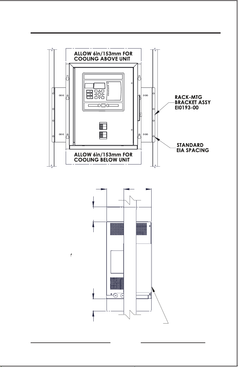
GRAPHICS
6in/153mm
COOLING
6in/153mm
COOLING
8.50in
216mm
4.00in
57mm
R
A
C
K
1 Receiving & Mounting
ATevo STYLE-5054 RACK-MOUNTING
4.00in
57mm
8.50in
216mm
6in/153mm
COOLING
6in/153mm
COOLING
R
A
C
K
ATevo
0.25in/6.4mm
MTG. BOLTS
9
Page 26

2 Wiring
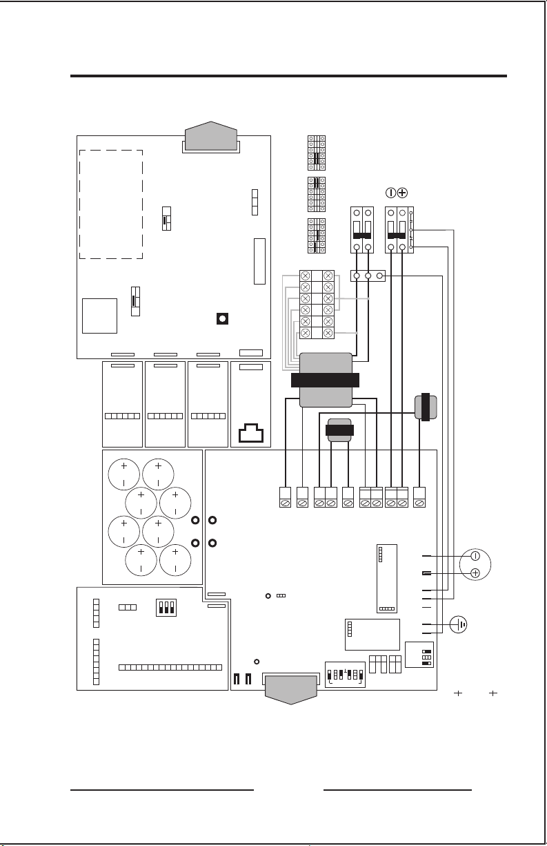
2.1 Mechanical Diagram and Component Location
ATevo has the following mechanical layout and wiring diagram
screen-printed onto its patented, internal acrylic safety shield.
ATevo is composed of these components and subsections:
• A1 - Main Control PC Board
• A2 - Power Board
• A4 - Auxiliary I/O Board - optional
• A7 - Filter Capacitor (C1x) Board
• A9 - AC Surge Suppressor MOV Board
• A10 - Remote Temperature Probe - optional
• A12 - Serial Communications Adapter(s) - optional
• A13 - Forced Load Sharing Communications Adapter - optional
• A22 - Ethernet Communications Adapter - optional
• C2 - Eliminator Filter Capacitor - optional
• CB1 - AC Input Circuit Breaker (and input terminals L1/L2)
• CB2 - DC Output Circuit Breaker (and output terminals +/-)
• L1 - Main Filter Inductor
• L2 - Secondary Filter Inductor
• T1 - Power Isolation Transformer
10
ATevo
Page 27
PUSH CARD IN
TO EJECT
SD MEMORY
CARD
PORT 1
RXD/RA (-)
P1
TXD/TA (-)
JP4
RE-FLASH
A12 Serial
Adapter
GND
RTS/TB (+)
CTS/RB (+)
ATevo Silkscreen (1PH 6-25 Adc)
RIBBON CABLE TO
PRGM
NORM
ENABLE
PORT 2
P10
(EN5034-##)
SHIELD
RXD/RA (-)
P1
A12 Serial
TXD/TA (-)
CTS/RB (+)
A2 POWER BOARD
HIGH LEVEL
DETECT SHUTDOWN
DIS
EN
J1
A1 Main Control Board
PORT 3
P11
P1
(EN5034-##)
Adapter
GND
SHIELD
TXD/TA (-)
RXD/RA (-)
RTS/TB (+)
(EN5031-##)
PUSH TO
RESET
P12
(EN5034-##)
A12/13 Serial
Adapter
GND
SHIELD
RTS/TB (+)
CTS/RB (+)
P1
SW13
ETHERNET
P1
ALARM
1 2 3
C NC NO
TB6 COMMON
P2
P13
(EN5035-##)
A22 Ethernet
Adapter
J1
AC INPUT VOLTAGE SELECTION
(OPTION NOT AVAILABLE ON SINGLE INPUT UNITS)
USE BOTH JUMPERS WHEN MAKING SELECTIONS
H1 H3 H2 H5 H4 H2 H1 H3 H2 H5 H4 H2 H1 H3 H2 H5 H4 H2
H2
MAIN CONTROL CARD VIEWED FROM BACK OF DOOR
H4
H2 H5
H3
H1
T1 Transformer
120 Vac INPUT 208 Vac INPUT 240 Vac INPUT
L1 Inductor
AC INPUT
L1 / Line
L2 / Neutral
INPUT BREAKER CB1
Negative
Positive
DC OUTPUT
OUTPUT BREAKER CB2
AUX-CB2
(EN5039-##)
A9 MOV BOARD
CONTACTS
STRIP WIRE INSULATION 1/2in
USE COPPER CONDUCTOR ONLY
L2 Inductor
2 Wiring
TORQUE SCREWS TO 31 in-lb
DANGER
ATevo Series
Component Layout (6-25 Adc)
A7 Filter
Board
1 NA
2 NA
3 NA
4 NA
MOC
TB1 TB3
)+( 1B
)-( 1B
)+( 2B
)-( 2B
)+( 3B
)-( 3B
)+( 4B
)-( 4B
S1
(EN5040-##)
A4 Aux I/O Board
TB4 TB2
1YALER
NC
NC
NO
COM
4YALER
3YALER
2YALER
NC
NC
NO
NO
NO
COM
COM
HIGH VOLTAGE
COM
(EN5038-##)
NEG
POS
NC
NO
X4
X1
L2-1
L1-2
DANGER
TBS1 TBS2
HIGH VOLTAGE
J105
P1
6YALER
5YALER
NC
NO
COM
COM
TP4 Output (+)
TP3 Output (-)
TP2 (+)
TP1 (-)
P1
RIBBON CABLE TO
A1 MAIN CONTROL
JP101
(EN5037-##)
A2 Power Board
JP103 LOCAL
REMOTE SENSE
ATevo
L1-1
J104
JP104
Y2
Y1
J102
POS 1
REMOTE SENSE
TB1
CB2 POS
CB2 NEG
C2 (-)
EN5042-XX
C2 (+)
COMM
A24 DC POWER
SUPPLY
J101
EARTH
AC MOV
GROUND DETECT
ENABLED
DISABLED
SIG 1
NEG 3
GND 2
BATT TEMP
TB8
L2-2
C2 Eliminator
Capacitor
CB2
CB1
GROUND
JP102
TP4
OUTPUT
POS
TP3
OUTPUT
NEG
11
Page 28

2 Wiring
2.1.1 Main Control Board (A1)
Shown on top-right of silkscreen. Mounted on the ATevo front panel
door. Contains display, buttons, alarm indicators, and is responsible
for battery charger controls.
2.1.2 Power Board (A2)
Shown on bottom-left of silkscreen. Mounted on heat sink along
left side of ATevo. Contains most power electronic connections,
and terminal blocks for remote sense and battery temperature
compensation options.
2.1.3 Auxiliary I/O Board (A4) - optional
Shown at top-left of silkscreen. Bolted to heat sink on the left side,
above the Power Board. Plugs directly into Power Board (A2).
• six (6) relays, four (4) Binary Inputs, and four (4) Analog Inputs
• relays can be configured to indicate status of six (6) different alarms
or status points
• independently-isolated Binary Inputs can be configured to report ON/
OFF status of four (4) controls
• Analog Inputs include input scaling and can report the status of four
(4) analog controls referenced to the dc bus
2.1.4 Filter Capacitor Board (A7)
Shown near top-left of silkscreen. Bolted to top of the Power Board
(A2). The capacitors (C1x) filter ‘ripple’ from the dc output.
2.1.5 AC Surge Suppressor MOV Board (A9)
Shown to left of AC Circuit Breaker (CB1) on silkscreen. Mounted to
top-left side of breaker bracket. Contains ac input surge suppression
and filtering. It is located for easy access, examination, and
replacement in case an input transient event should occur.
2.1.6 Serial Communications Adapter (A12) - optional
Shown above Ethernet Comm. Adapter (A22) on silkscreen. Up
to three (3) Serial Communications Adapter boards (A12) can be
plugged into the Main Control Board (A1) at locations P10, P11, and
P12. This option supports DNP3 and Modbus protocols, and can be
configured to support 2-wire or 4-wire RS-232 connections, or 2-wire
or 4-wire RS-485 connections.
12
ATevo
Page 29

2 Wiring
2.1.7 Forced Load Sharing Comm Adapter (A13) - optional
Mounted similarly to Serial Communications Adapter (A12).
2.1.8 Ethernet Communications Adapter (A22) - optional
Shown directly to bottom-left of Main Control Board (A1) on
silkscreen. Plugs into Main Board at P13. Supports DNP3 and
Modbus protocols via 10/100 copper Ethernet connection.
2.1.9 Eliminator Filter Capacitor (C2) - optional
Shown below Power Board on silkscreen. Mounted on bottom-left
under Power Board. Provides the additional ripple filtering, required
for the ‘filtered eliminator’ option.
2.1.10 AC Input Circuit Breaker (CB1)
Located in center of ATevo, about one third from bottom. Protects
ATevo ac wiring, and can be used to disconnect from ac source.
2.1.11 DC Output Circuit Breaker (CB2)
Located at bottom-center of ATevo. Protects ATevo dc wiring, and can
be used to disconnect ATevo from battery and system dc load(s).
2.1.12 Main Filter Inductor (L1)
Shown in center of silkscreen. Located on bottom-left of back wall. It
is part of the dc filter, lowering ripple.
2.1.13 Secondary Filter Inductor (L2)
Shown bottom-center of silkscreen. Located on bottom of back wall
to right of Filter Inductor (L1). It is also part of the dc filter.
2.1.14 Power Isolation Transformer (T1)
Shown at center of silkscreen. Located on back wall above the filter
inductors (L1/L2). Provides isolation and converts ac input voltage to
appropriate potential, prior to rectification.
NOTICE ATevos with the multi-tap ac input option (smart part
code ‘MT1/2’), feature a terminal block (TB-H#) mounted above
the AC Input Circuit Breaker (CB1) for voltage selection. Jumper
positions are shown on silkscreen to right of Power Isolation
Transformer (T1). See Section 2.3.
ATevo
13
Page 30

2 Wiring
2.2 Removing Protective Safety Shield
! WARNING To prevent injuries, the ATevo safety shield
must always be installed when charger is in operation and/or
energized.
STEPS
• A standard flat blade screwdriver is required.
• Open the ATevo front panel door to access safety shield.
• Remove the two (2) screws that attach the safety shield to the
ATevo, one above AC Input Breaker (CB1), the other below the
DC Output Breaker (CB2).
• Grab the safety shield on both left and right sides, and gently lift
up and off of AC Input and DC Output Circuit Breakers.
• Reverse procedure for reinstalling the safety shield.
2.3 ATevo with Selectable Input Voltage - optional
ATevo may be equipped with a multi-tap ac input voltage, in two (2)
options for field configuration:
• 120, 208 or 240 Vac 60Hz - ‘MT1’ in smart part number
• 115, 220, or 240 Vac 50/60Hz - ‘MT2’ in smart part number
2.3.1 Determining if Multi-Tap Option is Present
Check the ATevo nameplate. If the ac input voltage is listed as
120/208/240 or 115/220/240 Vac, the ATevo is equipped with the
multi-tap option. If the nameplate is not visible:
• Open the ATevo front panel door.
• Behind the safety shield, look for a gray terminal block directly
above the AC Input Circuit Breaker (CB1).
» Reference the input voltage selection silk-screened on the
center-right of the safety shield.
» If this terminal block is present, the ATevo is equipped with
the multi-tap ac input voltage option.
14
ATevo
Page 31

2.3.2 Verifying Multi-Tap AC Input Voltage Setting
Before you connect ac power to ATevo, inspect
the present ac input voltage setting, and
confirm the correct jumper positions for the
desired ac input supply voltage. The multi-tap
ac input voltage setting can be verified without
removing the safety shield.
• Open ATevo’s front door and locate
the Multi-Tap terminal block above
the AC Input Breaker (CB1).
• Observe the relative locations of the
RED jumpers in the Multi-Tap terminal
block (TB-H#).
• Refer to the adjacent diagram to
confirm the present ac input voltage
setting is correct.
2.3.3 Modifying Multi-Tap AC Input Voltage Setting
! WARNING Before changing the voltage selection
jumper, shut down ATevo and lock out ac and dc power supplies.
Turning off (opening) the ATevo internal circuit breakers does not
eliminate live voltages inside the enclosure.
• Standard flat blade screwdriver is required.
• Remove the ATevo safety shield per Section 2.2.
• Locate the multi-tap terminal block.
• Set locations of RED jumpers for desired ac input voltage, per
Section 2.3.2.
» Carefully pry out jumpers in existing locations.
» Re-install jumpers into new (correct) locations.
• Re-check jumper locations and confirm jumpers are properly
seated.
2 Wiring
ATevo
15
Page 32

2 Wiring
2.4 Making AC Input Connections
ATevo is a commercial product. It is not intended for use at
any time in a residential environment or to be powered by lowvoltage public mains.
It is the responsibility of the installer to provide ac supply wiring
approved for use in the country where installed. When selecting
wire sizes, consult the data nameplate decal affixed to ATevo for
voltage and current requirements.
Follow these steps to supply proper ac power to ATevo:
1. Confirm that the ATevo nameplate voltage rating is correct for
the ac input supply voltage. If ATevo has the Multi-Tap ac input
voltage option, make sure the setting matches the ac input
supply voltage per Section 2.3.2.
2. Use a branch circuit breaker or fused disconnect switch
upstream from ATevo. This device should have lockout
capabilities so that the ac input supply to ATevo can be deenergized for unit maintenance. A time-delay circuit breaker or
slow-blow fuse is recommended.
3. Size the branch circuit breaker or fused disconnect switch
for ATevo’s maximum ac input current as listed on the data
nameplate decal.
4. Size the ac input wiring per the National Electric Code (NEC),
Canadian Electrical Code, local and site codes for the trip rating
of the branch circuit breaker or fused disconnect switch.
5. Do not run external ac input power wiring through the same
conduit as external dc wiring.
6. All site requirements of the facility take precedence over these
instructions.
16
ATevo
Page 33

2 Wiring
NOTES
• Conduit must be properly grounded, and in compliance with the
national wiring rules of the country where installed.
• Use copper or aluminum conductors only.
• For 120 Vac, connect the neutral leg to input terminal (CB1-L2).
PROCEDURE
1. Remove safety shield per Section 2.2.
2. Run ac input supply wiring into ATevo, ending at the AC Input
Circuit Breaker (CB1) and ground stud.
3. Connect wires to appropriate locations on AC Input Circuit
Breaker (CB1-L1/L2) and system ground stud, as indicated on
drawing.
4. Using a flat-blade screwdriver, securely tighten the compression
screws on AC Breaker (CB1-L1/L2).
5. Securely tighten ground wire on system ground stud.
6. Check all connections and reinstall safety shield.
ATevo
17
Page 34

2 Wiring
2.5 Making DC Output Connections
Installer is responsible to provide suitable dc output, battery, and dc
load wiring.
Follow these steps to connect the battery to ATevo:
1. Size the dc wiring to minimize voltage drop. Acceptable wire
size depends on the installation. As a guideline, voltage
drop should not exceed 1% of nominal output voltage at
full current. Refer to the following table to determine the
voltage drops for various wire sizes, currents and distances.
Wire Sizing Chart
Voltage Drop per 100ft / 30.5m of Wire
(for copper at 68 °F / 20 °C)
Wire
Size
(AWG)
#16
#14
#12
#10
#8
#6
#4
EXAMPLE: 100ft / 30.5m of #8 AWG wire at 16A has a 1.1V drop.
6 12 16 20 25
2.5V 5.0V 6.7V 8.2V 10.5V
1.6V 3.2V 4.2V 5.3V 6.6V
1.0V 2.0V 2.6V 3.3V 4.2V
0.63V 1.3V 1.7V 2.1V 2.6V
0.40V 0.80V 1.1 V 1.3V 1.7V
0.25V 0.50V 0.66V 0.83V 1.1 V
0.16V 0.32V 0.42V 0.52V 0.65V
DC Current (Amperes)
2. ATevo is factory wired to regulate output voltage at the
output terminals. If total voltage drop is greater than 1%
(e.g. 1.3V for a 130 Vdc system), remote sense wiring is
recommended (see Section 11).
3. Do not run external ac and dc power wiring through the
same conduit.
4. Facility-specific installation requirements take precedence.
18
ATevo
Page 35

2 Wiring
PROCEDURE
1. Use a dc disconnect switch or circuit breaker between ATevo and
the dc bus. This device should have lockout capability to allow
ATevo to be disconnected from the dc bus for maintenance.
2. Remove safety shield (see Section 2.2).
3. Run dc wiring to Output Circuit Breaker (CB2).
4. Connect wires to appropriate locations on the DC Output
Breaker (CB2+/-) as indicated on drawing above.
5. Using a flat-blade screwdriver, securely tighten compression
screws on DC Output Breaker Terminals (CB2+/-).
6. Reinstall safety shield after you have made and checked all
connections.
ATevo
19
Page 36

2 Wiring
2.6 Remote Voltage Sense
You can wire ATevo to regulate output voltage at the battery
terminals instead of at the battery charger dc output terminals
(CB2+/-). See Section 11 for information and wiring instructions.
2.7 Wiring ATevo Common Alarm
ATevo Main Control Board (A1) is equipped with a ‘summary’
Common Alarm relay. This relay contact transfers when any one (1)
or more of the standard ATevo alarm(s) become active. One (1) set
of form-C alarm contacts is provided, and are accessible via terminal
block (A1-TB6) on the Main Control Board. Refer to figure below.
20
ATevo
Page 37

PROCEDURE
1. Allow 30in / 762mm of wire inside enclosure, and trim
excess.
2. Route annunciator wires to ATevo front panel door by
following existing harness past door hinge.
3. Use two (2) wire ties and allow a 4-6in / 102-153mm
loop for the hinge.
4. Trim wires to length to connect to alarm terminal block
(A1-TB6), and strip 0.25in / 6.4mm of insulation.
5. Make connections at A1-TB6 and tighten compression
screws.
NOTES
1. Alarm contacts are rated at 0.5A / 125 Vac or Vdc.
2. Common Alarm relay terminal block (A1-TB6) is
compression type, accepting wire sizes #22-14 AWG.
3. Terminals are labeled in non-alarm condition.
4. If user alarm contacts (A1-TB6) are to drive inductive dc
loads (e.g. a larger dc relay) an external protective diode
must be installed at the dc relay to avoid equipment
damage. Refer to Application Note (JD5011-00).
2 Wiring
2.8 Wiring Relays on Auxiliary I/O Board
When provided, the optional Auxiliary Alarm I/O Board (A4) is
mounted to the heat sink, above the Power Board (A2) on the
left side of the ATevo. See Section 12 for more information and
wiring instructions.
2.9 Wiring Temperature Compensation Probe
The battery temperature compensation, or ‘TempCo’, probe
(A10) contains a temperature-dependent resistor in an epoxy
module. When used, this probe is installed on the battery. See
Section 11 for more information and wiring instructions.
ATevo
21
Page 38

2 Wiring
2.10 Wiring Serial Communications Adapters
ATevo will support up to three (3) optional Serial Communications
Adapter pc boards. They mount on the ATevo’s front panel door,
by pluging directly into the Main Control Board (A1) via connection
points P10, P11, and P12. Refer to the supplementary ATevo
Communications Manual (JA0102-54) for more information and
wiring instructions.
2.11 Wiring Ethernet Adapter Board
ATevo will support an optional Ethernet Adapter Board (A22). It
mounts on the ATevo’s front panel door, by pluging directly into
the Main Control Board (A1) via connection point P13. Refer to the
supplementary ATevo Communications Manual (JA0102-54) for
more information and wiring instructions.
22
ATevo
Page 39

MODES &
METHODS
MAIN
DISPLAY
NAVIGATION
& CONTROLS
HINDLE
HEALTH
ALARM
SECTION
AC INPUT &
DC OUTPUT
BREAKERS
3 Controls & Navigation
3.1 Front Panel Controls and Indicators
ATevo front panel controls and indicators are organized into six (6)
major groups or sections.
ATevo
23
Page 40

3 Controls & Navigation
3.1.1 ATevo Main Display
A back-lit Liquid Crystal Display (LCD) shows all charger status and
configuration information. The display is discussed in Section 3.2.
3.1.2 Navigation and Control Button Group
This group of buttons (MENU, ESC, EDIT/ENTER, LEFT, RIGHT, UP, and
DOWN) is used to navigate through ATevo display screens, and user
interface menus. Use of these controls is discussed in Section 3.3,
Main Menu and Navigation.
3.1.3 Operation Modes and Methods Button Group
This group of buttons (DISPLAY MODE, CHARGE MODE, and
EQUALIZE METHOD) is used to select the mode of operation. Use of
these controls is discussed in Section 5.1.
3.1.4 Alarm Section
The alarm section consists of the discrete alarm indication LEDs, the
AC ON indicator (LED), and the ALARMS button. An alarm indicator
will light when its associated alarm is activated. The AC ON
indicator is lit when ac power is detected by the Main Control Board
(A1). The ALARMS button is used to enter screens which display
alarm statuses. Alarms and indicators are discussed in Section 7.
3.1.5 Hindle Health System (HHS) Section
The Hindle Health System section consists of the HEALTH BUTTON
(HH) and the RED and GREEN health indication LEDs at the bottom
of the panel. The Hindle Health System is discussed in Section 8.
3.1.6 AC Input and DC Output Breakers
The AC Input Circuit Breaker (CB1) is directly below the front control
panel. When opened, the Input Breaker disconnects all internal
ATevo connections from the ac source except for the breaker terminal
(CB1-L1/L2), where the ac input feed is connected.
The DC Output Circuit Breaker (CB2) is below the AC Breaker. When
opened, the DC Breaker disconnects ATevo output from the dc bus.
! WARNING There still may be live dc power connected to some
of ATevo’s internal boards (this will include any relays wetted by the
battery voltage).
24
ATevo
Page 41

3 Controls & Navigation
3.2 Display
The ATevo front panel features a back-lit Liquid Crystal Display (LCD)
that is capable of displaying various fonts, text sizes, and graphical
objects. The graphical display, in combination with the front panel
control buttons, provides an easy-to-use, powerful interface. The
various ATevo screens include user prompts and navigation icons to
provide an intuitive and hedonic experience.
ATevo screens can be grouped, by function, into four (4) basic types:
• HOME Screen
• Configuration Screens
• Status Screens
• Hindle Health Screens (HHS)
3.2.1 Home Screen
The HOME screen is the primary ATevo display, and is active most
of the time ATevo is energized. Other screens are displayed during
configuration changes, during testing, when the user requests more
detailed status than what is provided on the HOME screen, or when
the user wishes to utilize one of the advanced ATevo features.
• The Factory Default HOME Screen displays the output voltage
(Vdc) and output current (Adc) in a large font for easy reading.
• ‘Float’ or ‘Equalize’ will appear on the left side of the top of the
display to indicate that the charger is actively in either FLOAT or
EQUALIZE CHARGE MODE.
ATevo
25
Page 42

3 Controls & Navigation
• ‘Eqlz Mthd: Man’ or ‘Eqlz Mthd: Auto’ will appear on the right
side of the top of the display to indicate that the EQUALIZE
METHOD is presently configured for MANUAL TIMER or
AUTOMATIC TIMER mode.
• If a Temperature Compensation (TempCo) Probe option is
installed and enabled, the present battery temperature and
normalized voltage set point will also appear on the display (see
Section 10 for more details on the TempCo option and display).
3.2.2 Conguration Screens
These screens are used for changing ATevo set points and
configuration. Many of these screens will be described in Startup
and Configuration, Section 4. Other configuration screens for
installed options will be described later in their respective installed
option sections.
3.2.3 Status Screens
ATevo Status screens do not permit any system changes, and are
used only for viewing information. Most of the status screens (e.g.
Event Log and Active Alarm List) are covered in Advanced Operation,
Section 6. The HOME screen can be thought of as a ‘special’ Status
Screen in that it can indicate dc output voltage (Vdc), dc output
current (Adc), and status of Equalize/Float mode and method.
3.2.4 Hindle Health System Screens
Hindle Health System screens are associated with the Hindle Health
button (HH). When (HH) is pressed, ATevo enters a user-assisted selfdiagnostic mode. Screens prompt the user to participate in a series
of tests that confirm that ATevo is operating correctly. For more
information on the Hindle Health System, see Section 8.
26
ATevo
Page 43

3 Controls & Navigation
3.3 Main Menu and Navigation
The navigation control buttons (MENU, ESC, EDIT/ENTER, LEFT,
RIGHT, UP and DOWN) are used to navigate through ATevo screens
and menus. This system is intuitive to most people as it is similar to
universally-adopted televison remote control navigation buttons.
3.3.1 MENU and ARROW Buttons
Press the MENU button to access the Main Menu. The first six (6)
menu selection icons appear. Use the UP, DOWN, LEFT, or RIGHT
arrow buttons to navigate. Icons appear in inverse video when
selected. In the screenshot below, the user has already pressed the
DOWN arrow to select ‘Event Logs’.
The top-left of the screen indicates the Main Menu is displayed. The
top-right displays an up and/or down arrow icon that indicates that
more menu selection icons are available if you continue to navigate
in the direction of the arrow(s). In the screenshot above, both up and
down arrow icons appear in the top right corner. This indicates that
menu icons can be accessed by navigating either up or down from
the presently selected icon.
ATevo
27
Page 44

3 Controls & Navigation
3.3.2 EDIT/ENTER Button
Pressing the EDIT/ENTER button will activate the feature or function
selected onscreen. As an example, in the prior screenshot, ‘Event
Logs’ was selected. Pressing EDIT/ENTER with this selection causes
the following screen to open.
Pressing EDIT/ENTER with ‘View event log’ selected, as shown above,
takes the user to an event log entry as seen below.
The screenshot above is an example where a left and right arrow icon
appear in the top right of the display. This indicates that pressing
either LEFT or RIGHT arrow buttons will show additional screens.
LEFT and RIGHT arrow buttons are also used when moving between
numbers when setting parameters or between characters when
setting passwords.
28
ATevo
Page 45

3 Controls & Navigation
3.3.3 Navigation Conventions in this Manual
In the previous two (2) pages, a sequence of commands executed
a sequence of screens to display. That example was provided to
illustrate the use of the UP, DOWN, LEFT, RIGHT arrow buttons, and
the EDIT/ENTER button for navigation.
The full command sequence shown was:
1. Press MENU to open the Main Menu screen.
2. Press DOWN to select EVENT LOGS.
3. Press EDIT/ENTER to open ‘Event Logs’ screen.
4. Press UP OR DOWN arrows to navigate to ‘View event log’.
5. Press EDIT/ENTER to open an event log screen.
Using a full command sequence with every command in this manual
would lead to needless repetition and tedious document length. As
the above example illustrates, most of the repetition comes from
listing every navigation button push.
ATevo uses a simple, nearly universal navigation system that is used
by most tv remote controls. It is not necessary to list the following
navigation button pushes: UP, DOWN, RIGHT, LEFT or EDIT/ENTER.
This convention results in a streamlined sequence of ATevo-specific
commands.
For our example, this is:
1. Press MENU to open the Main Menu screen.
2. Execute the EVENT LOGS command on the Main Menu.
3. Execute the ‘View event log’ command on the Events Logs screen.
ATevo
29
Page 46

3 Controls & Navigation
To simplify further, we use a shorthand convention that makes use of
the ‘>’ character between commands.
Navigation Convention: Command > Command > Command
With this convention, the previous example’s command sequence is:
MENU > EVENT LOGS > ‘View event log’.
Screen Convention:
In the same way that the character ‘>’ is used between commands
in a sequence, the same character appears between a sequence of
screens.
3.3.4 Escape (ESC) Button
In general, pressing ESC returns back one menu level. The examples
below illustrate its use:
• If Main Menu displayed: ESC will return to HOME screen.
• If in SYSTEM SETTINGS screen, pressing ESC will return to Main
Menu. Pressing ESC again will return to the HOME screen.
30
ATevo
Page 47

4 Startup & Conguration
4.1 Startup
4.1.1 Understanding the Startup Sequence
ATevo is pre-configured to work with most common batteries and
loads without further adjustment.
When you start ATevo for the first time, the battery charger will:
• Use the FACTORY SETTINGS (float voltage, equalize voltage, etc)
listed in the following tables. These settings may be changed
after startup if necessary.
• Take about fifteen (15) seconds to start. Control circuitry will
‘soft start’ ATevo, such that dc output voltage and dc current
increase gradually to rated values.
4.1.2 Factory Settings Tables
Factory settings for each ATevo are summarized in the tables on the
following four (4) pages.
ATevo
31
Page 48

4 Startup & Conguration
32
24 Vdc ATevo Set Points & Defaults
Parameter Low Range Set Point High Range Set Point Nominal (Default) Units
Float Voltage 22�0 29�5 26�0 Volts
Current Limit (50% rating) (110% rating) (110% rating) Amperes
Equalize Voltage 23�4 32�0 28�0 Volts
Equalize Time 0�1 99�0 24�0 hours
High DCV Alarm 24�0 38�0 28�8 Volts
ATevo
Low DCV Alarm 14�0 25�0 24�0 Volts
HDCV Shutdown 24�0 38�0 28�8 Volts
High Level Detect 24�0 38�0 28�8 Volts
Low Level Detect 15�0 24�0 21�0 Volts
AC Ripple Alarm 20 250 20 milli-Volts
End of Discharge 15�0 24�0 21�0 Volts
Ground Fault NEG(-) 10 40 15 kilo-Ohms
Ground Fault POS(+) 10 40 15 kilo-Ohms
Page 49

4 Startup & Conguration
48 Vdc ATevo Set Points & Defaults
Parameter Low Range Set Point High Range Set Point Nominal (Default) Units
Float Voltage 44�0 58�0 52�0 Volts
Current Limit (50% rating) (110% rating) (110% rating) Amperes
Equalize Voltage 46�0 61�0 56�0 Volts
Equalize Time 0�1 99�0 24�0 hours
High DCV Alarm 48�0 76�0 57�6 Volts
ATevo
Low DCV Alarm 28�0 50�0 48�0 Volts
HDCV Shutdown 48�0 76�0 57�6 Volts
High Level Detect 48�0 76�0 57�6 Volts
Low Level Detect 33�0 48�0 42�0 Volts
AC Ripple Alarm 20 250 20 milli-Volts
End of Discharge 33�0 48�0 42�0 Volts
Ground Fault POS(+) 10 40 15 kilo-Ohms
Ground Fault NEG(-) 10 40 15 kilo-Ohms
33
Page 50

4 Startup & Conguration
34
130 Vdc ATevo Set Points & Defaults
Parameter Low Range Set Point High Range Set Point Nominal (Default) Units
Float Voltage 110�0 140�0 131�0 Volts
Current Limit (50% rating) (110% rating) (110% rating) Amperes
Equalize Voltage 117�0 149�0 139�0 Volts
Equalize Time 0�1 99�0 24�0 hours
High DCV Alarm 120�0 175�0 144�0 Volts
ATevo
Low DCV Alarm 70�0 141�0 120�0 Volts
HDCV Shutdown 120�0 175�0 144�0 Volts
High Level Detect 120�0 175�0 144�0 Volts
Low Level Detect 87�0 120�0 105�0 Volts
AC Ripple Alarm 20 250 70 milli-Volts
End of Discharge 87�0 120�0 105�0 Volts
Ground Fault POS(+) 10 40 15 kilo-Ohms
Ground Fault NEG(-) 10 40 15 kilo-Ohms
Page 51

4 Startup & Conguration
260 Vdc ATevo Set Points & Defaults
Parameter Low Range Set Point High Range Set Point Nominal (Default) Units
Float Voltage 220�0 282�0 262�0 Volts
Current Limit (50% rating) (110% rating) (110% rating) Amperes
Equalize Voltage 234�0 298�0 278�0 Volts
Equalize Time 0�1 99�0 24�0 hours
High DCV Alarm 240�0 288�0 350�0 Volts
Low DCV Alarm 140�0 282�0 240�0 Volts
ATevo
HVDCV Shutdown 240�0 288�0 350�0 Volts
High Level Detect 240�0 288�0 350�0 Volts
Low Level Detect 177�0 244�0 210�0 Volts
AC Ripple Alarm 20 250 70 milli-Volts
End of Discharge 177�0 244�0 210�0 Volts
Ground Fault POS(+) 10 40 15 kilo-Ohms
Ground Fault NEG(-) 10 40 15 kilo-Ohms
35
Page 52

4 Startup & Conguration
4.1.3 Checking Installation
Prior to powering up ATevo for the first time, it is recommended that:
• You have followed installation instructions carefully.
• You check that ac input supply voltage and battery voltage
match information on ATevo nameplate.
• If ATevo features the Multi-Tap option, verify the ac input jumpers
on INPUT VOLTAGE SELECTION terminal block are correct for the
ac supply voltage (see Section 2.3.2).
• Open the front panel, and check battery polarity at the DC
Output Circuit Breaker (CB2+/-).
4.1.4 Starting Up
After confirming that all connections to ATevo are properly made,
start up as follows:
• Turn ON (close) AC Input Circuit Breaker (CB1) first. You should
hear a soft hum from ATevo as output increases.
• Main ATevo Display should start up and indicate dc output
voltage. If the display does not light, do not proceed. Turn OFF
(open) the AC Breaker (CB1) and recheck connections.
NOTICE If you attempt to turn ON the DC Output Circuit Breaker
(CB2) first, it may trip due to the filter capacitor in-rush.
• Turn ON (close) the DC Output Circuit Breaker (CB2).
• If any error codes or alarms appear on the Main ATevo Display
and/or Alarm Indicator LEDs, see Section 7.
• Interpret the origin and resolution of the indication before
proceeding.
4.1.5 Home Screen
The default HOME screen appears after power up showing the
dc bus voltage and dc charger current, along with the status for
CHARGER MODE and EQUALIZE METHOD on the top line. CHARGE
MODES and EQUALIZE METHODs are described in Section 5.1.
ATevo will automatically switch back to the HOME screen if no
buttons are pushed for ten (10) minutes, or by pressing ESC one
or more times. Each press of ESC returns one level until HOME is
reached.
36
ATevo
Page 53

4 Startup & Conguration
CHARGER MODE
‘Float’ = FLOAT
MODE
‘Equalize’ =
EQUALIZE MODE
EQUALIZE METHOD
‘Man’ = MANUAL
TIMER
‘Auto’ =
AUTOMATIC TIMER
4.2 Conguring Basic Set Points and Alarms
The ATevo is the second generation of AT Series microprocessorcontrolled float battery chargers. Because its configuration button
sequence is identical, users of legacy AT10.1 chargers will easily
adapt to the ATevo. This section details how to configure basic ATevo
set points, and alarms found also on legacy AT10.1 chargers:
• Float Voltage
• Equalize Voltage
• Equalize Timer
• High DC Voltage Alarm
• Low DC Voltage Alarm
• Current Limit Level
4.2.1 How to Congure General Parameter Settings
You can adjust ATevo settings during operation using the front panel
controls. When you first press EDIT/ENTER, ATevo prompts you to set
the first parameter in the list (Float Voltage).
To set parameters, do the following:
• Press UP or DOWN (or hold down to scroll) until desired value
displays. Each parameter has a minimum and maximum limit as
listed in the tables in Section 4.1.2.
• Press EDIT/ENTER to save setting. ATevo prompts you to set the
second parameter.
• Continue in the same manner to set all six (6) parameters in the list.
If you want to skip setting any parameter, press EDIT/ENTER (or
RIGHT arrow) to bypass it.
• When finished setting the sixth parameter (Current Limit), press EDIT/
ENTER to save setting and return to normal operation.
• Any changes that you have made take effect immediately. ATevo uses
its last saved values if it is powered down and returned to service.
ATevo
37
Page 54

4 Startup & Conguration
NOTICE The Basic ATevo Set Point mode can also be entered from
the Main Menu by selecting the BASIC SETTINGS icon.
While adjusting settings, if the user does not press a front panel key
for ten (10) minutes, Edit Mode ends automatically. In this case,
ATevo does not save adjustments to any setting, not previously saved
with the EDIT/ENTER key.
4.2.2 Setting Float Voltage
From the HOME Screen, press EDIT/ENTER. The Edit Float Voltage
Screen appears as evident by ‘Float Voltage’ at top of the display. Its
present set point is displayed. To set this parameter follow the steps
in Section 4.2.1.
4.2.3 Setting Equalize Voltage
From the HOME screen, press EDIT/ENTER twice until the Edit
Equalize Voltage Screen is visible (‘Equalize Voltage’ on top of
display). To set this parameter follow the steps in Section 4.2.1.
38
ATevo
Page 55

4 Startup & Conguration
4.2.4 Setting Equalize Timer
From the HOME screen, press EDIT/ENTER three (3) times until the
Edit Equalize Timer Screen, ‘Eqlz. Time(hours)’, is visible on top of
display. To set this parameter follow the steps in Section 4.2.1.
4.2.5 Setting High DC Alarm Voltage
From the HOME screen, press EDIT/ENTER four (4) times until the
Edit High DC Alarm Voltage Screen, ‘High DC Alarm (V)’, is visible on
top of display. To set this parameter follow the steps in Section 4.2.1.
4.2.6 Setting Low DC Alarm Voltage
From the HOME screen, press EDIT/ENTER five (5) times until the Edit
Low DC Alarm Voltage Screen, ‘Low DC Alarm (V)’, is visible on top
of display. To set this parameter follow the steps in Section 4.2.1.
ATevo
39
Page 56

4 Startup & Conguration
4.2.7 Setting Current Limit Level
From the HOME screen, press EDIT/ENTER six (6) times until the
Edit Current Limit Level Screen, ‘Current Limit(A)’, is visible on top of
display. To set this parameter follow the steps in Section 4.2.1.
After setting the Current Limit level to the desired value and pressing
EDIT/ENTER to save the set point, configuration of Basic ATevo Set
Points and Alarms is complete and the display returns to the HOME
screen.
40
ATevo
Page 57

4 Startup & Conguration
4.3 Conguring Advanced Set Points and Alarms
This section details the configuration of ATevo’s new, more advanced
features. It also details features that may have been present in
legacy AT10.1 Series battery chargers, where the configuration
process has been changed or simplified.
4.3.1 How to Congure Advanced Settings
To enter Advanced Settings mode, select MENU > ADVANCED
SETTINGS. ATevo will display a scrollable page of parameters.
To change a parameter, do the following:
• Navigate using UP and DOWN, and select it with EDIT/ENTER.
• Press LEFT and RIGHT to navigate to any digit to be modified.
• Press UP and DOWN to change setting value.
• Once desired setting is displayed, press EDIT/ENTER to store it.
4.3.2 Setting High Voltage Shutdown
To access and change the High Voltage Shutdown status for the High
Voltage Shutdown feature (discussed in Section 5.2), follow the steps
in Section 4.3.1.
ATevo
41
Page 58

4 Startup & Conguration
4.3.3 Setting High Level Detect
To access and change the High Level Detect set point for the High
Level Detect feature (discussed in Section 5.4), follow the steps in
Section 4.3.1.
4.3.4 Setting End of Discharge (EOD) Alarm
To access and change the End of Discharge set point for the End
of Discharge Alarm (discussed in Section 7.5.3), follow the steps in
Section 4.3.1.
4.3.5 Setting Low Voltage Level Detect
To access and change the Low Level Detect set point for the Low
Level Detect feature (discussed in Section 5.3), follow the steps in
Section 4.3.1.
42
ATevo
Page 59

4 Startup & Conguration
4.3.6 Setting Ripple Alarm
To access and change the set point for the AC Ripple Alarm
(discussed in Section 7.5.4), follow the steps in Section 4.3.1.
4.3.7 Setting Positive (+) Ground Fault Sensitivity Level
To access and change the Positive Ground Fault Sensitivity set point
for the Positive (+) Ground Fault Alarm (discussed in Section 7.3),
follow the steps in Section 4.3.1.
4.3.8 Setting Negative (-) Ground Fault Sensitivity Level
To access and change the Negative Ground Fault Sensitivity set
point, for the Negative (-) Ground Fault Alarm (discussed in Section
7.3), follow the steps in Section 4.3.1.
ATevo
43
Page 60

4 Startup & Conguration
4.3.9 Setting Battery Temperature Compensation
To access and change the Battery Temperature Compensation status
for the Battery Temperature Compensation feature (discussed in
Section 10), follow the steps in Section 4.3.1.
NOTICE Turning on the Battery Temperature Compensation
feature without a battery temperature probe connected to ATevo will
generate a battery temperature probe failure alarm.
4.3.10 Setting Battery Type for Temperature Compensation
To access and change the Battery Type for the Battery Temperature
Compensation feature (discussed in Section 10), follow the steps in
Section 4.3.1.
NOTICE This setting is irrelevant unless a Battery Temperature
Compensation probe is connected to ATevo, and the probe is enabled.
44
ATevo
Page 61

4 Startup & Conguration
4.4 Conguring System Settings
This section details configuration of the ATevo system parameters,
including date, time, and LCD controls (brightness, contrast, etc.).
4.4.1 How to Congure System Settings
To enter System Settings mode, select MENU > SYSTEM SETTINGS.
ATevo will display a scrollable page of parameters.
To change a parameter, do the following:
• Navigate using UP and DOWN, and select it with EDIT/ENTER.
• Press LEFT and RIGHT to navigate to the digit to be modified
• Press UP and DOWN to change setting value.
• Once desired setting is displayed, press EDIT/ENTER to store it.
4.4.2 Setting System Time
To access and change the System Time follow the steps in Section
4.4.1.
NOTICE ATevo uses a 24-hour clock (e.g. 2:30 PM is 14:30).
ATevo
45
Page 62

4 Startup & Conguration
4.4.3 Setting System Date
To change the System Date, follow the steps in Section 4.4.1.
4.4.4 Setting Display Backlight Control
To change the LCD Backlight setting (ON/OFF), follow the steps in
Section 4.4.1.
4.4.5 Setting Display Contrast
To change the LCD Display Contrast, follow the steps in Section 4.4.1.
46
ATevo
Page 63

4 Startup & Conguration
4.4.6 Setting Display Backlight Intensity
To change the LCD Display Backlight Intensity, follow the steps in
Section 4.4.1.
4.4.7 Setting Display Reverse Image Control
To change the LCD Display Image preference, follow the steps in
Section 4.4.1.
4.5 Conguring Relays
The ATevo is equipped with a Common Alarm Relay. Optional
Auxiliary I/O modules are available which support six (6) additional
relays. The ATevo will support up to four (4) optional Auxiliary I/O
modules (24 relays total).
4.5.1 Conguring Common Alarm Relay
The Common Alarm Relay (or Main Board Relay) has three (3)
configuration parameters that allow the relay:
• to be assigned to a fault condition or status point
• to be assigned a delay period before activating the relay after
the alarm or status condition changes states
• to operate in a latching or non-latching mode
ATevo
47
Page 64

4 Startup & Conguration
By default, the Main Board Relay is configured to indicate the status
of the Common Alarm, but this may be changed to indicate the
status of any ATevo alarm or status state.
If this relay is configured to be ‘latching’, it will change to the active
state after the configured time delay, and remain in the active state
even if the alarming condition is no longer present. Latched relays
must be cleared manually to ensure that they are acknowledged. See
Section 7.6 for instructions on how to clear (or reset) latched relays.
To change the Common Alarm Relay configuration:
MENU > RELAYS > ‘Main board relay’.
To change the relay’s assigned fault condition:
‘Fault:’ > select desired condition
48
ATevo
Page 65

4 Startup & Conguration
To change the relay’s latching status:
‘Latching:’ > select desired status
To change the relay time delay:
‘Delay:’ > increment/decrement to set point value
4.5.2 Conguring Auxiliary I/O Board Relays
Configuration of the relays on the optional Auxiliary I/O Board (A4)
is similar to the Common Alarm Relay configuration on the Main
Control Board (A1). This is because the Auxiliary I/O Board Relays
have the same three (3) configuration parameters. See Section 12.4
for configuration instructions.
4.6 Disabling Alarms in Common Alarm List
By default, the COMMON ALARM will activate when any ATevo alarm
is active. If you disable an alarm in the COMMON ALARM list the
alarm will activate, but it will not cause the COMMON ALARM to
activate.
ATevo
49
Page 66

4 Startup & Conguration
To disable an alarm in the COMMON ALARM list:
MENU > COMMON ALARM > select alarm to change status.
If an ‘[X]’ appears to the left of the alarm, it will activate the
COMMON ALARM. If ‘[ ]’ appears, it will not activate the COMMON
ALARM.
4.7 Conguring Serial Communications Adapter
ATevo can support up to three (3) optional Serial Adapter modules.
Each Serial Adapter module can:
• support SCADA protocols (DNP3 or Modbus)
• be used as a standard communications interface to connect to
external serial devices
• be used in various applications (such as Forced Load Sharing)
Instructions on how to configure Serial Communications Adapters
are found in the ATevo Communications Manual (JA0102-54).
4.8 Conguring Ethernet Adapter
ATevo can support an optional Ethernet Adapter (A22) module.
The Ethernet Adapter module:
• can support SCADA protocols (DNP3 or Modbus)
• will support an ATevo web page interface (future)
• will permit a file transfer mechanism to upload/download files
for firmware upgrade and log file transfer (future)
Instructions on how to configure the Ethernet Adapter are found in
the ATevo Communications Manual (JA0102-54).
50
ATevo
Page 67

4 Startup & Conguration
4.9 Enabling/Disabling High Level Detect
ATevo has a dedicated hardware circuit that can shut down the
charger should a catastrophic microprocessor failure occur and the
rectifier control become locked to the full ‘on’ state.
The setting for the Analog High Voltage Shutdown jumper determines
whether the High Level Detect circuit is enabled or disabled.
The High Voltage Shutdown jumper (J1) is located center right on the
Main Control Board (A1).
To change the enable/disable status of the High Level Detect circuit:
• Turn OFF (open) both AC Input (CB1) and DC Output (CB2)
Circuit Breakers.
• Open the ATevo front panel door.
• Locate the Main Control Board (A1) on back of the door.
• Locate jumper (J1) labeled ‘High Level Detect Shutdown’ on the
center right of the Main Control Board (A1).
• Move jumper shorting block as follows:
» ‘EN’ to enable the High Level Detect Shutdown
» ‘DIS’ to disable the High Level Detect Shutdown
• Close the front panel door.
• Turn ON (close) both Circuit Breakers (CB1/CB2).
See Section 5.4 for more information on the High Level Detect
feature.
ATevo
51
Page 68

5 Basic Operation
AC ON
HIGH DC VOLTAGE
LOW DC VOLTAGE
DC OUTPUT FAILURE
AC INPUT FAILURE
POSITIVE (+) GROUND
NEGATIVE (-) GROUND
COMMON ALARM
PRESS BUTTON TO PERFORM
A DIAGNOSTIC HEALTH CHECK
SCAN TO VIEW :
MANUAL
STANDARD
DRAWINGS
SERVICE
INSTRUCTIONS
ATSERIES.NET
BATTERY CHARGER
MAIN
DISPLAY
5.1 ATevo Operating Modes
ATevo operating mode and method selections are primarily
controlled by three buttons (DISPLAY MODE, CHARGE MODE, and
EQUALIZE METHOD) at the far left of the control panel.
DISPLAY
MODE
CHARGE
MODE
EQUALIZE
METHOD
ESC ALARMS
( ALARM RESET )
( LAMP TEST )
MENU
5.1.1 Changing Display Mode
The DISPLAY MODE button selects the HOME Screen display choices:
• DC Voltage and DC Amperes
• DC Amperes (only)
• DC Voltage (only)
• Time and Date
To change Display Mode:
DISPLAY MODE > one of 4 displayed choices
NOTICE The DISPLAY MODE button is in the same relative location
as the METER MODE button on legacy AT10.1 chargers. Its functionality is
equivalent in that it determines which measurements are to be shown on
the HOME screen.
52
ATevo
Page 69

5 Basic Operation
5.1.2 Changing Charge Mode
ATevo has two (2) output voltage modes that are set with the
CHARGE MODE button:
• FLOAT - for normal battery charging
• EQUALIZE - to balance voltage among battery cells. Before
using, consult manufacturer’s battery data sheets.
Present charge mode is displayed at the top left of the HOME screen:
‘Float’ appears when charger is in FLOAT mode, and ‘Equalize’
appears when it is in EQUALIZE mode.
To change Charge Mode:
CHARGE MODE > other displayed choice
When ATevo is in EQUALIZE mode, the charger will:
• Ramp up to the EQUALIZE VOLTAGE set point.
• Start the EQUALIZE TIMER.
• Alternate display between showing the HOME screen and a
screen that shows the EQUALIZE TIME REMAINING.
ATevo will remain in EQUALIZE mode until either the EQUALIZE TIMER
expires or the charge mode is manually switched back to FLOAT.
ATevo
53
Page 70

5 Basic Operation
NOTICE The CHARGE MODE button is in the same relative
location as the CHGR MODE button on legacy AT10.1 chargers. Its
functionality is equivalent in that it changes charge mode between
EQUALIZE and FLOAT.
5.1.3 Changing Equalize Method
The EQUALIZE METHOD button switches the equalize method
between MANUAL TIMER and AUTOMATIC TIMER. The present
equalize method is displayed at the top right of the HOME screen
‘Eqlz Mthd: Man’ specifies MANUAL TIMER and ‘Eqlz Mthd: Auto’
specifies AUTOMATIC TIMER.
To change the Equalize Method:
EQUALIZE METHOD > select other displayed option
When AUTOMATIC TIMER is selected, ATevo will:
• Automatically switch to EQUALIZE mode when power is restored
after a loss of ac power for greater than twelve (12) seconds.
• Start EQUALIZE TIMER.
• Remain in EQUALIZE mode until either the EQUALIZE TIMER
expires or the charge mode is switched back to float mode
manually.
When MANUAL TIMER is selected, ATevo will only switch to
EQUALIZE MODE when the mode is manually changed.
NOTICE EQUALIZE METHOD button is in same relative location
as EQLZ MTHD button on legacy AT10.1 chargers. Functionality is
equivalent in that when pressed, it changes the equalize method. The
Manual Equalize Method (no timer) available in legacy AT10.1 chargers is
not supported by ATevo.
54
ATevo
Page 71

5 Basic Operation
5.1.4 Lamp Test & Display of Firmware Versions
ATevo has a Lamp Test mode that is activated by pressing and
holding the DOWN arrow button. The Lamp Test will turn ON all
front panel LEDs (except for the AC ON LED) and keep them on until
the DOWN arrow button is released. The AC ON LED will be lit
during normal operating conditions because it is driven by the power
supply, and is not under software control.
When DOWN is released, ATevo will briefly display the charger’s
installed firmware versions, then return to the HOME screen and
resume normal operation.
NOTICE The ATevo Lamp Test is identical to the Lamp Test on
legacy AT10.1 Series battery chargers.
5.1.5 Resetting Latched Relays (legacy method)
Latched relays can be RESET (or cleared) by pressing and holding the
UP arrow button until ATevo displays the RESET LATCHED ALARMS
confirmation screen.
NOTICE ATevo’s Reset Latched Alarms function is identical to the
Reset Latching Alarms function on legacy AT10.1 chargers.
To select between clearing individual relays, or all relays, use the
RELAYS menu icon as described in Section 7.6.
5.2 High Voltage Shutdown
ATevo has a High Voltage Shutdown feature similar to the High
Voltage Shutdown feature in legacy AT10.1 chargers. With this
software feature the Main Control Board (A1) monitors the dc
voltage and will turn OFF the output drivers (rectifier controllers) if
the dc output voltage is too high.
Output voltage must exceed and stay above the High DC Voltage
Alarm set point for 30 seconds in order for High Voltage Shutdown to
occur. If it does, the High Voltage Shutdown Alarm and the Common
Alarm Relay are activated. ATevo must be restarted with both circuit
breakers to clear the shutdown and turn ON the rectifier controls.
The High Voltage Shutdown feature can be enabled or disabled as
described in Section 4.3.2.
NOTICE ATevo also has a hardware High Level Detect feature that
is described in Section 5.4.
ATevo
55
Page 72

5 Basic Operation
5.3 Low Level Detect
ATevo has a Low Level Detect feature similar to the Low Level Detect
feature in legacy AT10.1 chargers. This feature is a dedicated
hardware circuit that detects if the dc bus voltage is below a
configurable set point. If so, the Low Level Detect circuit will force
the Common Alarm Relay to the alarmed state.
The Low Level Detect circuit functions independently of the
microprocessor. It will trigger the Common Alarm if a catastrophic
microprocessor failure should occur to indicate that the dc bus
voltage is critically low and immediate attention is required. The
circuit includes a dedicated Analog Low Level alarm LED that
illuminates if the Low Level Detect condition is triggered.
The Analog Low Level alarm LED is on the back of the Main Control
Board (A1). You will need to open ATevo’s door to view the Analog
Low Voltage Alarm LED.
See Section 4.3.5 or instructions on how to configure the threshold
for the Low Level Detect feature.
56
ATevo
Page 73

5 Basic Operation
5.4 High Level Detect
ATevo High Level Detect has a dedicated hardware circuit that
detects if the dc bus voltage is above a configurable set point. If
the dc voltage rises above the set point threshold for more than 30
seconds, the circuit disables the output drivers (rectifier controllers)
and forces the Common Alarm Relay to the active state.
The High Level Detect is a true failsafe feature in that it can shut
down the charger by disabling the rectifier control signals. This
circuit works independent of the microprocessor and will override the
rectifier control. The High Level Detect will shut down the charger
output circuitry should a catastrophic microprocessor failure occur,
turning the rectifier to the full on condition.
If the High Level Detect shutdown occurs, the circuit latches until
the charger is restarted by recycling both the AC Input (CB1) and
DC Output (CB2) Circuit Breakers. The High Level Detect circuit
has a dedicated Analog High Level Detect Shutdown alarm LED,
that illuminates if the High Level Detect condition is triggered. The
Analog High Voltage Shutdown alarm LED is on the Main Control
Board. You will need to open ATevo’s front panel door to view the
Analog High Voltage Shutdown alarm LED.
Refer to the following sections to learn how to:
• Enable or Disable High Level Detect - Section 4.9
• Configure the High Level Detect threshold - Section 4.3.3
ATevo
57
Page 74

6 Advanced Operation
6.1 ATevo Main Menu
Press ‘MENU’ to access the Main Menu. The first six (6) menu
selection icons appear. Use the UP, DOWN, LEFT, or RIGHT arrow
buttons to navigate. Icons appear in inverse video when selected.
The top of the screen indicates the Main Menu is being displayed
and to the far right of ‘Main Menu’ an up and/or down arrow icon is
displayed. The arrow icon(s) indicate that more menu selection icons
are available if you continue to navigate in the direction of the arrow.
If a down arrow navigation icon is displayed, and any of the menu
icons on the bottom are selected, pressing DOWN again will display
the next three menu icons. Pressing the EDIT/ENTER button will
activate the selected feature or function. Pressing the ESC button
will return back one (1) menu level.
If the Main Menu is being displayed and the ESC button is pressed,
the display will return to the HOME screen. If you have selected and
entered the SYSTEM SETTINGS mode, pressing the ESC button while
in the SYSTEM SETTINGS screen will return to the Main Menu.
Pressing ESC again will return to the HOME screen.
58
ATevo
Page 75

6 Advanced Operation
6.1.1 Basic Settings Icon
This icon opens Basic Set Points and Alarms
screens beginning with the first parameter. These
are the legacy AT10.1 settings. See Section 4.2 for
configuration instructions.
Selecting this icon is equivalent to pressing EDIT/
ENTER from the HOME screen - the direct path to Basic Set Points
and Alarms screens, a feature that ensures backward compatibility
with legacy AT10.1 Series battery chargers.
6.1.2 Advanced Settings Icon
This icon opens configurable options for Advanced
Settings. See Section 4.3 for instructions on
advanced setting configurations.
6.1.3 Save|Reset Conguration Icon
This icon permits a system backup or restore using
an optional SD memory card. All configuration
set points, alarm thresholds, and communications
settings can be stored on and retrieved from SD
memory card. See Section 6.5 for instructions.
6.1.4 Event Logs Icon
This icon opens a list of Event Log functions. The user
can view and clear logged events and copy logs to SD
memory card. See Section 9 for instructions.
6.1.5 Common Alarm Icon
This icon is used to exclude alarms from the Common
Alarm activation list. By default, all alarms, when
active, will annunciate the Common Alarm. See
Section 4.6 for instructions.
ATevo
59
Page 76

6 Advanced Operation
6.1.6 Relays Icon
This icon shows relay configuration and control
options. Use it to configure relays and reset or
clear any latched alarm relays. To change a relay
configuration, execute the ‘Relay configuration’
command then select the relay you wish to configure.
Refer to the following sections for details on:
• Changing Main board relay parameters - Section 4.5
• Changing Auxiliary Board relay parameters - Section 12.4
• Resetting latched alarm relays - Section 7.6
6.1.7 AUX Inputs Icon
This icon is used to configure Binary Inputs and Analog
Inputs for up to four (4) Auxiliary I/O Boards. Each
board may have up to four (4) generic Binary Inputs
and four (4) generic Analog Inputs. See Section 12.5
for Binary Inputs, and Section 12.6 for Analog.
6.1.8 Testing Icon
This icon displays the Battery Open Test configuration
and controls. See Section 7.7 for instructions on how to
start, schedule, and set up parameters for the Battery
Open Test.
6.1.9 Communication Icon
This icon is used to configure optional communications
ports. ATevo supports three serial communications
ports and one Ethernet port. It shows all
communications ports, and whether or not they
are assigned and configured. Two (2) of the serial
ports support DNP3 and Modbus communications. Refer to the
supplementary ATevo Communications Manual (JA0102-54) for port
configuration instructions.
60
ATevo
Page 77

6 Advanced Operation
AC ON
HIGH DC VOLTAGE
LOW DC VOLTAGE
DC OUTPUT FAILURE
AC INPUT FAILURE
POSITIVE (+) GROUND
SCAN TO VIEW :
MANUAL
STANDARD
DRAWINGS
AC ON
HIGH DC VOLTAGE
LOW DC VOLTAGE
DC OUTPUT FAILURE
AC INPUT FAILURE
POSITIVE (+) GROUND
NEGATIVE (-) GROUND
COMMON ALARM
PRESS BUTTON TO PERFORM
SCAN TO VIEW :
MANUAL
STANDARD
DRAWINGS
SERVICE
INSTRUCTIONS
ATSERIES.NET
6.1.10 Security Icon
This icon opens a list of ATevo password and login
functions. See Section 6.4 for instructions.
6.1.11 System Settings Icon
This icon opens configurable options for System
Settings such as time, date, and display backlight
intensity. See Section 4.4 for instructions.
6.1.12 System Information Icon
This icon allows you to scroll through a screen of
System Information.
6.2 Alarms Button
The ALARMS button shows the Active Alarm List - four
ALARMS
indicator on the front panel. Alarms without a dedicated LED
indicator will light the COMMON alarm LED on the front panel.
(4) alarms per page. If more than four alarms are
active, use UP and DOWN arrows to scroll through
the list.
Not all ATevo alarms have a dedicated LED alarm
6.3 Health Button
Test results are logged with a time and date stamp. The health test
can be aborted at any point by pressing the ESC button. See Section
8 for instructions on how to run the Hindle Health System test.
The HEALTH button initiates the Hindle Health
System. The user is prompted through a series of
tests that verify the ATevo is working properly. The
Hindle Health System will verify set points, test alarms
and relays, verify calibration, and test hardware.
ATevo
61
Page 78

6 Advanced Operation
6.4 Security and Passwords
ATevo protects against unauthorized users modifying charger set
points, accessing critical features, and changing alarm settings. This
protection is implemented by assigning and enabling passwords to
authorize access to different levels of ATevo functionality.
6.4.1 Three (3) Levels of Password Protection
ATevo incorporates three (3) levels of password authorization, READ,
READ/WRITE and ADMINISTRATOR. Each of these requires a unique
password to access its functions and features.
• READ is the lowest level, it permits:
» viewing charger’s data and status,
» observing measurements and set points, but
» it does not permit configuration changes.
• READ/WRITE is the mid level, it permits:
» viewing charger’s data and status as in READ level, and
» changing charger’s configuration and all set points except
for passwords.
• ADMINISTRATOR is the highest level, it permits you to use and/
or configure all charger functions, features, set points and
passwords.
6.4.2 How to Access Security Features
and Password Conguration
Each authorization level has a unique password - a text string of up
to fourteen (14) characters. DEFAULT ACCESS LEVEL is factory set
to ADMINISTRATOR. You need ADMINISTRATOR privilege to change
any password or change the DEFAULT ACCESS level.
62
ATevo
Page 79

6 Advanced Operation
To access the security features and password configuration:
MENU > SECURITY
ATevo Security Screen prompts you to choose from one of the security
and password configuration selections.
6.4.3 Setting Passwords
To change passwords, ensure you have ADMINISTRATOR privilege
(see 6.4.2), then:
‘Set passwords’ > select from three (3) password authorization levels
> set characters for that authorization level’s password
6.4.4 Setting Default Access
The DEFAULT ACCESS setting determines the authorization and
password level when there is no log in. If you do not wish to
implement password security, DEFAULT ACCESS should be set to
ADMINISTRATOR, the default factory setting.
ATevo
63
Page 80

6 Advanced Operation
6.4.5 Logging In to a Password Authorization Level
If you attempt to access a feature or change a parameter that is
configured at a higher privilege level than DEFAULT ACCESS (or the
present level), ATevo will prevent the action. You will need to log in at
the configured privilege level (or higher) to proceed.
To LOG IN to a privilege level, select ‘LOG IN’, select the level you
wish to access, and enter the password.
If the entry is correct, you will be able to access all features at the
privilege level. However, if no buttons are pushed for more than ten
minutes, ATevo will switch back to DEFAULT ACCESS level.
6.4.6 Logging Out
You must log out after completing operations at a higher privilege
level, or protected operations will be available for anyone to access.
To LOG OUT of the present privilege level, select ‘LOG OUT’. The user
will receive a confirmation message and return to DEFAULT ACCESS
privilege level.
NOTICE ATevo automatically logs out of any authorization level
above DEFAULT ACCESS after ten (10) minutes of inactivity.
64
ATevo
Page 81

6 Advanced Operation
6.5 Optional SD Memory Card Features
ATevo provides a socket for an Optional SD Memory Card. To access
it, open the front panel, locate the Main Control Board (A1) attached
to the door, and look on the top left of its back side.
6.5.1 Installing SD Memory Card
Purchasing the SD card through an ATevo supplier will ensure that it
has been tested and verified to work with the ATevo charger.
When installing the SD card, face the contacts down toward the
Main Control Board. Gently press the card into the socket until you
feel the card locking mechanism ‘click’. To remove, gently press the
card further into the socket then allow it to ‘snap’ back to disengage
from the locking mechanism. Pull the card out.
ATevo
65
Page 82

6 Advanced Operation
6.5.2 Storing Event Log File to Memory Card
ATevo Event Log can be transferred onto SD Memory Card then to
a Personal Computer (PC) or other electronic device for archiving or
evaluation. The file is stored in ASCII text format for easy import into
spreadsheets or other third party software.
To copy the Event Log to SD Memory Card:
MENU > EVENT LOGS > ‘Copy event log to SD card’
The screen will briefly confirm the file was copied successfully. The
event log file is written to a file named ATgvaixx.LOG where:
• ‘g’ specifies charger family: (1) <= 25 A, (2) > 25A, (3) = 3 phase.
• ‘v’ specifies dc voltage: (A) = 12V, (B)= 24V, (C) = 48V, (D) = 130V,
(E) = 260V.
• ‘a’ specifies dc current: (A) = 6A, (B) = 12 A, (C) = 16A, (D) = 20A,
(E) = 25A.
• ‘i’ specifies charger iD (A-Z): per SYSTEM INFO menu.
• ‘xx’ is a sequential number.
Each time the event log file is stored it is written to a new file whereby
‘xx’ increments by one. This prevents previous event log files stored
on the SD Memory Card from being overwritten.
66
ATevo
Page 83

6 Advanced Operation
6.5.3 Storing/Recalling Settings to/from Memory Card
All settings can be stored onto SD Memory Card, including voltage
and current set points, alarm thresholds, and relay configuration.
To copy ATevo Configuration to SD Memory Card:
MENU > SAVE:RESET SETTINGS > ‘Backup to Memory Card’
The screen will briefly confirm the file was copied successfully. The
configuration file is written to a file named ATgvai00.EVO where:
• ‘g’ specifies charger family: (1) <= 25A,( 2) > 25A, (3) = 3 phase.
• ‘v’ specifies dc voltage: (A) = 12V, (B)= 24V, (C) = 48V, (D) = 130V,
(E) = 260V.
• ‘a’ specifies dc current: (A) = 6A, (B) = 12 A, (C) = 16A, (D) = 20A,
(E) = 25A.
• ‘i’ specifies charger ID (A-Z): per SYSTEM INFO menu.
You may use this saved configuration file to:
• Restore configuration in case someone inadvertently changes a
setting and doesn’t remember the original setting.
• Clone configuration to a similar charger to eliminate need to set
up parameters manually.
• Configure a replacement Main Control Board (A1) automatically.
To copy ATevo Configuration from SD Memory Card to the Main
Control Board (A1):
ATevo
67
Page 84

6 Advanced Operation
MENU > SAVE:RESET SETTINGS >’Restore from Memory Card’
The screen will briefly confirm the file was copied successfully. The
charger will restart with the restored configuration settings.
6.5.4 Upgrading Firmware via SD Memory Card
A powerful ATevo charger feature is that the Main Control Board
(A1) firmware (or software) can be easily updated in the field without
uninstalling the charger or any boards. The process takes minutes.
The first step in upgrading ATevo is to obtain the latest two (2)
program files from the supplier:
• mainapp.bin = Main Control Application program
• bruno.bin = Display Application program
These can be updated independently or at the same time.
Next, copy these files onto an SD Memory Card, using either a
Personal Computer (PC) with an SD Memory Card slot, or a USB to
SD Memory Card adapter. When the files are on the SD Memory
Card transfer them to ATevo.
• Open the ATevo front panel door, and locate the SD Memory
Card socket on the back of the Main Control Board (A1).
• Directly below the socket will be a ‘RE-FLASH ENABLE JUMPER’.
68
ATevo
Page 85

6 Advanced Operation
• Move shorting block on jumper to ‘PRGM’ position.
• Insert ATevo-compatible SD Memory Card with program files into
socket.
• Press RESET button (SW13) located 3in / 76mm below RE-FLASH
JUMPER.
mainapp.bin is stored on the card, the message below will
• If
appear.
• Select ‘Yes’ if desired. A message will confirm that the Main
Application program has updated.
• If the SD Memory Card contains the bruno.bin file, you will
be prompted to upgrade the Display Application program.
• Select ‘Yes’ if desired, and a message will confirm the update.
• The charger will reset and prompt you to upgrade the Main
Application program again.
• Move the RE-FLASH JUMPER shorting block back to the ‘NORM’,
normal operating position and press RESET.
• The ATevo will re-boot.
• When it restarts, it will be running the new installed program(s).
ATevo
69
Page 86

7 Alarms & Indicators
7.1 Legacy AT10.1 Alarms and Indicators
ATevo alarms can be divided into two groups, Legacy AT10.1 Alarms
and Advanced Alarms.
The Legacy Alarm group is a superset of the standard alarm group
recommended by the NEMA PE-5 and IEEE standards for stationary
battery chargers. These alarms have dedicated front panel LED
indicators and are referred to as legacy alarms since they have the
same functionality as the standard alarms available on legacy AT10.1
Series battery chargers.
AC ON
HIGH DC VOLTAGE
LOW DC VOLTAGE
DC OUTPUT FAILURE
AC INPUT FAILURE
POSITIVE (+) GROUND
NEGATIVE (-) GROUND
COMMON ALARM
SCAN TO VIEW :
MANUAL
STANDARD
DRAWINGS
SERVICE
INSTRUCTIONS
ATSERIES.NET
The green AC ON LED indicator, and the six (6) red Legacy Alarm LED
indicators are summarized in the two (2) page table in Section 7.3.
The table identifies:
• alarm active while LED is lit
• condition that is detected
• possible causes of the condition (where applicable)
• configurable set point that controls when alarm becomes active
(where applicable), and section where such configuration is
discussed
• relay which alarm activates
70
ATevo
Page 87

7 Alarms & Indicators
• All Legacy Alarms will activate the Common Alarm relay (as
discussed in Section 7.2), thereby changing to the alarmed state
after a configured time delay.
Alarms will also be reported by any installed optional protocol
communications board and may also be configured to activate a
discrete relay on optional Auxiliary I/O Boards. Section 12.4 gives
instructions on how to configure relays.
7.2 Common Alarm Indicator
The red Common Alarm LED will illuminate when any ATevo alarm
(legacy alarms and/or advanced alarms) is activated. With the
exception of the six (6) legacy alarms mentioned in the previous
section, advanced alarms do not have individual LED indicators.
The Common Alarm LED is used to indicate that one (1) or more of
the advanced alarms are active. It is also summarized in the table in
Section 7.3.
When the Common Alarm is active, the Common Alarm relay on
the Main Control Board will change to the alarmed state after a
configured time delay. The Common Alarm will also be reported by
any installed optional protocol communications board. It may also
be configured to activate a discrete relay on optional Auxiliary I/O
Boards. Section12.4 gives instructions on how to configure relays.
7.2.1 Conguring Common Alarm
By default, all ATevo alarms (when active) are configured to
annunciate the Common Alarm. In some applications, it may be
desirable to prevent alarm(s) from triggering the common. Section
4.6 describes how any alarm can be individually removed from the
list of alarms that, when active, will trigger a Common Alarm.
7.3 Alarm LED Summary Table
See the following two (2) pages for a summary of all alarm LEDs.
ATevo
71
Page 88

7 Alarms & Indicators
-
vated (*)
Relay Acti
Set Point
Congurable
n/a n/a n/a
alarm
common
High DC
Sect. 4.2
Alarm (V),
rectier failure
alarm
common
(V), Sect. 4.2
Low DC Alarm
rectier failure,
battery discharged,
shorted dc bus
alarm
common
n/a
improperly tapped
ac input or defective
rectier
72
ATevo Alarm LED Summary
ac power present on AC Input
LED Alarm Active Condition Detected Possible Cause(s)
Breaker (CB1) & breaker closed
AC ON n/a
dc bus voltage sensed by Main
dc bus voltage sensed by Main
Control Board is higher than High DC
Voltage alarm set point
Voltage
High DC
Voltage
High DC
Control Board is lower than Low DC
Low DC
Low DC
charger cannot support connected
Voltage alarm set point
Voltage
Voltage
ATevo
load, dc bus voltage is below desired
set point voltage and charger is NOT
in current limit
Failure
DC Output
Failure
DC Output
Page 89

7 Alarms & Indicators
Relay
Activated
Set Point
Congurable
alarm
common
n/a
improperly tapped
ac input or a missing
phase
common
Positive (+)
Ground Fault
dirt or electrolyte on
alarm
Sensitivity,
Sect. 4.3.7
battery surface or
connections
common
Negative (-)
Ground Fault
dirt or electrolyte on
battery surface or
alarm
Sensitivity,
Sect. 4.3.8
connections
alarm
common
Advanced
Alarms acti-
can set which
vate Common
any of above
ATevo Alarm LED Summary
ac input voltage is detected to be
AC Input
LED Alarm Active Condition Detected Possible Cause(s)
AC Input
below 75% of nominal
Failure
Failure
Main Control Board (A1) senses
leakage path from positive (+) dc bus
to earth ground
Fault
Ground
Positive(+)
Fault
Positive
(+)Ground
ATevo
Main Control Board (A1) senses
leakage path from negative (-) dc bus
to earth ground
Fault
Ground
Negative(-)
Fault
Negative
(-) Ground
any one (1) legacy alarm in previous
six (6) rows, or advanced alarms that
do not have a dedicated LED
Alarms
Legacy or
Advanced
one or more
Alarm
Common
73
Page 90

7 Alarms & Indicators
7.4 Active Alarm Bar, Alarm View, and Alarm Log
7.4.1 Active Alarm Bar
The Active Alarm Bar is located at the bottom of the Home Screen.
Key points regarding the Active Alarm Bar:
• It reports any and all active alarms, and is blank if there are
none.
• If multiple alarms are active, it cycles through each alarm.
7.4.2 Active Alarm List
The Active Alarm List displays all active alarms. To view the Active
Alarm List, press the ALARMS button.
The Active Alarm List can display up to four active alarms at once but
it is scrollable to view any additional alarms present.
7.4.3 Alarm Logs
Alarms are system events that are stored in ATevo’s event log with a
time and date stamp. The same is true for alarm clearing (return to
non-alarm state). Section 9 contains information on event logs.
74
ATevo
Page 91

7 Alarms & Indicators
7.5 Advanced Alarms
ATevo alarms can be divided into two groups, Legacy AT10.1 Alarms
and Advanced Alarms. Legacy Alarms are described in Section 7.1.
Advanced Alarms described in the following sections:
• Do not have dedicated LEDs to indicate when they are active.
• Illuminate the COMMON ALARM LED and activate the common
alarm relay
• Appear on the Active Alarm Bar and Active Alarm List.
• Get stored in the event log along with the time and date they
occur and clear.
• Will be reported by any installed optional protocol
communications board.
• May be configured to activate a discrete relay on optional
Auxiliary I/O Boards.
7.5.1 High Voltage Shutdown Alarm
This alarm is activated when ATevo initiates a High Voltage
Shutdown, provided that feature has been enabled. See Section
4.3.2 for details.
High Voltage Shutdown is initiated by the micro-controller when the
dc bus voltage sensed by the Main Control Board (A1) is higher than
the High DC Voltage set point for a minimum of thirty (30) seconds.
Section 5.2 describes High Voltage Shutdown in detail.
7.5.2 Low Level Detect Alarm
This alarm is activated when the dc bus voltage sensed by the Main
Control Board (A1) is lower than the Low Level Detect set point. See
Section 4.3.5 for details.
The Low Level Detect feature contains dedicated hardware, and
operates independent of microprocessor control. The Low Level
Detect is a true failsafe feature that activates the common alarm
relay in response to a catastrophic failure, such as microprocessor
failure. The Low Level Detect hardware will illuminate a dedicated
LED located on the Main Control Board (A1) when alarm is active.
ATevo
75
Page 92

7 Alarms & Indicators
7.5.3 End of Discharge (EOD) Alarm
This alarm is activated when the dc bus voltage sensed by the Main
Control Board (A1) is lower than the End of Discharge Alarm set
point. See Section 4.3.4 for details.
NOTICE The End of Discharge alarm may be used to activate a
battery disconnect contactor by mapping the alarm to a discrete relay of
an optional Auxiliary I/O Board (A4).
7.5.4 High AC Ripple Alarm
This alarm is activated when the ac ripple voltage measured by the
Main Control Board (A1) is higher than the Ripple Voltage Alarm set
point. See Section 4.3.6 for details.
7.5.5 Battery Temperature Probe Failure Alarm
This alarm is activated when the Main Control Board (A1) senses an
out-of-range value from the TempCo probe (A10). ATevo will switch
to non-temperature compensated mode, adjusting output voltage for
25 °C. Set points for this alarm are not adjustable.
7.5.6 Rectier Over-Temperature Alarm
The Rectifier Over-Temperature alarm is activated when the Main
Control Board (A1) senses that the SCR module is too hot. Set points
for this alarm are not adjustable.
7.5.7 External Feedback Failure Alarm
This alarm is activated when the Main Control Board (A1) senses the
(post-filtered) external voltage is out-of-range. The external voltage
may be measured at the output breaker or at the battery if the
remote sense option is connected. This failure typically indicates a
problem with the voltage-sense resistors. Set points for this alarm
are not adjustable.
76
ATevo
Page 93

7 Alarms & Indicators
7.5.8 Internal Feedback Failure Alarm
This alarm is activated when the Main Control Board (A1) senses the
(pre-filtered) internal voltage is out-of-range. The internal voltage
is always measured inside the ATevo, before the dc output filter
circuitry. This failure typically indicates a problem with the voltagesense resistors. Set points for this alarm are not adjustable.
7.5.9 Open DC Breaker Alarm
This alarm is activated when the Main Control Board (A1) senses that
the DC Output Circuit Breaker (CB2) is open. The set point for this
alarm is not adjustable.
7.5.10 Open AC Breaker Alarm - optional
This alarm is activated when the Main Control Board (A1) senses that
AC Input Circuit Breaker (CB1) is open. The set point for this alarm is
not adjustable.
7.5.11 DC Power Supply Failure Alarm
This alarm is activated when the Main Control Board (A1) is not
sensing power from its internal dc voltage source. ATevo is powered
by both ac and dc sources. It uses the ac power source when one is
available, but diverts to the dc source (P/S-9V) when there is no ac.
ATevo may be operating when this alarm is active, but it may fail
when the ac power is removed. Set points for this alarm are not
adjustable.
7.5.12 SCR Failure Alarm
This alarm is activated when the Main Control Board (A1) detects
that the Rectifier Assembly (A6) is not working. This may indicate
a defective SCR or issues with the SCR firing control or driver. Set
points are not adjustable.
7.6 Resetting Latched Alarm Relays
Latched alarm relays can be reset or cleared two (2) different ways.
• The Legacy AT10.1 method may be used by pressing and holding
the UP arrow button for a few seconds. This will reset or clear all
latched alarm relays. A brief confirmation message will display.
• Individual latched alarm relays or all latched alarm relays may
also be reset via the RELAYS icon from the Main Menu.
ATevo
77
Page 94

7 Alarms & Indicators
To reset an individual latched alarm relay:
MENU > RELAYS > ‘Unlatch selected relays’ > select latched relay
from list
To reset all latched alarm relays:
MENU > RELAYS > ‘Unlatch all relays (x)’, where ‘x’ represents the
number of presently latched relays.
78
ATevo
Page 95

7 Alarms & Indicators
After executing this command the number between ‘( )’ will change
to ‘0’ indicating all latched relays are cleared.
7.7 Battery Open Test
The Battery Open Test feature will detect if the connection between
the battery and ATevo has been lost, or if there is a weak or faulty
battery. The test lowers the charger voltage and verifies whether
the battery can assume the present dc load. This test can be run
manually or according to a set schedule.
The Battery Open Test will fail if the dc bus drops below a
configurable voltage set point. When such occurs the test aborts
immediately and ATevo will raise output voltage back to the present
Float or Equalize setting. Test duration is configurable as seen below.
If the test fails, a Battery Open alarm is generated and can only be
cleared by the Unlatch Battery Open Alarm control.
7.7.1 Battery Open Test Settings
To access and configure Battery Open Test settings:
MENU > TESTING > ‘Test Settings’
To configure test duration:
‘Run test for up to:’ > adjust duration
ATevo
79
Page 96

7 Alarms & Indicators
To configure the voltage set point at which to terminate the test if no
battery is present:
‘Setpoint’ > adjust voltage
7.7.2 Running Battery Open Test Periodically
To schedule periodic Battery Open Tests:
MENU > TESTING > ‘Test Settings’ > ‘Run periodically:’ > ‘Enabled’
80
ATevo
Page 97

7 Alarms & Indicators
‘Every:’ > change desired digits
7.7.3 Running Battery Open Test Manually
To run the Battery Open Test manually on demand:
MENU > TESTING > ‘Run now’
7.7.4 Resetting Battery Open Alarm
If ATevo detects a battery open condition and the Battery Open Test
alarm is activated, it can only be cleared by the Unlatch Battery
Open Alarm control.
To initiate the Unlatch Battery Open Alarm control and reset the
Battery Open Alarm:
MENU > TESTING > ‘Unlatch battery open’
ATevo
81
Page 98

8 Hindle Health System
AC ON
HIGH DC VOLTAGE
LOW DC VOLTAGE
DC OUTPUT FAILURE
AC INPUT FAILURE
POSITIVE (+) GROUND
NEGATIVE (-) GROUND
COMMON ALARM
PRESS BUTTON TO PERFORM
SCAN TO VIEW :
MANUAL
STANDARD
DRAWINGS
SERVICE
INSTRUCTIONS
ATSERIES.NET
8.1 Hindle Health System - Overview
The Hindle Health System (HHS) is a powerful, user friendly,
standard feature that tests and reports on ATevo’s operational
health. Some portions of the HHS continuously run in the
background. Other parts require user intervention.
8.2 Hindle Health System - Components
The Hindle Health System is composed of four (4) major
components:
• self diagnostics utility running in the background
• Hindle Health Button
• Hindle Health LEDs
• Hindle Health Screens
8.2.1 Self-Diagnostics
ATevo microprocessors continuously run utilities that check hardware
component operation. These include memory, communications
interfaces, parameters, and discrete devices such as relays.
They also test that all input values and measurements are within
tolerance of reasonable ranges. Some critical parameters such as dc
voltage and dc current are sampled by multiple processors and have
redundant qualification requirements.
Any errors detected are reported immediately by alarms and/or
status updates. The utilities provide possible causes and proposed
solutions to resolve issues found.
8.2.2 Hindle Health Button
performance without forcing it to change state.
The user will be guided through the test procedure via the Hindle
Health Screens described later in this Section.
82
The Hindle Health Button is on the lower-right corner
of the control panel overlay. When pressed, it
starts the user-assisted portion of the Hindle
Health System. This process will check areas of the
battery charger that the continuous self-diagnostics
cannot. For example, ATevo cannot test a relay’s
ATevo
Page 99

8 Hindle Health System
8.2.3 Hindle Health LED Indicators
Hindle Health LED Indicators are at the bottom of the front panel
overlay.
• GREEN LED, when lit, indicates ATevo is healthy.
• RED LED, when lit, indicates ATevo has an issue. Urgency of
action required depends upon if it is:
» Blinking - Immediately replace Main Ctrl Board (A1). There
is a critical failure of the microprocessor driving the display
and front panel controls. LCD display may be blank,
frozen, or displaying corrupted data. Core microprocessor
responsible for charging the battery may still be operational.
» Solid - ATevo requires attention, but the condition is not
critical. In most cases, LCD display will operate and be able
to report the issue and give instructions on how to resolve
it. RED LED is illuminated when ATevo detects any error
condition, when any alarm is active, or when the Hindle
Health System detects any non-normal operating condition.
8.3 Hindle Health System - Screens
Hindle Health System screens allow the user to test ATevo to ensure
it is operating correctly. Screens permit the user to simulate alarm
conditions, check set points and parameters, exercise relays, and
verify indicators are working as designed.
Step-by-step guidance is provided through the testing process. To
start the Hindle Health System, press the Hindle Health Button.
8.3.1 Introduction and Warning Screens
The first few health screens inform the user of how to navigate
through the testing process and how to track progress. The next
screens warn about any hazardous conditions and identify any tools
required. To exit testing at any point, press ESC.
ATevo
83
Page 100

8 Hindle Health System
8.3.2 Test Selection
After the initial introduction and safety screens, a screen prompts the
user to select the tests to run.
There are two (2) test selections. The second will not test alarms or
relays:
• Operation, Set points, Alarms
• Operation, Set points
8.3.3 Test Screens
The remaining screens are test screens. They prompt the user
through an interactive process to verify ATevo’s operation. The
process will:
• Require the user to confirm that LED indicators are lit, that
relays change state, and that the set points are correct.
• Simulate alarm conditions and prompt the user to verify the
alarms operate and are confirmed by any connected SCADA
devices.
• Explain how to verify ATevo calibration and automatically enter
calibration mode if required.
After the Hindle Health System completes testing, ATevo will return
to the Home Screen. An event will be added to the log file along with
a time and date stamp. The results of each test are included in the
log file. The result status will indicate that each test PASSED, FAILED,
or was NOT RUN. The resulting log file can be used to prove NERC
compliance requirements for things such as verifying correct float
voltage.
84
ATevo
 Loading...