


INSTRUCTION MANUAL
PROFESSIONAL
DIGITAL CONTROL UNIT CEM7

CONTENTS
3 1. Introduction
6 2. Front of the display module
10 3. Operating modes
12 4. Operation
22 5. CEM7 control unit inputs and outputs
31 6. CEM7 control unit alarms
47 7. Maintenance
51 8. Options (expansions)
56 9. Appendix I: parameters table
66 10. Appendix II. CEM7 control unit screens
79 11. Appendix III: dimensions, wiring and mechanical parts
92 12. Appendix IV: CAN communications
95 13. Appendix V: calibration of the control unit
97 14. Appendix VI: expanding inputs
97 15. Appendix VII: communications failure
GENERATOR HS355 | PAGE 2

1. INTRODUCTION
The CEM7 control unit is a generator set power supervision and control device.
The control unit consists of 2 different modules:
• Display module. The display module is responsible for carrying out
the information tasks regarding the status of the device and allows
actions to be performed by the user; through the display module
the user is able to control the control unit, as well as program and
congure the functions. Through the display module, access is given
to a record of the last 10 errors registered by the control unit.
• Measurements module. The measurements module is responsible
for performing the tasks of monitoring and control of the control unit.
This module is located in the rear panel to reduce wiring and increase
the control unit's immunity against electromagnetic noise. All the
signal, sensor and actuators are connected to the measurements
module. (See illustrations in Appendix III)
NOTE
A Timer module can be added as an option to the measurements module and
allows the functions of start up, blocking and scheduled maintenance to be
performed. Also, the Timer module allows the capacity of the error records to be
increased.
INTRODUCTION | PAGE 3

1.1 MEASUREMENTS MODULE
The measurements module provides the following electrical signal characteristics,
both those generated and those from the network itself:
• Phase-neutral voltage
• Phase-to-phase voltage
• Current phase
• Frequency
• Active, apparent and reactive power
• Power factor and cosine of FI
• Instant energy (kWh) and accumulated power (day, month, year) with
the timer option
• THD (total harmonic distortion) of voltages and currents
• Calculation of harmonics up to order 20
The measurements module provides the following engine characteristics:
1. Engine alarm inputs:
• Fuel reserve
• Oil pressure
• Water temperature
• Water level
• Emergency stop (mushroom head stop button)
2. Analogue inputs of the engine:
• Fuel level
• Pressure
• Temperature
• Congurable input (Oil temperature)
• Charge-battery alternator voltage
3. Congurable inputs; the measurements plate has 5 inputs that can be
programmed to perform the following functions:
• Tariff change warning
• Tariff change (CEM7 + CEA7CC2)
• Start up disabling
• External start
• Test (CEM7 + CEA7CC2)
• Forced operation
• Programmable alarms
• Genset contactor conrmation
• Parameter set selection
4. Engine statistics:
• Operating hours
• Number of starts
5. The measurements module commands the following engine functions:
• Preheating
• Stopping
• Starting
• Heating resistor
• Fuel transfer pump
• Battery charging alternator excitation
The measurements module has outputs which allow the status of the control unit
to be monitored:
• Motor started
• Control unit alarm
• 3 programmable outputs that monitor the status of the control unit
alarms or the engine status inputs
The measurements module commands relay outputs for activation of the genset
contactor and the electronic protection that trips the genset's general circuit
breaker.
The connection of the measurements module and display module is performed
via a CAN communications bus, enabling the interconnection between additional
modules which ensures the scalability of the control unit.
The following additional modules can be added as options via the CAN bus:
INTRODUCTION | PAGE 4

• Timer device
• Telesignal device
• CCJ1939 device
• Repetitive display
• Telecontrol device
• Announcement panel device
• CAN/USB
• CAN/232 + MODEM LINE
• CAN/232 + MODEM GSM
• CAN/232 + MODEM GSM/GPS POSITIONING
• CAN/232 + MODEM GPRS HG FLEET MANAGER
• CAN/232 + MODEM GPRS/GPS HG FLEET MANAGER
• CAN/485 (MODBus)
• CAN/LAN
• CAN/LAN (MODBUS IP)
• CAN/LAN HG FLEET MANAGER
• Second Zero Suppressor
• PT100 temperature probes expansion
• ATS panel with CEC7 control unit.
• Precision gauge
INTRODUCTION | PAGE 5
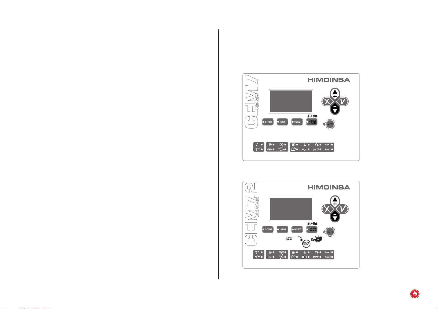
2. FRONT OF THE DISPLAY MODULE
The display module has a backlit display and various LEDs for monitoring the
status of the control unit. It also has keys that allow the user to control and
program the control unit.
CEM7 display module
CEM7P display module
FRONT OF THE DISPLAY MODULE | PAGE 6
Fig.1
Fig.2
1. Backlit display 4 lines by 20 digits.
2.1.2 CONTROL UNIT COMMAND BUTTONS
NOTE
The display goes into low power mode (backlight off) after 10 minutes have
passed without any keystroke.
2. Control unit buttons
• Buttons for control unit operating mode
• Control unit command buttons
• Display buttons
• Genset contactor activation button (only CEM7P module)
3. Status LEDs
• ENGINE status LEDs
• ALARMS LEDs
• CONTACTORS status LEDs
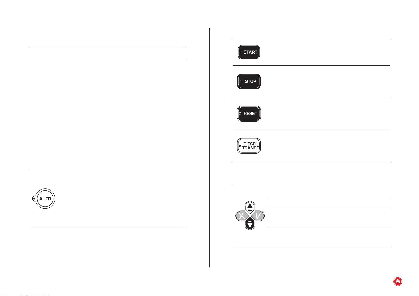
2.1 CONTROL UNIT BUTTONS
2.1.1 BUTTONS FOR CONTROL UNIT OPERATING MODES
Lit LED: Automatic
Automatic mode: The control unit
mode active
monitors the status of the genset and
manages its operation and the
programmable inputs.
LED flashing:
Automatic mode
blocked
Manual mode: The control unit is
commanded by the user.
LED off: Manual
mode active
Engine start button (only in manual mode)
Controls the start up with a single push.
Lit LED: Engine started.
Engine stop button (only in manual mode)
The rst press stops the engine following a cooling cycle. The
second press stops the engine immediately.
Lit LED: Engine stopping (with or without cooling)
Alarms reset button. Allows acoustic signals to be eliminated
and the user to report the alarms.
LED flashing: Pending notication alarms.
Lit LED: Alarms active.
Fuel transfer pump button.
In manual mode, this button activates the fuel transfer pump
if the fuel level is below the programmed limit.
Lit LED: Fuel transfer pump active.
2.1.3 DISPLAY BUTTONS
Confirm (V). Enter the menus and conrm the data
entered.
Cancel (X). Leave the menus and cancel the data entered.
Up (+). Advance through the selection on display screens,
the selection in maintenance menus and increase the
programming settings.
Down (-). Go back through the selection on display screens,
the selection in maintenance menus and decrease the
programming settings.
FRONT OF THE DISPLAY MODULE | PAGE 7
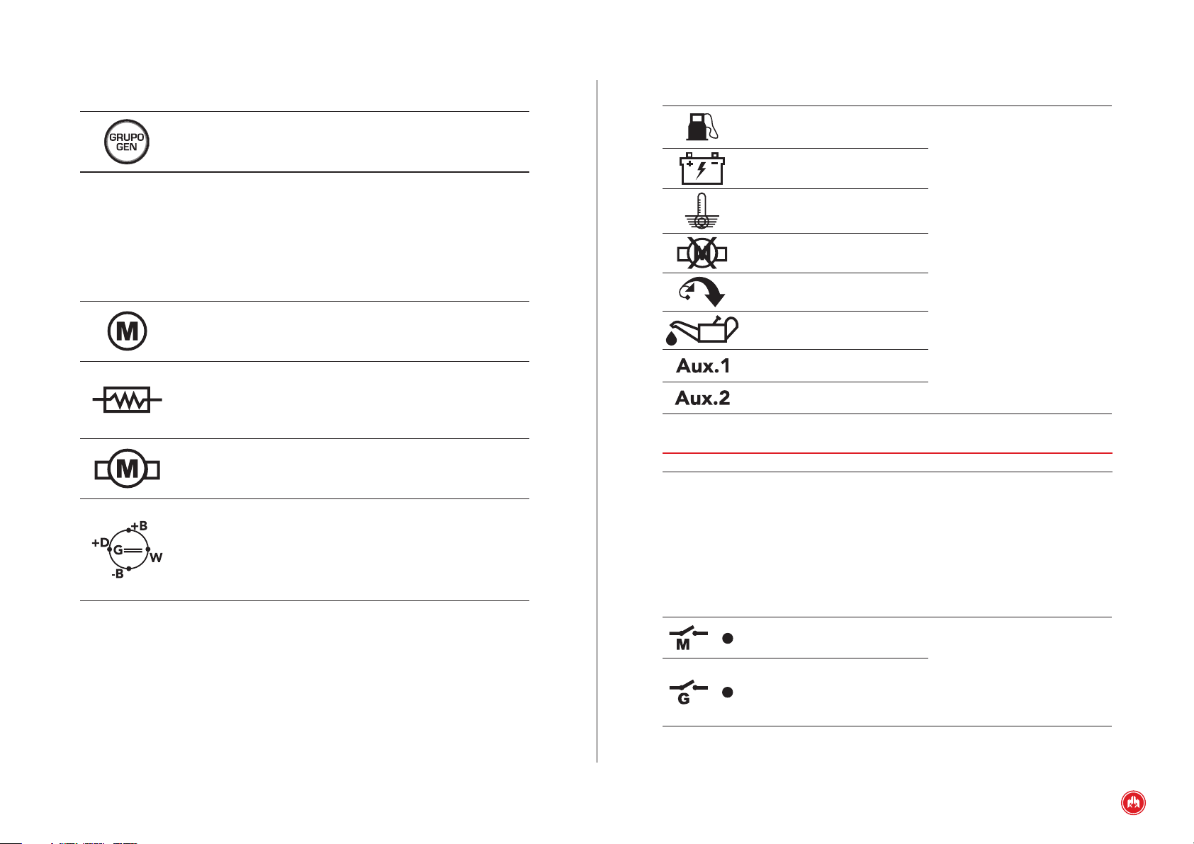
2.1.4 CONTACTOR BUTTONS (ONLY CEM7P MODULE)
2.2.2 ALARMS LEDS
Genset contactor. Enable/disable genset contactor (manual
mode only).
2.2 STATUS LEDS
2.2.1 ENGINE STATUS LEDS
Motor started
Preheating
Start engine
Alternator status
battery charging
Lit: Engine running detected
Off: Motor stopped
Lit: Engine preheating activated
Off: Engine preheating deactivated
Lit: Engine started
Off: Engine start deactivated
Lit: With engine running, voltage in the
battery charging alternator is detected
Off: Stopped engine or engine running
without voltage in the battery charging
alternator
Fuel reserve
Battery level
High temperature
Lit: Analogue sensor alarm
Engine start up failure
Overspeeding
Flashing: Digital sensor alarm
Off: Without alarm
Low oil pressure
Auxiliary 1 (freely
programmable)
Auxiliary 2 (freely
programmable)
NOTE
For more details see the Alarms section
2.2.3 CONTACTORS STATUS LEDS (CEM7 + CEA7CC2).
These LEDs only appear active when the switching control unit is connected.
Start up option due to Network Voltage Failure (CEM7 + CEA7CC2)
The M and G symbols on the front of the control unit only appear activated when
the switching control unit is connected.
Network contactor status
Genset contactor status
Lit: Contactor active
Flashing: Contactor in the
connection/disconnection
phase.
Off: Contactor disconnected.
FRONT OF THE DISPLAY MODULE | PAGE 8

2.3 PASSWORDS
The CEM7 control unit has 2 levels of 4-digit password to protect against
unauthorized access. The different levels of access are as follows:
• User (default password: 1111). User level access allows the operator
to access the main menu of the CEM7 control unit.
• Maintenance (default password: 1911). Maintenance level access
allows the operator to access the Parameters programming option
from the main menu.
The CEM7 control unit's passwords are customizable by the user from the main
menu. A user can congure both passwords for their access level and lower-level
passwords.
NOTE
To enter a password see Appendix II: password entry
FRONT OF THE DISPLAY MODULE | PAGE 9

3. OPERATING MODES
3.1 MANUAL MODE
In manual mode, the control unit is commanded by the user via the front panel of
the display module. The user can start and stop the engine by pressing the
START and STOP keys respectively.
Pressing the START key initiates the engine starting procedure (without
deactivating the network contactor CEM7 + CEA7CC2). Pressing the STOP key
initiates the engine stopping procedure with cooling; a second press of the STOP
key causes the engine to stop immediately without waiting for the cooling time.
x 1 click
WITH cooling
NOTE
In manual mode, the control unit's protection devices remain active, being able
to produce alarms that cause the motor to stop.
In manual mode, the control unit does not take into consideration the start
conditions (programmed, by external signal) that can be programmed.
Activation of the genset contactor on the CEM7P display module is performed by
pressing the GENSET key.
x 2 (double click)
WITHOUT cooling
OPERATING MODES | PAGE 10

In order to achieve activation of the genset contactor, the engine has to be
running and provide a stabilised electrical signal.
3.2 AUTOMATIC MODE
In automatic mode supervision of the installation is managed by the control
unit. Under certain conditions which can be programmed, the control unit starts
the genset to power the installation.
Programmable conditions for genset starting and activation of the genset
contactor include:
• External start (Settings table, parameter 10)
• Start programmed by schedule
• Forced operation signal (Settings table, parameter 12 and
Regulations table, parameter 25)
• Starting via the switching panel (CEA7CC2)
3.3 MODE LOCKING FUNCTION
Pressing the Auto or Man keys for 5 seconds activates the locking of the mode.
This control unit state is indicated by the ashing of the mode key currently
active. To deactivate the mode lock and allow normal operation of the control
unit, press the key associated to the active mode for 5 seconds.
5 ’’ Locked 5 ’’ Unlocked
Programmable conditions for genset starting without activation of the genset
contactor include:
• Tariff warning (Settings table, parameter 7)
• Engine test (Settings table, parameter 11)
Also in automatic mode it is possible to manage start ups by using external
devices (PC, modem, display modules or switching control units).
OPERATING MODES | PAGE 11

4. OPERATION
4.1 STARTING THE ENGINE
Under the conditions for activating the control unit, proceed to perform the
following engine start procedure:
4.1.1 DIESEL ENGINE
1. Start delay. Once activation conditions are detected, it is possible to program
a time delay (Times table, parameter 3) before continuing the engine start up
procedure only in automatic (CEM7 + CEA7CC2 or CEM7 + AE)
2. Preheating of the motor (PR). The control unit activates preheating output
(PR) for the programmed time (Times table, parameter 4). The control unit allows
programming of a temperature threshold (Thresholds table, parameter 48) of the
coolant sensor that interrupts the preheating process, before proceeding with
the engine start up.
3. Enabling the starting of the motor (positive contact activation). Enabling the
starting of the motor (positive contact activation) is performed via the
measurements module PC output. The output supports a Stop by De-energisation
conguration (output activation during engine operation) or Stop by Excitation
(engine stop pulse -Table times, - parameter 12). The operating mode of the
enabled output can be set (Times table, parameter 18).
OPERATION | PAGE 12

4. Starting the motor (ARR). For a maximum time (Times table, parameter 5),
the start output of the measurements module is activated while waiting to detect
at least one of the programmed start conditions. The possible engine starting
conditions are:
• Generator voltage (Regulations table, parameter 19). The motor is
considered started when a certain generator voltage is exceeded
(Threshold table, parameter 20).
• Alternator voltage (Regulations table, parameter 20). The motor is
considered started when a certain battery charging alternator voltage
is exceeded (Threshold table, parameter 21).
• Pickup frequency (Regulations table, parameter 21). The motor is
considered started when a certain pickup frequency is exceeded
(Threshold table, parameter 22). To activate the pickup calculation
via the engine ring gear, it is necessary to enter the number of teeth
on the engine's ywheel ring gear (Threshold table, parameter 24);
if the number of teeth for the ywheel ring gear is zero, the pickup
frequency is calculated via the generator frequency according to the
ratio 50 Hz / 1500 rpm, 50 Hz / 3000 rpm or 60 Hz /1800 rpm
(Regulations table, parameter 26).
• Low Oil Pressure Signal (Regulations table, parameter 22). Due to
its characteristics, it is not advisable to use the low oil pressure
signal to detect if the engine is running, but its use is recommended
as protection against a restart, as the engine is already running.
Exceptions to this engine start detection are SCANIA engines and
sensors that have their own power source.
4.1.2 GAS ENGINE
1. Checking the engine gas train (PR). The process of checking the gas train
begins with the activation of the PR output and lasts for a programmable
maximum time (Times table, parameter 4). If the control unit has a programmable
input (Settings table, parameter 25) assigned to the verication of the gas train,
the process checking the gas train shall end when activation of the gas train
verication input is detected; if gas train activation time ends without having
detected gas train verication, the control unit shall attempt the start again. If
the control unit has no input assigned to gas train verication (Settings table,
parameter 25, value 0), the control unit shall carry out the engine start after the
time set for checking the gas train. The gas train output PR will remain active
from the engine's start and running process until the engine stop is carried out.
2. Starting the motor (ARR). For a maximum time (Times table, parameter 5),
the start output of the measurements module is activated while waiting to detect
at least one of the programmed start conditions (Regulations table, parameters
19 to 22).
3. Gas Ignition (PC). Some time after (Times table, parameter 30) activating the
start signal, the PC output is activated to enable engine ignition once the residual
gas has been purged.
4. Gas valve. Some time after (Times table, parameter 31) activating the Gas
Ignition signal, the output congured as gas valve is activated (Settings table,
parameters 1 to 3, value 25).
5. If during the set time no motor starting is detected, the control unit waits for a
period of time (Times table, parameter 2) before retrying the start. Once a certain
number of starts has been exceeded without detecting any start condition (Times
table, parameter 1), the control unit activates the Starting Failure alarm.
6. During motor starting, the excitation of the battery charging alternator is
carried out through the D+ output for a period of time (Times table, parameter 8).
Once the excitation of the alternator has been completed, the measurement
module monitors the correct functioning of the battery charging alternator. In the
event a battery charging alternator failure is detected, the Alternator Failure
alarm is activated (Alarms table, parameter 10).
OPERATION | PAGE 13
7. Generator stabilisation. Once any start condition is detected, the control unit
waits for a xed time for stabilization of the generator signal before monitoring
the quality of the generator signal.
8. Nominal condition. After achieving engine stabilisation, verication of the
generator signal is performed. In this state, the quality of the signal produced by
the genset is evaluated (voltage levels, frequency,...).
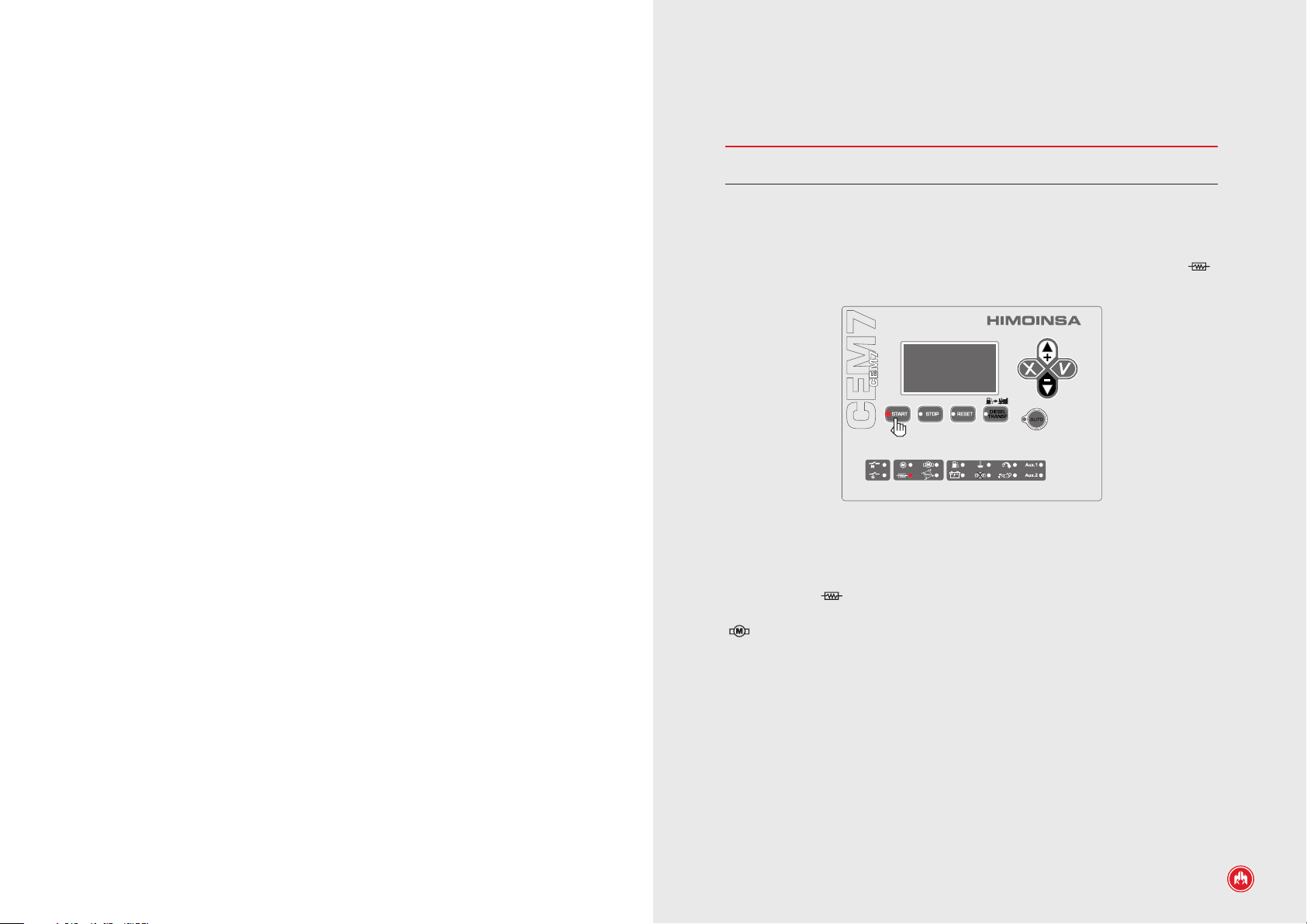
PRACTICAL EXAMPLE OF A START OPERATION
NOTE
Before starting the start cycle it is advisable to ensure the genset's main circuit
breaker is in the off position (OFF).
OPERATION
By pressing the START button the start cycle is initiated and is indicated by the
START button's LED switching on. At the same time if the motor has a preheating
plug the PR output is activated, with the corresponding LED switching on ( ),
for the programmed time. (1)
Fig.1
Once this time has elapsed the PR output is deactivated, and the corresponding
LED turns off ( ) and immediately the positive contact of the PC output is
activated and 0.5 seconds later the ARR output with the switching on of the LED
( ), this output remains activated until any engine running condition is
detected. (2)
OPERATION | PAGE 14
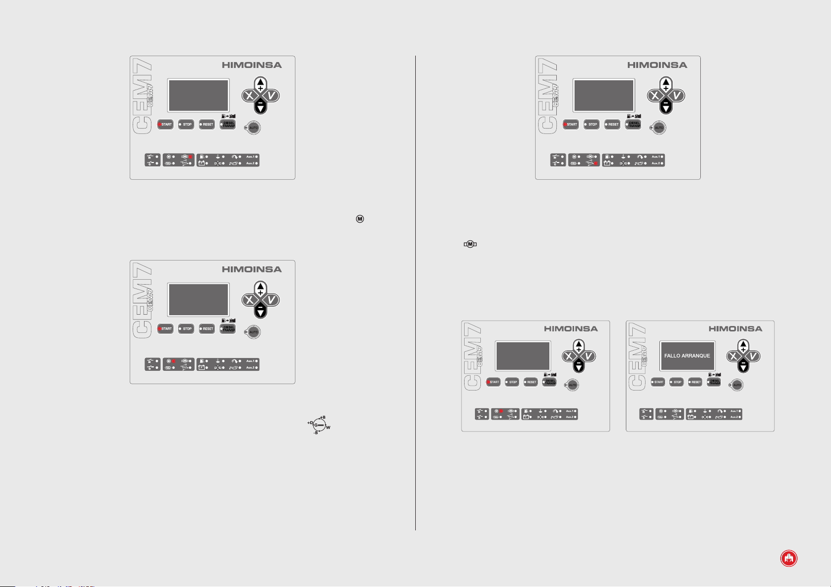
Fig.2
Fig.4
Once it has been detected that the engine is running the LED switches on ( ),
this indicates the end of the start cycle and the START button turns off. (3)
Fig.3
The LED corresponding to the battery charging alternator voltage ( ) switches
on when the voltage provided by the alternator exceeds the voltage threshold set
by default. (4)
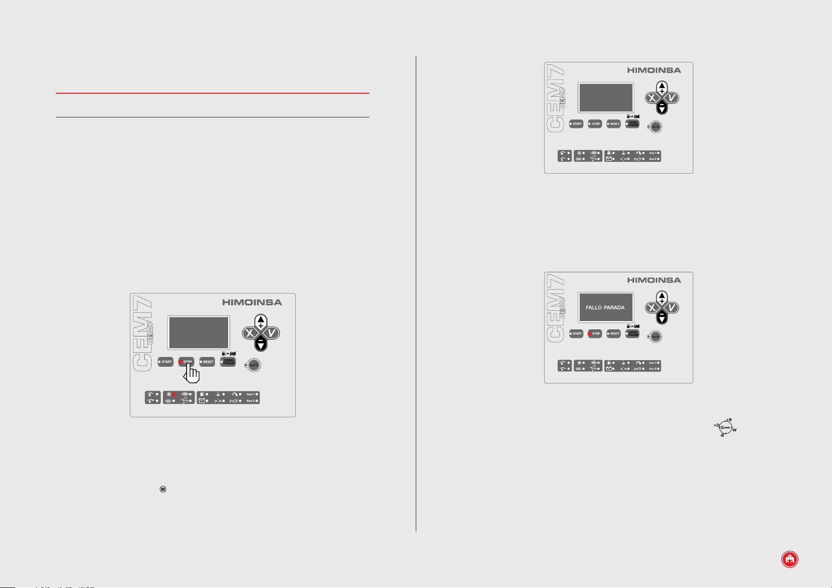
If during the start cycle, the engine started condition is not detected after 5
seconds, the ARR output deactivates and the corresponding LED turns off
( ). Subsequently the control unit automatically attempts a new start, repeating
a new cycle without the need to press START (4 cycles by default). After
exhausting the attempts to start the engine without success, the control unit
display shows the alarm (START FAILURE). (5)
To interrupt the start cycle just press the STOP button.
x4
Fig.5
OPERATION | PAGE 15

NOTE
The display shows the engine status screen, where the engine status is displayed
during the start up operation. This sequence is:
Genset: Stopped
Genset: Starting
Genset: Started
Genset: Stabilised
Genset: Charging
NOTE
The start an automatic system using a timer, external signal, etc. is carried out
following the same process as when starting manually.
• Pickup frequency (Regulations table, parameter 21). The engine is
considered stopped when the pickup frequency is below the start
up threshold (Threshold table, parameter 22). To activate the pickup
calculation via the engine ring gear, it is necessary to enter the
number of teeth on the engine's ywheel ring gear (Threshold table,
parameter 24); if the number of teeth for the ywheel ring gear is
zero, the pickup frequency is calculated via the generator frequency
according to the ratio 50 Hz / 1500 rpm, 50 Hz / 3000 rpm or 60 Hz
/1800 rpm (Regulations table, parameter 26).
• Low Oil Pressure Signal (Regulations table, parameter 22). The
low oil pressure condition is used for detecting a stop, by which the
engine is considered stopped when it is detected that the sensor is
closed. Exceptions to this engine stop detection are SCANIA engines
and sensors that have their own power source.
4.2 ENGINE STOP
The engine stopping process in automatic mode is carried out as follows:
4.2.1 DIESEL ENGINE
1. Cooling the motor. Once free of charging, the engine will continue running for
a cooling time (Times table, parameter 11). In certain situations, it is possible to
set the alarms (Alarms table, parameters 3, 6, 9...) of the control unit to perform
a stop without engine cooling
2. Engine stop. After the engine cooling time has elapsed, the PC output of the
measurements module is enabled or disabled according to the programmed
conguration (Regulations table, parameter 18). As an engine stop condition it is
possible to select:
• Generator voltage (Regulations table, parameter 19). The engine is
considered stopped when the generator voltage is below the start up
threshold (Threshold table, parameter 20).
• Alternator voltage (Regulations table, parameter 20). The engine is
considered stopped when the battery charging alternator voltage is
below the start up threshold (Threshold table, parameter 21).
4.2.2 GAS ENGINE
1. Checking the engine gas train (PR) and gas valve. The control unit
deactivates the gas supply outputs to the engine.
2. Gas Ignition (PC). Some time after (Times table, parameter 32) closing the
gas supply, the Gas Ignition output is deactivated to stop the engine. If the
engine stop is triggered by an emergency stop alarm, the Gas Ignition output is
deactivated simultaneously to cutting the gas supply.
To conrm the engine has stopped, all the programmed stop conditions must be
detected for a set period of time (Alarms table, parameter 71). If after 90
seconds an engine running condition continues to be detected, the Stop Failure
alarm is triggered.
OPERATION | PAGE 16
PRACTICAL EXAMPLE OF A STOP OPERATION
NOTE
Before starting the stop cycle it is advisable to ensure the genset's main circuit
breaker is in the off position (OFF).
The genset stop can be performed in various ways:
1. Manual: Pressing the STOP button once. To perform a stop with cooling cycle.
2. Manual: Pressing the STOP button twice. To perform a stop without cooling
cycle.
3. Turning the panel's activation key to the “O” position. To perform a stop
without cooling cycle.
4. Automatic: After cancelling the order which leads to the automatic start and
in this way performing a stop with cooling.
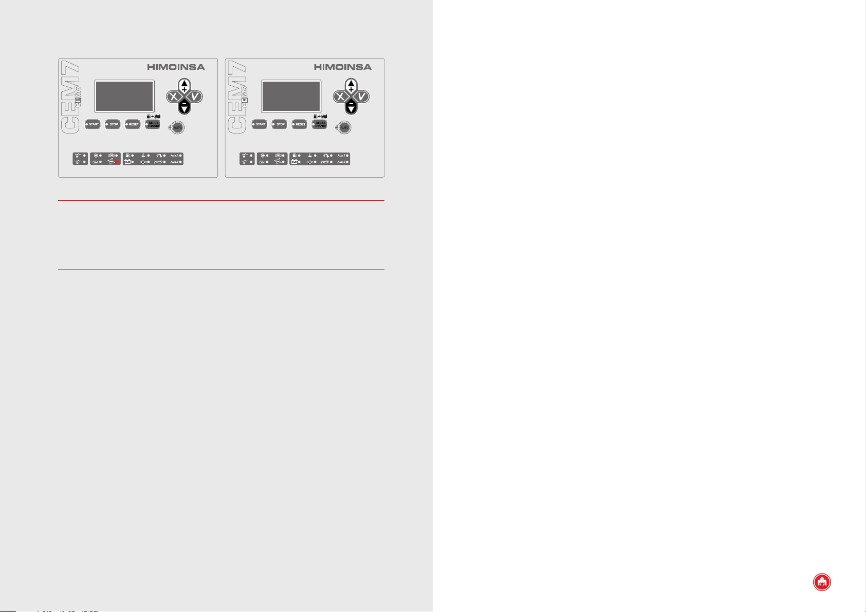
Sequence: We press the STOP button once and begin the stop cycle with engine
cooling. This is indicated with the STOP1 button lighting up.
Fig.2
If after a period of time any engine running condition is detected, the control unit
shows on the display the STOP FAILURE alarm and the LED of the STOP button
remains lit (3).
Fig.1
After concluding the cooling time (120 seconds by default), the PC output is
disabled or enabled according to the type of engine to carry out the stop, the
STOP button and the LED ( ) for the started engine switch off (2).
Fig.3
The LED corresponding to the battery charging alternator voltage ( ) switches
off when the voltage provided by the alternator falls below the programmed
voltage threshold (4).
OPERATION | PAGE 17
NOTE
The display shows the engine status screen, where the engine status is displayed
during the stop operation. This sequence is:
Genset: Stabilised
Genset: Cooling
Genset: Stopping
Genset: Stopped.
4.3 FUEL TRANSFER PUMP
It is possible to activate the fuel transfer pump of the CEM7 control unit by
associating its operation with the BT relay of the measurements module
(Regulations table, parameter 4). Once the fuel transfer pump option is enabled,
the operating mode is then set (Regulations table, parameter 1):
1. Inhibited mode. The fuel transfer pump is not managed.
2. Manual mode. The fuel transfer pump is activated by pressing the DIESEL
TRANSF key provided that the fuel level is below the maximum deactivation
threshold (Threshold table, parameter 19)
3. Automatic mode. Managing the fuel transfer pump works by monitoring the
minimum activation threshold (Threshold table, parameter 18) below which the
BT relay is connected and a maximum deactivation threshold (Threshold table,
parameter 19) above which the BT relay disconnects.
4. Combined mode. The combined mode of the fuel transfer pump manages the
fuel transfer pump according to the Automatic mode, but also allows activation of
the BT relay by pressing the diesel Transf. key. Manual activation of the BT relay
is limited by the maximum deactivation threshold (Threshold table, parameter
19). The combined mode of the fuel transfer pump is available for control units
with rmware versions 2.56 and above.
5. Control unit mode. Managing the fuel transfer pump is performed as follows:
• When the control unit is in automatic mode or test mode, the
operation of the fuel transfer pump is managed in automatic mode.
• When the control unit is in manual mode, the operation of the fuel
transfer pump is managed manually.
• When the control unit is in locked mode, the operation of the fuel
transfer pump is inhibited (CEM7 + CEA7CC2).
The control unit mode of the fuel transfer pump is available for control units with
rmware versions 2.54 and below.
OPERATION | PAGE 18

Calibration of the gauge: For correct fuel level measurements (required for
managing the fuel transfer pump and fuel level alarm) a calibration of the tank
gauge should be performed. This requires access to the minimum and maximum
gauge level parameters (Measurements table, parameters 12 and 13). To adjust
the minimum level of fuel in the tank validation of parameter 12 of the
Measurements table should be performed with the gauge in the minimum
position. To adjust the maximum level of fuel in the tank validation of parameter
13 of the Measurements table should be performed with the gauge in the
maximum position.
In the event the gauge response is not linear, it is possible to program a gauge
response curve with up to 8 points from the option MenuParametersSensors.
4.5 BATTERY CHARGING ALTERNATOR
The battery charging alternator is connected to the CEM7 control unit via the
digital output D + and the DI analogue input of the measurements module.
The CEM7 control unit can be congured to produce an Alternator Voltage alarm
(Alarms table, parameters 10 to 12) if a low voltage supplied by the battery
charging alternator is detected through the DI analogue input of the
measurements module.
It is possible to select (Regulations table, parameter 3) between 2 modes of
operation of the battery charging alternator:
4.5.1 ALTERNATOR MODE
4.4 HEATING
Management of engine heating allows 2 modes of activation:
• Assigning the heating function to BT relay of the measurements
module (Regulations table, parameter 4).
• Assigning the heating function to one of the 3 programmable outputs
of the measurements module (Settings table, parameters 1-3)
provided that the BT relay of the measurements module is assigned
to the management of the fuel transfer pump (Regulations table,
parameter 4).
Management of engine heating provides the following function:
• Below a certain engine temperature threshold (Threshold table,
parameter 29), the heating resistor is activated.
• Below a certain engine temperature threshold (Threshold table,
parameter 28), activation of the genset contactor is controlled
and the Low Engine Temperature Alarm is managed (Alarms table,
parameters 73 to 74) .
• Above a certain engine temperature threshold (Threshold table,
parameter 30), the heating resistor is deactivated.
Operation of the CEM7 control unit's battery charging alternator congured to
alternator mode, excites the alternator via a pulse with a congurable duration
(Times table, parameter 8) during engine start process through the D+ output of
the measurements module. At the end of the pulse, the control unit tests the
voltage generated by the battery charging alternator.
The voltage generated by the battery charging alternator can be used as an
engine running condition (Regulations table, parameter 20). For this purpose, the
control unit waits to measure voltage, via the DI analogue input, which is above
an alternator voltage detection threshold (Threshold table, parameter 21).
The CEM7 control unit can be congured to produce an Alternator Voltage alarm
(Alarms table, parameters 10 to 12) if a low voltage supplied by the battery
charging alternator is detected through the DI analogue input of the
measurements module if it is set to alternator mode.
OPERATION | PAGE 19

4.5.2 DYNAMO MODE
PROGRAMMING
Operation of the CEM7 control unit's battery charging alternator congured in
dynamo mode, excites the alternator via a continuous pulse through the D+
output of the measurements module while the engine is in start up phase or is
running.
The control unit congured in dynamo mode cannot use the voltage measured via
the DI analogue input for detecting an engine running condition.
The CEM7 control unit can be congured to produce an Alternator Voltage alarm
(Alarms table, parameters 10 to 12) if a low voltage supplied by the battery
charging alternator is detected through the DI analogue input of the
measurements module if it is set to alternator mode.
4.6 START/STOP KEY
The start/stop key in the ON position causes power to be supplied to the CEM7
control unit's electronic devices (measurements module and display module).
The start/stop key in the OFF position causes a controlled stop if it is running;
once the engine has stopped, power to the CEM7 control unit is disconnected.
4.7 START DUE TO LOAD DEMAND (ONLY CEA7CC2 EXPANSION)
The generator set will start operating, acquiring this load, when network power
consumption is detected which more than the limit set by parameter (Threshold
table, parameter 34). The genset will continue to operate until the genset power
consumption measured falls below a limit set by parameter (Thresholds table,
parameter 35). Both with the start and stop of the genset due to load demand,
the conditions must be validated for a programmable time (Times table,
parameter 27). The function of start up due to load demand is only enabled in
Automatic mode of the CEM7 control unit associated to a switching control unit
CEA7CC2.
NOTE
From the rmware versions of control units: Display 3.20 / Measurements 2.50
4.8 ELECTRONIC PROTECTION
DESCRIPTION
The electronic protection is a feature that permits a control unit output to be
activated in the event of an overload and short circuit alarm. This function allows
the genset's main circuit breaker to be disabled via the trip coil. While any of
these alarms that causes the engine to stop (immediate or cooling) remains
active or pending notication, the output assigned to electronic protection
remains active.
DESCRIPTION
This function enables automatic start up and activation of generator set charging
depending on the power consumption of the network.
The start up is performed according to the programming, considering the
maximum power (Threshold table, parameter 34) the network can consume for a
period of time (Times table, parameter 27). Once the generator set is started,
the system changes genset power leaving the network free of load.
When the load in the installation is below the programmed threshold (Threshold
table, parameter 35) for deactivation and the programmed period of time (Times
table, parameter 27) has elapsed, the system returns to charging the installation
via the network and the genset begins its stopping cycle.
PROGRAMMING
The possible outputs that can be assigned to this function are:
• The SC relay is assigned by default to this function. Furthermore, the
SC relay is also activated when any alarm is generated which causes
the engine to stop.
• The BT relay of the measurements module (Regulations table,
parameter 4).
• Any of the programmable outputs of the measurements module
(Settings table, parameters 1 to 3).
OPERATION | PAGE 20

4.9 MOTORPUMP MODE
4.10 GENSET IN RESERVE
DESCRIPTION
The motorpump mode congures the CEM 7 control unit to display only engine
measurements, hiding generator set voltage measurements. This conguration
must only be used for control units installed in motorpump type systems where
there is no electrical power generation. They must also disable all alarms
associated with the electrical measurements of the control unit and the detection
of the engine start up via generator voltage.
PROGRAMMING:
Enabling the motorpump mode is carried out through programming of a control
unit parameter (Screen table, parameter 6).
DESCRIPTION
The genset in reserve function allows the operation of several generator sets in
the same installation. In order to balance out the hours that all the gensets are
operational, this function lets the control units specify which generator set should
start up. They select the genset whose engine has been running for the least
length of time. This running mode only affects the control unit’s automatic
working mode. For safety reasons, a generator set can not start-up if any other
genset is detected to be starting-up with the functionality of the genset in reserve
enabled.
It is possible to combine the functionality of the genset in reserve with the
programmed weekly schedules (a timer switch expansion is required) in order to
establish priorities during specic periods of time. To do this, you have to
programme time slots in one of the gensets (the master genset) in the facility,
for:
• Forced start-up. During this period, the master genset will have
priority start-up and the facility’s genset in reserve will stop running,
once the master genset has started running.
• Star t-up inhibited. During this period, the master genset will not have
priority and therefore, the genset in reserve will start up. Once the
genset in reserve has started running, the master genset will stop.
PROGRAMMING
Enabling the genset in reserve function is performed by programming a control
unit parameter (Regulations table, parameter 31, values 4 to 7).
OPERATION | PAGE 21

5. CEM7 CONTROL UNIT INPUTS AND
IN: Input
OUT: Outputs
OUTPUTS
The CEM7 control unit's digital inputs, both those with a specic purpose as well
as those which are programmable, have a debounce time associated (Times table,
parameters 15-24) which requires that the value of the input is stable over a time
interval. Also, all of the CEM7 control unit's inputs can be congured to be active
with contact closed to earth or be inactive with contact closed to earth (Regulations
table parameters 5 to 15).
The status of the CEM7 control unit's inputs and outputs can be monitored from
the Main menu1.Inputs/Outputs. From that position, a screen displays the
status of the control unit's digital inputs and outputs:
* INPUTS/OUTPUTS *
IN:
OUT:
Index of the input/output. Ordered from 13 to 1
Detection of an active input is indicated by the following characters:
• IN 1. R: Fuel reserve (RC)
• IN 2. B: Low oil pressure (BPA)
• IN 3. A: High temperature (ATA)
• IN 4. N: Water level (NA)
• IN 5. X: Programmable input 4 (default value, external start)
(AE)
• IN 6. I: Programmable input 5 (default value, disabling start
up) (IA)
• IN 7. P: Emergency stop (PEM)
• IN 8. 1: Programmable input 1
• IN 9. 2: Programmable input 2
• IN 10. 3: Programmable input 3
• IN 11. S: Mushroom head emergency stop
• IN 12. M: Ignition key (MAN)
CEM7 CONTROL UNIT INPUTS AND OUTPUTS | PAGE 22
Detection of an active output is indicated by the following characters:
• OUT 1. A: Alarm active (AL)
• OUT 2. M: Motor started (MA)
• OUT 3. 1: Programmable output 1 (SAL 1)
• OUT 4. +: Battery charging alternator (D+)
• OUT 5. 2: Programmable output 2 (SAL 2)
• OUT 6. 3: Programmable output 3 (SAL 3)
• OUT 7. r: Network contactor (CRC, CRNA, CRNC)
• OUT 8. g: Genset contactor (CGC, CGNA, CGNC)
• OUT 9. B: Fuel transfer pump/heating resistor
(BTNA, BTA)
• OUT 10. 4: Electronic protection
• OUT 11. R: Preheating/Powered stop (PR)
• OUT 12. P: Unpowered stop/Powered stop (PC)
• OUT 13. C: Enabling control unit
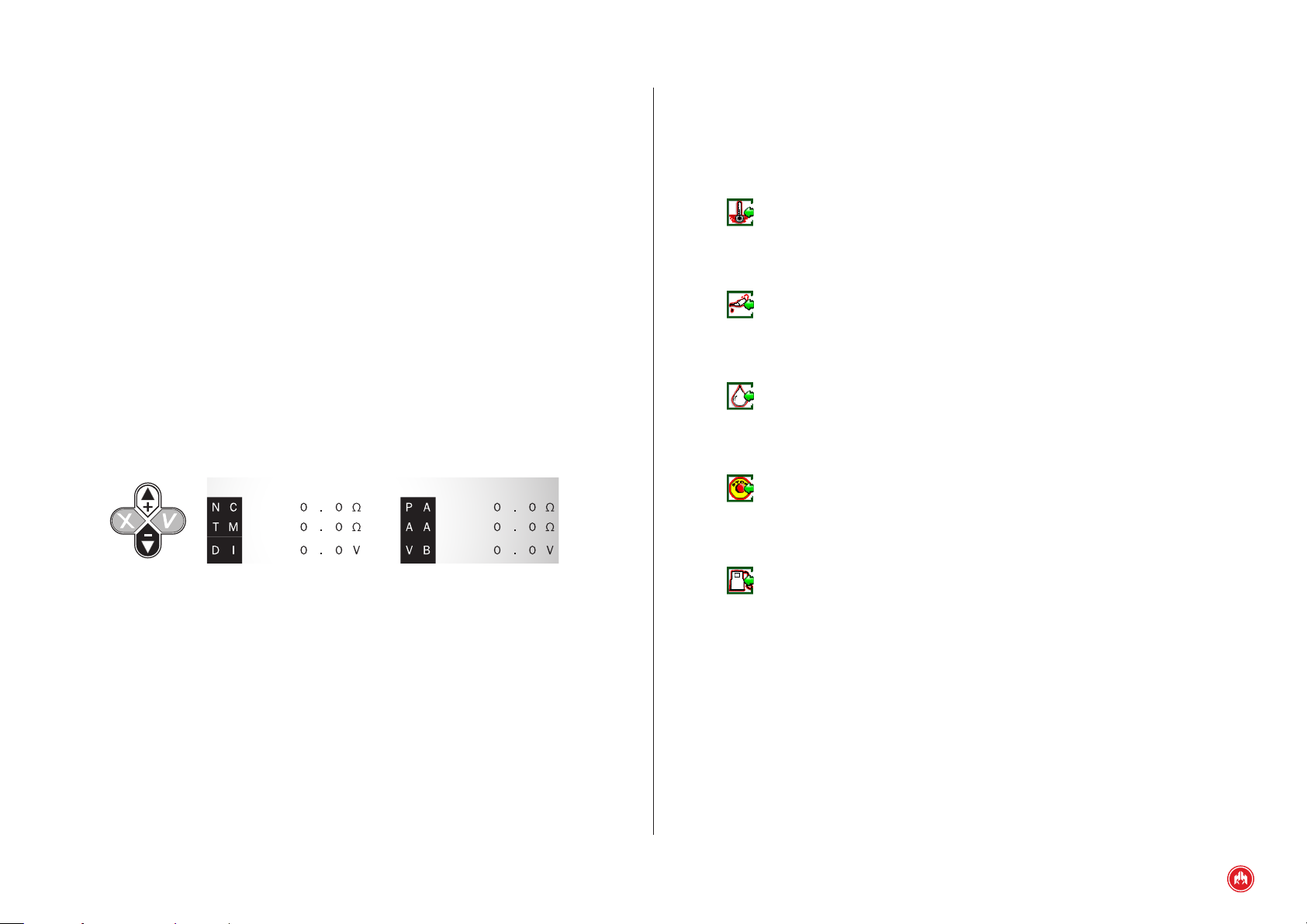
By pressing the up or down scroll keys it is possible to display the analogue
inputs.
5.1 DIGITAL INPUTS
The CEM7 control unit's measurements module has 5 digital inputs with
operation that is already preset.
The xed purpose inputs have the following behaviour:
HIGH TEMPERATURE (ATA)
Digital signal indicating to the control unit that an alarm has been generated due
to high engine temperature (Table Alarms, parameters 1-3).
LOW OIL PRESSURE (BPA)
Digital signal indicating to the control unit that an alarm has been generated due
to low oil pressure (Table Alarms, parameters 4 to 6).
WATER LEVEL (NA)
Digital signal indicating to the control unit that an alarm has been generated due
to low water level (Table Alarms, parameters 16 to 18).
ANALOGUE INPUTS
The value of the resistance analogue inputs is shown in ohms and the voltage
analogue inputs in volts. The various inputs displayed are:
• NC: Fuel level
• PA: Oil pressure
• TM: Engine temperature
• AA: Auxiliary analogue
• DI: Alternator voltage
• VB: Battery voltage
EMERGENCY STOP (PEM + SETA)
Digital signal indicating to the control unit that an immediate stop of the engine
must be performed without cooling
FUEL RESERVE (RC)
Digital signal indicating to the control unit that an alarm has been generated due
to the fuel reserve (Table Alarms, parameters 19 to 21).
CEM7 CONTROL UNIT INPUTS AND OUTPUTS | PAGE 23

5.2 PROGRAMMABLE INPUTS
The CEM7 control unit's measurements module has 5 digital inputs with
operation that can be programmed. The programmable inputs can be congured
to have the following behaviour:
TARIFF WARNING SIGNAL (EJP1)
This function is only managed in automatic mode of the control unit CEM7 +
CEA7CC2. The input congured as tariff warning (Settings table, parameter 7)
starts the genset after activating the corresponding input and after a set time
(Times table, parameter 9). Completion of the tariff ends when the input EJP1 is
disabled, stopping the engine with cooling.
TARIFF CHANGE SIGNAL (EJP2)
This function is only managed in automatic mode of the control unit CEM7 +
CEA7CC2. The input congured as tariff change (Settings table, parameter 8)
activates the genset contactor provided that no fault is found in the genset.
DISABLING START UP SIGNAL (IA + ENT5)
This function is only managed in automatic mode of the CEM7 control unit. The
input congured as disabling start up (Settings table, parameter 9) prevents the
genset from starting under any starting condition except in the case of forced start
up operation (Settings table, parameter 12) congured as high priority (Regulations
table, parameter 25).
EXTERNAL START SIGNAL (AE + ENT4)
This function is only managed in automatic mode of the CEM7 control unit. The
input congured as external start (Settings table, parameter 10) forces the start
up of the genset if it is in automatic mode, provided none of the following
conditions are present disabling start up:
• the control unit does not manage the disabling start up input (IA) or it
is not active.
• the control unit is not in lock mode programmed by time.
TEST SIGNAL (TEST)
This function is only managed in automatic mode of the CEM7 control unit with
the motorised circuit breaker option.
The input congured as test (Settings table, parameter 11) allows a check of the
genset to be performed without activation of the load.
FORCED OPERATION (MFOR)
This function is only managed in automatic mode of the CEM7 control unit.
The input congured as forced operation (Settings table, parameter 12) complies
with anti-re regulations according to which it should not stop the operation of
the genset under any condition except overspeeding and emergency stop
(whether this is alarm, external start up disabling input or programmed block). It
is possible to congure 3 modes of forced operation (Regulations table,
parameter 25):
• 0: Forced operation not enabled. The process of forced operation is
not managed despite having an associated programmable input.
• 1: Star ting due to network failure. Before activating the forced
operation input, the system waits for the start to occur due to a
programmed condition (alarms related to network signal, network
contactor failure, external start up...) needed to start the genset. To
stop the genset it is not sufcient that the start condition disappears,
but the input associated with the forced operation must be disabled.
• 2: Star ting due to forced operation. Before activating the forced
operation input, the genset starts immediately without the need to
wait for any other start condition to occur. To stop the genset, it is
necessary to switch to manual operating mode and in this mode
perform the stop using the control unit keyboard. Predominating the
stop button.
A delay in starting the genset can be congured through an external input via a
parameter (Regulations table, parameter 31).
CEM7 CONTROL UNIT INPUTS AND OUTPUTS | PAGE 24

PROGRAMMABLE ALARMS (AL1, AL2 AND AL3)
VERIFICATION OF GAS RAMP (S1 AND S2)
There are 3 programmable alarms available (Settings table, parameters 13, 14
and 15) that can be associated with any of the programmable inputs and which
serve the purpose of providing the control unit with additional alarms with
congurable operation (Alarms table, parameters 79 to 87). These alarms can be
programmed both with regards the mode of action as well as the text shown on
the display when activated.
PROGRAMMABLE ALARMS (AL4 AND AL5)
There are 2 additional programmable alarms available (Settings table, parameters
22 and 23) that can be associated with any of the programmable inputs and
which serve the purpose of providing the control unit with additional alarms with
congurable operation (Alarms table, parameters 111 to 116). These alarms can
be programmed both with regards the mode of action as well as the text shown
on the display when activated.
NOTE
From the rmware versions of control units: Display 3.20 / Measurements 2.50
SELECTION OF SET OF PARAMETERS (S1 AND S2)
There are 2 sets of additional parameters that can be enabled via any of the
programmable inputs (Settings table, parameters 16 and 17). Activating the
parameter set selection input enables the values with which the control unit
operates (Selector table).
GENSET CONTACTOR CONFIRMATION (CKG) (PHG7 REV 4.14 AND HIGHER)
The input congured as genset contactor conrmation (Settings table,
parameter 6) is used to verify the correct activation of the contactor. Upon
activation of the genset contactor, a time interval begins (Times table,
parameter 13) for verication of the contactor through the activation of the
genset contactor conrmation input. If after this time has elapsed there is no
conrmation of the activation of the genset contactor, a genset contactor alarm
is generated (Alarms table, parameter 101). If the control unit is operating in
automatic mode, a stop occurs with engine cooling. Similarly, if the genset
contactor conrmation input is detected as being active when the contactor is
not active, the start up of the generator set is inhibited.
The input congured to perform the gas train verication function (Settings table,
parameter 25) is used in gas engines (Regulations table, parameter 18, value 4)
to complete the testing process of the gas ramp and start the engine start up
process.
5.3 ANALOGUE INPUTS
The CEM7 control unit has 5 analogue inputs for measuring the engine operation
values. These analogue inputs characterize the operation of the engine to display
its status and produce alarms if necessary. By default, the alarms produced by
the analogue inputs do not stop the control unit (engine warnings), but can be
congured to perform this stop with or without cooling.
The CEM7 control unit performs a continuous check on the presence of the
analogue sensors installed, with the readings taken appearing on the display
module screen.
FUEL LEVEL INPUT (NC)
The fuel level analogue input indicates the amount of fuel remaining in the tank.
To adapt its operation it is necessary to adjust the maximum fuel tank value
(Measurements table, parameter 13) and the minimum fuel tank value
(Measurements table, parameter 12). To adjust go to section 4.3.
Also, it is possible to set a minimum fuel threshold in the tank (Thresholds table,
parameter 25) to cause an alarm warning (Alarms table, parameters 55-57) when
the fuel level is detected to be below this limit.
When the BT relay of the measurements module is programmed for managing the
fuel transfer pump, if the fuel level is detected to be below a lower limit
(Thresholds table, parameter 18) the fuel transfer pump is activated to provide
the tank with fuel. The deactivation of the fuel transfer pump occurs when fuel
level is detected to be above the programmable threshold (Thresholds table,
parameter 19). When the fuel transfer pump is in manual operation mode, this
upper threshold leads to the activation of the fuel transfer pump after the user
presses the relative button.
CEM7 CONTROL UNIT INPUTS AND OUTPUTS | PAGE 25

OIL PRESSURE INPUT (P)
AUXILIARY ANALOGUE INPUT (AA)
The oil pressure analogue input allows the engine oil pressure value to be
monitored. The control unit allows connection of VDO type sensors to the
analogue input. By setting a threshold a minimum oil pressure limit can be
established (Thresholds table, parameter 26) causing an alarm warning (Alarms
table, parameters 52 to 54) when the fuel level is detected to be below this limit.
ENGINE INPUT TEMPERATURE (T)
The engine temperature analogue input allows the engine water temperature
value to be monitored. The control unit allows connection of VDO type sensors to
the analogue input. By setting a threshold a maximum engine temperature limit
can be established (Thresholds table, parameter 27) causing an alarm warning
(Alarms table, parameters 49 to 51) when the temperature is detected to be
below this limit.
Also, provided heating management is programmed (either through the BT relay
or through any programmable output, provided that the BT relay is assigned to
the management of the fuel transfer pump), the engine temperature analogue
input is used to regulate the activation of the heating resistor.
The control unit allows a temperature threshold to be programmed (Thresholds
table, parameter 48) for the coolant sensor that interrupts the preheating
process during the start up of the engine.
ALTERNATOR VOLTAGE INPUT (DI)
The alternator voltage analogue input allows the voltage generated by the battery
charging alternator to be monitored. This input is used to diagnose possible
malfunctioning of the alternator if it detects a low voltage while the engine is
running; under these conditions, a battery alternator alarm (Alarms table,
parameters 10 to 12) is generated.
Also, this voltage can be programmed for detecting genset start up conditions
(Regulations table, parameter 20) via an alternator voltage threshold for the engine
when running (Thresholds table, parameter 21), provided it is not set in dynamo mode
(Regulations table, parameter 3).
The auxiliary analogue input is assigned by default to the supervision of the oil
temperature and can be programmed to be allocated to any other measurement
through a programmable curve (Analogue Sensors table).
ANALOGUE INPUTS EXPANSION
The CEM7 control unit allows you to add 8 analogue temperature inputs to the
PT100 sensor through the expansion of up to 2 CCPT100 devices. 2 maximum
temperature alarms can be added to each of these 4 analogue temperature
inputs with a P100 sensor.
The CEM7 control unit allows you to add 4 congurable analogue inputs (voltage
0 to 10 V, current 4 to 20 mA or resistive) through the expansion of the CCPT100
device. A congurable response curve, a descriptive text and the units displayed
in the user interface of the control unit can be associated to each of these 4
congurable analogue inputs.
5.4 PICKUP INPUT (PKC1, PKC2)
The measurements module pickup input measures the engine speed in
revolutions per minute (rpm). To calculate the speed it is necessary to enter the
number of teeth on the ywheel ring gear (Thresholds table, parameter 24). If
zero is entered as the number of teeth for the ywheel ring gear parameter, the
control unit is congured to not have a pickup sensor and calculate the rotational
speed from the frequency generated by the genset according to the ratio
50Hz/1500rmp, 50Hz/3000rpm or 60Hz/1800rmp or 60Hz/3600rpm
(Regulations table, parameter 26).
The CEM7 control unit can be congured to produce an overspeeding alarm
(Alarms table, parameters 22 to 24) as well as a under speed alarm (Alarms
table, parameters 25 to 27) depending on the mechanical speed provided by the
pickup.
CEM7 CONTROL UNIT INPUTS AND OUTPUTS | PAGE 26

5.5 PROGRAMMED DIGITAL OUTPUTS
The CEM7 control unit has 8 specic purpose outputs (2 relay outputs, 3 power
outputs and 3 digital outputs).
The functioning of these outputs is preset but can be congured.
PREHEATING OUTPUT. (PR). POWER OUTPUT
The preheating output (PR) of the CEM7 control unit is an output connected to a
high power shortable driver (70 A) which regulates the heating process of the
engine's spark plugs during the starting process. The activation time of the
preheating output can be set (Times table, parameter 4). The preheating output
can also be used to control stopping via the excitation of engines which use this
type of stop (Regulations table, parameter 18).
ENGINE STARTING OUTPUT. (ARR). POWER OUTPUT
The engine starting output (ARR) of the CEM7 control unit is an output connected
to a high power shortable driver (70 A) which activates the starter. The engine
starting output remains active until a programmed motor running condition is
detected (Regulations table, parameters 19 to 22) for a programmable maximum
time (Times table, parameter 5).
• Control PULL/HOLD. The engine start control set in PULL/HOLD
mode uses the PC engine stop output as a PULL signal which is
activated for a xed time of 1 second during starting. Any of the
programmable outputs (SAL1, SAL2 or SAL3) can be used as a HOLD
signal (Settings table, parameters 1 to 3, value 25) which remains
active during the time the engine is running.
FUEL TRANSFER PUMP/HEATING/ELECTRONIC PROTECTION OUTPUT (BT).
RELAY OUTPUT
The fuel transfer pump/heating output (BT) of the CEM7 control unit is a relay
output that can be congured (Regulations table, parameter 4) to manage the
fuel tank relling function through the fuel transfer pump or control the engine
heating process or electronic protection output for overload or short circuit.
The fuel transfer pump/heating output (BT) congured as electronic protection is
activated when the control unit detects excessive consumption (Thresholds
table, parameters 7 and 8) and activates an overload (Alarms table, parameters
28 to 30) or short circuit alarm (Alarms table, parameters 58 to 60).
EXCITATION OUTPUT OF THE BATTERY CHARGE ALTERNATOR (D+). DIGITAL
OUTPUT
ENGINE STOP OUTPUT. (PC). POWER OUTPUT
The engine stop output (ARR) of the CEM7 control unit is an output connected to
a high power shortable driver (70 A) which activates the stopping of the engine.
The congurable engine stop output (PC) can be congured so that it controls
engines with four different stop modes (Regulations table, parameter 18):
• Stop via de-energisation. The engine stop output congured as
a stop via de-energisation is activated 500 minutes after the
preheating output has been deactivated, which occurs when the
engine stop command has been given.
• Stop by excitation. The engine stop output congured as a stop by
excitation is activated for a programmable time interval (Times table,
parameter12) the engine stop command has been given.
• Stop by excitation/de-energisation. The engine stop output congured
as a stop by excitation/de-energisation is activated 500 minutes
after the preheating output has been deactivated, and is deactivated
when the engine stop command has been given. This output is used
to enable the engine sensors, with the preheating output involved in
performing the engine stop via the process of stopping by excitation.
The D+ output of the CEM7 control unit is responsible for exciting the battery
charging alternator during the starting process. This output can be congured
(Regulations table, parameter 3) to provide a start pulse (alternator mode) for a
programmable time interval (Times table, parameter 8) or keep the alternator
continuously energized (dynamo mode).
GENSET CONTACTOR OUTPUT (CG). RELAY OUTPUT
The genset contactor output (CG) of the CEM7 control unit is a relay output that
manages the closing and opening of the contactor. The activation of the genset
contactor can be congured to be continuous or via a pulse (Times table,
parameter 29)
CEM7 CONTROL UNIT INPUTS AND OUTPUTS | PAGE 27

ALARM OUTPUT (AL). DIGITAL OUTPUT
STARTED ENGINE OUTPUT (MA). DIGITAL OUTPUT
The alarm output (AL) is responsible for communicating the different states of
the CEM7 control unit. The AL output simultaneously activates the ashing of the
Reset key LED and display module buzzer of the CEM7 control unit. This output
monitors the following states of the CEM7 control unit:
• External start of the control unit. Before starting the control unit
when commanded by a programmable input associated with AE
mode, the control unit's alarm output (AL) is activated for 5 seconds.
The activation of the alarm output (AL) due to an external start of the
control unit can be inhibited (Regulations table, parameter31).
• Control unit errors. Given an error which is active or pending
notication by the user, control unit alarm output is activated for
a maximum programmable time (Times table, parameter 14). The
errors that activate the AL output are both alarms that cause the
engine to stop and warnings that do not cause the engine to stop.
Depending on how the AL output has been programmed (Regulations
table, parameter 31, acoustic alarm eld):
For an AL outlet that has been programmed as an acoustic signal (Regulations
table, parameter 31, acoustic alarm, eld value 0), when the user presses the
RESET key:
• Continuous activation of the AL output (value 0 in Times table,
parameter 14): the AL output is disabled, providing there is no active
error or warning.
• Timed activation (value in seconds of the activation of the output in
the Times table, parameter 14): the AL output is disabled the rst
time the RESET key is pressed or once the output activation time is
exceeded.
The started engine output (MA) of the CEM7 control unit is activated when any
started engine condition is detected and remains active while the engine is
running. The started engine output (MA) is deactivated as soon as the engine
stopping process begins; said process includes the engine cooling interval
(Times table, parameter 11) during the stopping process.
ELECTRONIC PROTECTION OUTPUT (SC). DIGITAL OUTPUT
The electronic protection output (SC) is activated when any alarm that stops the
engine is detected. The output remains activated until all the alarms that cause
the engine to stop disappear and are reported.
5.6 PROGRAMMABLE OUTPUTS
The CEM7 control unit has 3 programmable outputs with operation which can be
congured to indicate certain states (Settings table, parameters 1 to 3) and a
relay output (Settings table, parameter 4). The possible congurations that are
permitted with the programmable outputs are:
INHIBITED OUTPUT
The programmable outputs congured as inhibited output do not respond to any
action or state as they are permanently disabled.
When the AL output is programmed to signal errors (Regulations table, parameter 31, acoustic alarm eld, value 1), when the user presses the RESET key, the
buzzer of the interface is disabled but the AL output activation is maintained as
long as any active genset alarm remains in effect or pending notication.
OUTPUT PROGRAMMED ACCORDING TO THE STATE OF AN INPUT
The programmable outputs (associated with a programmable input) are activated
when an associated input is detected.
Possible congurations of associated inputs include the following values:
• Fuel reserve input
• Water level input
• Programmable input 1
• Programmable input 2
• Programmable input 3
CEM7 CONTROL UNIT INPUTS AND OUTPUTS | PAGE 28

• Programmable input 4
• Programmable input 5
PROGRAMMED OUTPUT FOR ALARM
parameter 26). The programmable output congured as programmed output for
dummy load is deactivated when higher genset power consumption than the
programmed threshold is detected (Thresholds table, parameter 33) during a set
time (Times table, parameter 26). As a condition for enabling the dummy load
output, the engine must be in a stabilized state.
The programmable outputs congured as a programmed output for alarm is
activated when the control unit detects an active alarm associated to a
programmable output or has not still not been notied by the user.
PROGRAMMED OUTPUT FOR FUNCTION
The programmable outputs congured as programmed output for function are
congured to allow a functionality associated to an output already used. Possible
congurations of functions include the following values:
• Heating resistor. The output programmed to function as heating
resistor activation if the BT relay is programmed to manage the fuel
transfer pump.
PROGRAMMED OUTPUT FOR MODE
The programmable outputs congured as a programmed output for mode is
congured to indicate the mode of operation of the control unit. Possible mode
congurations include the following values:
• Control unit in manual mode.
• Control unit in auto mode.
PROGRAMMED OUTPUT FOR DUMMY LOAD
DESCRIPTION
This function allows the activation of a loading bank which is separate to the
installation load, to avoid the generator set operating with low-load, in order to
prevent excessive oil consumption in the engine and allow it to run with an
optimal load.
PROGRAMMING
The programmable outputs congured as programmed output for dummy load is
activated when lower genset power consumption than the programmed threshold
is detected (Thresholds table, parameter 32) during a set time (Times table,
NOTE
From the rmware versions of control units: Display 3.20 / Measurements 2.50
PROGRAMMED OUTPUT FOR ENGINE HOLD CONTROL MODE
DESCRIPTION
This functionality activates for one second the PC output, simultaneously with the
programmed output in HOLD mode, in engines controlled in PULL/HOLD mode
(Regulations table, parameter 18, value 3). The programmed output in HOLD
mode remains active during engine operation.
For GAS engines (Regulations table, parameter 18, value 4), this functionality
allows the activation of the gas train at the installation.
PROGRAMMING
To activate the engine's PULL/HOLD control mode, a programmable output must
be assigned to the HOLD control function (Settings table, parameters 1 to 3,
value 25).
PROGRAMMED OUTPUT FOR STARTING DUE TO LOAD DEMAND
DESCRIPTION
This functionality allows the activation of an output when the power generated by
the generator set exceeds a programmable threshold for power generated by the
genset.
PROGRAMMING
With the generator set in operation, an output programmed with the load demand
start function will be activated (Settings table, parameters 1-4) when it is
detected that power consumption exceeds a programmed parameter limit
(Thresholds table, parameter 34). The output will remain active until the genset
power consumption falls below a programmed parameter limit (Thresholds table,
parameter 35). Both with the activation and deactivation of the load demand
CEM7 CONTROL UNIT INPUTS AND OUTPUTS | PAGE 29

output, the conditions must be validated for a programmable time (Times table,
parameter 27).
NOTE
From the rmware versions of control units: Display 4.49 / Measurements 4.01
DESCRIPTION
Programmable outputs can be congured to open the genset contactor for use
with motorized thermal-magnetic circuit breakers (Settings table, parameter 1 to
4, value 27). The output can be congured so that it is activated continuously or
in a timed mode via a pulse (Times table, parameter 29).
PROGRAMMED OUTPUT FOR GENSET/NETWORK CONTACTOR STATE (ONLY CEA7)
DESCRIPTION
The programmable outputs can be congured to monitor both the genset
contactor status and the network contactor status (only CEA control unit).
WATCHDOG PROGRAMMED OUTPUT
DESCRIPTION
The programmable outputs can be congured to monitor the status of the
electronics. The output remains active if the correct operation of the generator
set's control system is veried.
STABILIZED ENGINE PROGRAMMED OUTPUT
DESCRIPTION
Programmable outputs can be congured to monitor the stabilized engine status
(Settings table, parameters 1 to 4 or 24, value 96). The output remains active
once it detects the stabilized running condition of the engine after start-up (Times
table, parameter 7) including the cooling time during the stopping cycle.
NOTE:
Activation of the genset contactor is performed with a programmable time after
detecting that the engine is in operation (Times table, parameter 6), it being
possible to dephase the activation of the genset contactor and programmed
output in STABILIZED ENGINE mode.
PROGRAMMED FUMES CONTROL OUTPUT
DESCRIPTION
Programmable outputs can be congured to initiate the engine start-up process
with fumes control. This requires assigning a programmable output (Settings
table, parameters 1 to 4, value 97) that will be enabled during the start-up
process and will remain active for a programmable length of time (Times table,
parameter 33) once the engine is running.
5.7 EXPANSION PROGRAMMABLE OUTPUTS
The CEM7 control unit has 4 additional programmable outputs installed in the
Second Zero Suppression expansion, the operation of which can be congured to
indicate certain states (Settings table, parameters 18 to 21). Of the 4 outputs
available, 2 (Programmable outputs 4 and 5) of them are directly connected at
the terminal and the other 2 (programmable outputs 6 and 7) must be requested
as a special function. The possible congurations permitted by the programmable
outputs are the same as those explained in section 5.6 Programmable outputs.
PROGRAMMED GENSET CONTACTOR OPENING OUTPUT
CEM7 CONTROL UNIT INPUTS AND OUTPUTS | PAGE 30

6. CEM7 CONTROL UNIT ALARMS
1:
3: Total number of errors in the list
The CEM7 control unit has a list of alarms, the operation of which can be
congured so that actions are performed or so that they are shown on the display
module screen.
The CEM7 control unit distinguishes between errors that cause the engine to
stop (alarms) and errors do not cause the engine to stop (warnings).
Upon detection of an alarm or warning, the control unit produces an acoustic
signal, which activates the alarm digital output (AL) and the LED of the RESET
button and the display ashes; this condition will remain as long as the error
condition continues for a programmable maximum period of time (Times table,
parameter 14).
When there is an alarm, active warning or pending notication, the LED of the
RESET button remains illuminated. Pressing the RESET button allows the user to
view a list of alarms, active warnings and pending notication. To scroll through
the list of errors use the buttons on the display, the up button and down button.
Pressing the RESET button a second time noties the alarm.
The list of alarms, active warnings and pending notication has the following
format:
* ALARM *
MIN. GENSET FREQUENCY
E: Alarm / A: Warning
N: Pending notication
Position of the error in the list of errors
On the front of the control unit there are LEDs which indicate alarms detected by
digital sensors (digital inputs) or by analogue sensors (analogue inputs).
CEM7 CONTROL UNIT ALARMS | PAGE 31

NOTE
Alarms that cause the engine to stop are not auto-resettable, they must be
notied and reset so that the engine can be restarted, provided that the alarm
does not remain active.
The alarms produced by the analogue inputs do not cause the engine to stop,
just provide a warning in the default setting. They need to be reset to disappear
from the display, provided that the warning does not remain active, except for
the fuel level warning which is auto-resettable.
EXAMPLES OF ALARM OPERATIONS
• “EN” Alarm with engine stopped
• “AN” Warning that needs to be reset
• “A” Auto-resettable warning
“EN” ALARM WITH ENGINE STOPPED
1. Upon detection of an alarm or warning, the control unit produces an acoustic
signal, the LED of the RESET button and the display ashes and the alarm digital
output (AL) is activated. In this case the engine stops.
Fig.1
2. Pressing the RESET button eliminates the acoustic warning. The RESET LED
remains lit and the type of alarm is shown on the display (which stops ashing).
Ex: Alarm active “EN” High Water Temperature.
CEM7 CONTROL UNIT ALARMS | PAGE 32

ALARM
HIGH WATER
TEMPERATURE
Fig.2
3. We provide solutions for the alarm. In this case the temperature of the engine
when stopped must be lowered. We check the water level of the engine to detect
the cause of the anomaly. Once the alarm is no longer active "N", it can be reset
by pressing the RESET button and the engine can be put into operation again.
“AN” WARNING THAT NEEDS TO BE RESET, DOES NOT CAUSE THE ENGINE TO
STOP
1. Upon detection of an alarm or warning, the control unit produces an acoustic
signal, the LED of the RESET button and the display ashes and the alarm digital
output (AL) is activated.
ALARM
HIGH WATER
TEMPERATURE
Fig.1
2. Pressing the RESET button eliminates the acoustic warning. The RESET LED
remains LIT and the type of warning is shown on the display (which stops
ashing). Active warning “AN”.
NOTICE
HIGH WATER
TEMPERATURE
Fig.3
Fig.2
CEM7 CONTROL UNIT ALARMS | PAGE 33

3. We provide solutions for the warning. In this case, we stop the engine if we
believe this is necessary to detect the cause of the anomaly. Once the warning is
no longer active, "N" appears on the display and it can be reset by pressing the
RESET button.
NOTICE
HIGH WATER
TEMPERATURE
Fig.3
“A” AUTO-RESETTABLE WARNING
2. Pressing the RESET button eliminates the acoustic warning. The RESET LED
remains LIT and the type of warning is shown on the display (which stops
ashing). Warning “A”.
3. This type of warning is auto reset automatically whenever normal operating
conditions are restored. It focuses on the alarms related to the fuel level as part
of the default programming and the alarm corresponding to the network
thresholds.
WARNING
FUEL RESERVE
1. Upon detection of an alarm or warning, the control unit produces an acoustic
signal, the LED of the RESET button and the display ashes and the alarm digital
output (AL) is activated.
Fig.4
Fig.5
CEM7 CONTROL UNIT ALARMS | PAGE 34

6.1 LIST OF ALARMS
The list of active alarms and warnings can be grouped as follows (according to
the MANUFACTURER'S DEFAULT SETTINGS)
6.1.1 ENGINE ALARMS
Table 1
Description of the engine alarms
Description Front LED Type Action
Low engine temperature Notice Not for engine
Unit signal failure Alarm
Engine communication
(only CEM7J option)
Temperature Warning
(only expansion PT100)
Notice Not for engine
Engine stops with
cooling
Description Front LED Type Action
High water temperature Flashing LED alarm
Low oil pressure Flashing LED alarm
Emergency Stop alarm
Battery charging alternator
failure (with engine
running)
Starting failure Flashing LED
Low water level Flashing LED alarm
Fuel reserve Flashing LED warning Not for engine
Overspeeding Lit LED alarm
Under Speed alarm
Low battery voltage Notice Not for engine
High water temperature by
sensor
Low oil pressure by sensor Lit LED Notice Not for engine
LED off warning Not for engine
Lit LED Notice Not for engine
Engine stops immediately without cooling
Engine stops immediately without cooling
Engine stops immediately without cooling
Engine stops immediately without cooling
Engine stops immediately without cooling
Engine stops with
cooling
6.1.2 GENERATOR ALARMS
Table 2
Description of the generator alarms
Description Type Action
Overload Alarm Genset stops with cooling
Genset voltage asymmetry Alarm Genset stops with cooling
Maximum genset voltage Alarm Genset stops immediately without cooling
Maximum genset frequency Alarm Genset stops immediately without cooling
Incorrect genset phases sequence Alarm Genset stops with cooling
Reverse Power Alarm Genset stops with cooling
Short Circuit Alarm Genset stops with cooling
Minimum genset voltage Alarm Genset stops with cooling
Minimum genset frequency Alarm Genset stops with cooling
6.1.3 ALARMS ASSOCIATED WITH PROGRAMMABLE INPUTS
There are three free programmable alarms that can be associated with engine
alarms and they can be reected on the display via LEDS Aux1 and Aux2.
Low fuel level by sensor Lit LED Notice
Unexpected stop
Stop failure
Not for engine
CEM7 CONTROL UNIT ALARMS | PAGE 35

6.2 DESCRIPTION OF THE ALARMS
Table 3
Description of the alarms associated with programmable inputs
Description Type Action
Associated with programmable inputs Alarm According to conguration
Conrmation of Contactor Alarm Engine stopped
The high water temperature alarm is set by default (Alarms table, parameter 3) to
always perform an immediate stop of the engine.
NOTE
In the CEM7J option the ATA input can be assigned to a programmable alarm. In
this case, the alarm detection is performed by the engine's CIU and transmitted
by the communication bus J1939.
All alarms except those which are non-programmable, can be congured as
follows:
To be activated:
• Never
• Always
• During the start up of the engine
• From detection that the engine has started
• From the nominal condition of the engine
To perform one of the following actions:
• Not perform any actions (warning)
• Stop the engine with cooling of the engine
• Perform an immediate stop of the engine
The default conguration of each of the alarms will be highlighted.
HIGH WATER TEMPERATURE
The CEM7 control unit's high water temperature alarm is associated with the
digital input specically for the high water temperature (ATA) or errors detected by
the engine's CIU (only CEM7J option). The status of this input must be validated
during a time interval (Times table, parameter 17) for stabilisation (debounce)
before generating the high water temperature alarm.
It can be congured as normally open or normally closed (Regulations table,
parameter 7). Detection of the high water temperature alarm is set by default
(Alarms table, parameter 1) to always be active.
LOW OIL PRESSURE
The CEM7 control unit's low oil pressure alarm is associated with the digital
input specically for the low oil pressure (BPA) or errors detected by the engine's
CIU (only CEM7J option). The status of this input must be validated during a time
interval (Times table, parameter 16) for stabilisation (debounce) before
generating the low oil pressure alarm.
It can be congured as normally open or normally closed (Regulations table,
parameter 6).
The low oil pressure alarm is set by default (Alarms table, parameter 4) to be
activated when it is detected that the engine has been started.
A low oil pressure alarm can be associated with a time (Alarms table,
parameter 5) to delay the moment at which the alarm begins to conrm the alarm
conditions.
The low oil pressure alarm is set by default (Alarms table, parameter 6) to always
perform an immediate stop of the engine.
NOTE
In the CEM7J option the BPA input can be assigned to a programmable alarm. In
this case, the alarm detection is performed by the engine's CIU and transmitted
by the communication bus J1939.
A high water temperature alarm can be associated with a time (Alarms table,
parameter 2) to delay the moment at which the alarm begins to conrm the alarm
conditions.
CEM7 CONTROL UNIT ALARMS | PAGE 36

EMERGENCY STOP (ACTION NOT PROGRAMMABLE)
The CEM7 control unit's emergency stop alarm is associated with the digital
input specically provided for emergency stops (PEM).
It can be congured as normally open or normally closed (Regulations table,
parameter 11).
Similarly, the emergency stop alarm is also associated with the SETA input of the
measurements module; said input cuts power to the power outputs of the
measurements module (stops engine) ensuring the engine shutdown is set as
stop via de-energisation (Regulations table, parameter 18) independently of the
control unit's electronics. With engines set to stop while powered, the input must
be earthed.
The emergency stop alarm always executes the engine shutdown without cooling.
It is not possible with this action to associate any delay time, set to engage
immediately after detecting the emergency stop input (PEM).
STARTING FAILURE
The CEM7 control unit's starting failure alarm is generated if the number of
consecutive retries (Times table, parameter 1) and failures is exceeded during
engine start. Between each start attempt a programmable delay is observed
(Times table, parameter 2). Once the alarm has been generated the control unit
waits for the notication by the user before retrying the engine starting process.
LOW WATER LEVEL
The CEM7 control unit's low water level alarm is associated with the digital input
specically for the low water level (NA) or errors detected by the engine's CIU
(only CEM7J option). The status of this input must be validated during a time
interval (Times table, parameter 18) for stabilisation (debounce) before
generating the low water level alarm.
It can be congured as normally open or normally closed (Regulations table,
parameter 8).
BATTERY CHARGING ALTERNATOR FAILURE
The CEM7 control unit's battery charging failure alarm is associated with the
analogue input for the battery charging alternator voltage (DI). The voltage
measured via said input must exceed the voltage threshold for detecting that the
engine has started (Thresholds table, parameter 21); otherwise, this battery
alternator failure alarm is activated.
The battery alternator failure alarm is set by default (Alarms table, parameter 10)
to be activated when it is detected that the engine has been started.
A battery alternator failure alarm can be associated a debounce time (Alarms
table, parameter 11) during which the voltage measured via the DI input must be
kept below the detection threshold for the started engine as a condition causing
the activation of the battery alternator failure alarm.
The battery alternator failure alarm is set by default (Alarms table, parameter 12)
to perform no action (warning).
Detection of the low water level alarm is set by default (Alarms table,
parameter 16) to always be active.
A low water level alarm can be associated with a time (Alarms table,
parameter 17) to delay the moment at which the alarm begins to conrm the
alarm conditions.
The low water level alarm is set by default (Alarms table, parameter 18) to always
perform an immediate stop of the engine if it is not already stopped.
NOTE
In the CEM7J option the NA input can be assigned to a programmable alarm. In
this case, the alarm detection is performed by the engine's CIU and transmitted
by the communication bus J1939.
CEM7 CONTROL UNIT ALARMS | PAGE 37

FUEL RESERVE
The CEM7 control unit's fuel reserve alarm is associated with the digital input
specically provided for the fuel reserve (RC). The status of this input must be
validated during a time interval (Times table, parameter 15) for stabilisation
(debounce) before generating the fuel reserve alarm.
It can be congured as normally open or normally closed (Regulations table,
parameter 5).
Detection of the fuel reserve alarm is set by default (Alarms table, parameter 19)
to always be active.
A fuel reserve alarm can be associated with a time (Alarms table, parameter 20)
to delay the moment at which the alarm begins to conrm the alarm conditions.
The fuel reserve alarm is set by default (Alarms table, parameter 21) to perform
no action (warning).
User intervention is not required to reset the generator set after a low fuel alarm
has been generated (auto reportable alarm).
UNDER SPEED
The CEM7 control unit's under speed alarm is associated with the measurement
of the engine ywheel ring gear's rotation speed or through the J1939 channel of
communication with the engine (only CEM7J option). This measurement is
performed via the pickup input of the measurements module. Alarm management
is limited to the fact that the parameter for the number of teeth on the ywheel
ring gear (Thresholds table, parameter 24) is not zero.
Detection of the under speed alarm is set by default (Alarms table, parameter 25)
to be activated under nominal engine conditions.
An under speed alarm can be associated a debounce time (Alarms table,
parameter 26) during which it must be kept below the minimum threshold set
(Thresholds table, parameter 12).
The under speed alarm is set by default (Alarms table, parameter 27) to always
perform a stop of the engine with cooling.
OVERLOAD
OVERSPEEDING
The CEM7 control unit's overspeeding alarm is associated with the measurement
of the engine ywheel ring gear's rotation speed or through the J1939 channel of
communication with the engine (only CEM7J option). This measurement is
performed via the pickup input of the measurements module. Alarm management
is limited to the fact that the parameter for the number of teeth on the ywheel
ring gear (Thresholds table, parameter 24) is not zero.
Detection of the overspeeding alarm is set by default (Alarms table, parameter 22)
to be activated under nominal engine conditions.
An overspeeding alarm can be associated a debounce time (Alarms table,
parameter 23) during which the ring gear rotation speed must be kept above the
maximum rotation speed limit (Thresholds table, parameter 11).
The overspeeding alarm is set by default (Alarms table, parameter 24) to always
perform an immediate stop of the engine.
The CEM7 control unit's overload alarm is associated with the measurement of
the RMS current in any phase which exceeds the maximum overload limit
programmed (Thresholds table, parameter 7) but which is lower than the
maximum short circuit limit (Thresholds table, parameter 8).
The phases which are evaluated for the detection of the overload alarm are
selected depending on the conguration of the installation phases (Thresholds
table, parameter 1):
• In a single phase conguration phase 1 is tested.
• In a two-phase conguration phases 1 and 2 are tested.
• In a three-phase conguration with neutral or three-phase without
neutral phases 1, 2 and 3 are tested.
Detection of the overload alarm is set by default (Alarms table, parameter 28) to
be activated under nominal engine conditions. An overload alarm can be
associated a debounce time (Alarms table, parameter 29) during which the
current measured in a particular phase must be kept above the maximum
threshold limit programmed (Thresholds table, parameter 7). The overload alarm
is congured by default (Alarms table, parameter 30) to perform a stop of the
engine with cooling.
CEM7 CONTROL UNIT ALARMS | PAGE 38

GENSET VOLTAGE ASYMMETRY
The CEM7 control unit's genset voltage asymmetry alarm is associated with the
fact that the difference between any two RMS voltages between genset voltage
phases (VG12, VG23 or VG31) exceeds the maximum asymmetry limit
programmed (Thresholds table, parameter 4).
The voltage asymmetry alarm is activated only when the control unit is congured
to measure the voltage of three-phase with neutral or three-phase without
neutral. Detection of the genset voltage asymmetry alarm is set by default
(Alarms table, parameter 31) to be activated under nominal engine conditions.
The CEM7 control unit's genset voltage asymmetry alarm can be associated a
rebounce time (Alarms table, parameter 32) during which the difference between
any two values of genset phase voltage (VG12, VG23 or VG31) should be kept
above the maximum limit set (Thresholds table, parameter 4). The genset voltage
asymmetry alarm is set by default (Alarms table, parameter 33) to always perform
a stop of the engine with cooling.
MAXIMUM GENSET FREQUENCY
The CEM7 control unit's maximum genset frequency alarm is associated with the
condition that the frequency generated by the genset is above the maximum
frequency limit set (Thresholds table, parameter 5).
The measurement of genset frequency is carried out on the rst phase. If in that
phase no signal is detected, the frequency measurement is then carried out on
the second phase. Likewise, if in that phase no signal is detected either, the
frequency measurement is then carried out on the third phase.
Detection of the maximum genset frequency alarm is set by default (Alarms
table, parameter 37) to be activated under nominal engine conditions.
A maximum genset frequency alarm can be associated a debounce time (Alarms
table, parameter 38) during which the frequency must be kept above the
maximum threshold limit set (Thresholds table, parameter 5). The maximum
genset frequency alarm is set by default (Alarms table, parameter 39) to perform
an immediate stop of the engine.
MAXIMUM GENSET VOLTAGE
The CEM7 control unit's maximum genset voltage alarm is associated with the
condition that the measurement of the genset's RMS voltage is above the
maximum voltage limit set (Thresholds table, parameter 2).
The phases which are evaluated for the detection of the maximum genset voltage
alarm are selected depending on the conguration of the installation phases
(Thresholds table, parameter 1):
• In a single phase conguration voltage V1N is tested.
• In a two-phase conguration voltage V12 is tested.
• In a three-phase conguration with neutral or three-phase without
neutral, phases V12, V23 and V13 are tested.
Detection of the maximum genset voltage alarm is set by default (Alarms table,
parameter 34) to be activated under nominal engine conditions. A maximum
genset voltage alarm can be associated a debounce time (Alarms table,
parameter 35) during which the voltage must be kept above the maximum
threshold limit set (Thresholds table, parameter 2). The maximum genset voltage
alarm is set by default (Alarms table, parameter 36) to perform an immediate stop
of the engine.
INCORRECT GENSET PHASES SEQUENCE
The CEM7 control unit’s incorrect genset phases sequence alarm is associated
to the fact that the genset voltage inputs of each phase are in order (phases 123
for direct conguration of sequences —value 0, Regulations table, parameter
34— or phases 321 for inverse conguration of sequences —value 1,
Regulations table, parameter 34—).
The incorrect genset phases sequence alarm is only enabled when the control
unit is congured to work three-phase with neutral or three-phase without neutral.
Detection of the incorrect genset phase sequence alarm is set by default (Alarms
table, parameter 40) to be activated: From the rated condition of the engine.
An incorrect genset phases sequence alarm can be associated a debounce time
(Alarms table, parameter 41) during which an incorrect order in the maximum
genset voltages must be detected.
The incorrect network phases sequence alarm is set by default (Alarms table,
parameter 42) to: Stop the engine with cooling of the engine.
CEM7 CONTROL UNIT ALARMS | PAGE 39

REVERSE POWER
The CEM7 control unit's reverse power alarm is activated when the power
measured for the genset is negative and greater than the value resulting from
calculating the factor programmed as a percentage (Thresholds table,
parameter 10) of the nominal power (Thresholds table, parameter 9).
Sometimes the reverse power alarm may be due to the incorrect wiring of the
current transformers.
Detection of the reverse power alarm is set by default (Alarms table,
parameter 43) to be activated under nominal engine conditions.
A reverse power alarm can be associated a debounce time (Alarms table,
parameter 44) during which the power measured must be outside the
programmed limit.
The reverse power alarm is set by default (Alarms table, parameter 45) to perform
a stop of the engine with cooling.
HIGH WATER TEMPERATURE BY SENSOR
The CEM7 control unit's high water temperature by sensor alarm is associated
with the analogue input for the water temperature (T). The high water temperature
by sensor alarm is activated when a higher temperature is detected than the
programmed limit (Thresholds table, parameter 27).
Detection of the high water temperature alarm by sensor is set by default (Alarms
table, parameter 49) to always be active.
A high water temperature by sensor alarm can be associated a debounce time
(Alarms table, parameter 50) during which it must be detected that the water
temperature is above the limit set (Thresholds table, parameter 27).
The high water temperature by sensor alarm is set by default (Alarms table,
parameter 51) to perform no action (warning).
LOW OIL PRESSURE BY SENSOR
LOW BATTERY VOLTAGE
The CEM7 control unit's low battery voltage alarm is activated when the battery
voltage measured falls below a set limit (Thresholds table, parameter 17).
Detection of the low battery voltage alarm is set by default (Alarms table,
parameter 46) to always be active.
A low battery voltage alarm can be associated a debounce time (Alarms table,
parameter 47) during which it must be detected that the battery voltage is below
the limit set (Thresholds table, parameter 17).
The low battery voltage alarm is set by default (Alarms table, parameter 48) to
perform no action (warning).
The CEM7 control unit's low oil pressure by sensor alarm is associated with the
analogue input for the oil pressure (T). The low oil pressure by sensor alarm is
activated when lower pressure is detected than the programmed limit (Thresholds
table, parameter 26).
The low oil pressure by sensor alarm is set by default (Alarms table, parameter 52)
to be activated when it is detected that the engine has been started.
A low oil pressure alarm can be associated a debounce time (Alarms table,
parameter 53) during which it must be detected that the oil pressure is below the
limit set (Thresholds table, parameter 26).
The low oil pressure alarm is set by default (Alarms table, parameter 54) to
perform no action (warning).
CEM7 CONTROL UNIT ALARMS | PAGE 40

LOW FUEL LEVEL BY SENSOR
HIGH BATTERY VOLTAGE
The CEM7 control unit's low fuel level by sensor alarm is associated with the
analogue input for the fuel level (NC). The low fuel level by sensor alarm is
activated when the fuel level detected is lower than the programmed limit
(Thresholds table, parameter 25).
Detection of the low fuel level alarm is set by default (Alarms table, parameter 55)
to always be active.
A low fuel level alarm can be associated a debounce time (Alarms table,
parameter 56) during which it must be detected that the fuel level is below the
limit set (Thresholds table, parameter 25).
The low fuel level alarm is set by default (Alarms table, parameter 57) to perform
no action.
User intervention is not required to reset the generator set after a low fuel level
by sensor alarm is generated (auto reportable alarm).
LOW AUXILIARY BATTERY VOLTAGE
The CEM7 control unit's low auxiliary battery voltage alarm is activated when the
voltage measured for the battery connected to the Second zero expansion falls
below a set limit (Thresholds table, parameter 31).
Detection of the low auxiliary battery voltage alarm is set by default (Alarms
table, parameter 117) to never be active.
A low auxiliary battery voltage alarm can be associated a debounce time (Alarms
table, parameter 118) during which it must be detected that the battery voltage
is below the limit set (Thresholds table, parameter 31).
The CEM7 control unit's high battery voltage alarm is activated when the battery
voltage measured is above a set limit (Thresholds table, parameter 36).
Detection of the high battery voltage alarm is set by default (Alarms table,
parameter 120) to never be active.
A high battery voltage alarm can be associated a debounce time (Alarms table,
parameter 121) during which it must be detected that the battery voltage is
above the limit set (Thresholds table, parameter 36).
The high battery voltage alarm is set by default (Alarms table, parameter 122) to
perform no action (warning).
LOW BATTERY VOLTAGE WHEN STARTING
The CEM7 control unit's low battery voltage when starting alarm is activated
when the battery voltage measured is below a set limit (Thresholds table,
parameter 37).
Detection of the low battery voltage when starting alarm is set by default (Alarms
table, parameter 123) to always be active and cannot be modied.
A low battery voltage when starting alarm can be associated a debounce time
(Alarms table, parameter 124) during which it must be detected that the battery
voltage is below the limit set (Thresholds table, parameter 37).
The low battery voltage alarm is set by default (Alarms table, parameter 125) to
perform no action (warning).
The low auxiliary battery voltage alarm is set by default (Alarms table,
parameter 119) to perform no action.
CEM7 CONTROL UNIT ALARMS | PAGE 41

SHORT CIRCUIT
The CEM7 control unit's short circuit alarm is associated with the condition that
the measurement of the RMS current is above the maximum short circuit limit
set (Thresholds table, parameter 8).
The phases which are evaluated for the detection of the short circuit alarm are
selected depending on the conguration of the installation phases (Thresholds
table, parameter 1):
• In a single phase conguration phase 1 is tested.
• In a two-phase conguration phases 1 and 2 are tested.
• In a three-phase conguration with neutral or three-phase without
neutral phases 1, 2 and 3 are tested.
Detection of the short circuit alarm is set by default (Alarms table, parameter 58)
to be activated: Under nominal engine conditions.
The short circuit alarm is set by default (Alarms table, parameter 60) to perform
a stop of the engine with cooling.
MINIMUM GENSET VOLTAGE
The CEM7 control unit's minimum genset voltage alarm is associated with the
condition that the measurement of the genset's RMS voltage is less than the
minimum voltage limit set (Thresholds table, parameter 3).
MINIMUM GENSET FREQUENCY
The CEM7 control unit's minimum genset frequency alarm is associated with the
condition that the frequency generated by the genset is below the minimum
frequency limit set (Thresholds table, parameter 6).
The measurement of genset frequency is carried out on the rst phase. If in that
phase no signal is detected, the frequency measurement is then carried out on
the second phase. Likewise, if in the second phase no signal is detected either,
a measurement is then taken of the third phase frequency. Detection of the
minimum genset frequency alarm is set by default (Alarms table, parameter 64)
to be activated under nominal engine conditions.
A minimum genset frequency alarm can be associated a debounce time (Alarms
table, parameter 65) during which the frequency must be kept below the
maximum threshold limit set (Thresholds table, parameter 6). The minimum
genset frequency alarm is set by default (Alarms table, parameter 66) to perform
a stop of the engine with cooling.
UNEXPECTED STOP
The CEM7 control unit's unexpected stop alarm is generated if, while the engine
is running, all the running engine conditions are no longer detected (Table
Regulations, parameters 19-22).
The phases which are evaluated for the detection of the minimum genset voltage
alarm are selected depending on the conguration of the installation phases
(Thresholds table, parameter 1):
• In a single phase conguration voltage V1N is tested.
• In a two-phase conguration voltage V12 is tested.
• In a three-phase conguration with neutral or three-phase without
neutral, phases V12, V23 and V13 are tested.
Detection of the minimum genset voltage alarm is set by default (Alarms table,
parameter 61) to be activated under nominal engine conditions. A minimum
genset voltage alarm can be associated a debounce time (Alarms table,
parameter 62) during which the voltage must be kept below the minimum
threshold limit set (Thresholds table, parameter 3). The minimum genset voltage
alarm is set by default (Alarms table, parameter 63) to perform a stop of the
engine with cooling.
STOP FAILURE
The CEM7 control unit's stop failure alarm is generated if 15 seconds have
elapsed after stopping the engine and not all the stopped engine conditions are
detected (Table Regulations, parameters 19-22).
In the event the stop failure alarm has been disabled (Alarms table,
parameter 70), after waiting a maximum of 15 seconds for stopped engine
conditions, the control unit considers that the engine is stopped.
To detect the engine as stopped, all the stop conditions must be detected for a
set period of time (Alarms table, parameter 71).
CEM7 CONTROL UNIT ALARMS | PAGE 42

LOW ENGINE TEMPERATURE
PROGRAMMABLE ALARM 1
The CEM7 control unit's low engine temperature alarm is associated with the
analogue input for the water temperature (T). The low engine temperature alarm
is activated when a lower temperature is detected than the programmed limit
(Thresholds table, parameter 28).
Detection of the low engine temperature alarm is set by default (Alarms table,
parameter 73) to never be active.
A low engine temperature alarm can be associated a debounce time (Alarms
table, parameter 74) during which it must be detected that the engine
temperature is below the limit set (Thresholds table, parameter 28).
The low engine temperature alarm can be congured (Alarms table, parameter 75)
to not activate the genset contactor (CG) until the engine does not exceed the
programmed low temperature limit (Thresholds table, parameter 28).
GENSET SIGNAL FAILURE
The CEM7 control unit's genset failure signal alarm is generated if no genset
voltage is detected during any phase while the engine is running.
Detection of the genset failure signal alarm is set by default (Alarms table,
parameter 76) to be activated under nominal engine conditions.
A genset failure signal alarm can be associated a debounce time (Alarms table,
parameter 77) during which no signal must be detected during any phase before
activating the alarm.
The genset failure signal alarm is set by default (Alarms table, parameter 78) to
always perform a stop of the engine with cooling.
The CEM7 control unit's programmable alarm 1 is activated associating the
operating mode of the programmable alarms (Settings table, parameter 13) to
one of the general purpose digital inputs (ENT1, ENT2, ENT3, ENT4 or ENT5) or
one of the engine alarm inputs (ATA, BPA or NA) in the CEM7J option. The status
of this input must be validated during a time interval (Times table, parameter 19,
20, 22, 23 or 24) for stabilisation (debounce) before generating programmable
alarm 1.
Detection of the programmable alarm 1 is set by default (Alarms table,
parameter 79) to never be activated: Programmable alarm 1 can be associated
with a time (Alarms table, parameter 80) to delay the moment at which the alarm
begins to conrm the alarm conditions.
Detection of the programmable alarm 1 is set by default (Alarms table,
parameter 81) to perform one of the following actions: Not perform any actions
(warning). Programmable alarm 1 can be associated with a programmable text
that appears on the display of the display module when the active alarm is
detected.
PROGRAMMABLE ALARM 2
The CEM7 control unit's programmable alarm 2 is activated associating the
operating mode of the programmable alarms (Settings table, parameter 14) to
one of the general purpose digital inputs (ENT1, ENT2, ENT3, ENT4 or ENT5) or
one of the engine alarm inputs (ATA, BPA or NA) in the CEM7J option. The status
of this input must be validated during a time interval (Times table, parameter 19,
20, 22, 23 or 24) for stabilisation (debounce) before generating programmable
alarm 2.
Detection of the programmable alarm 2 is set by default (Alarms table,
parameter 82) to never be activated:
Programmable alarm 2 can be associated with a time (Alarms table,
parameter 83) to delay the moment at which the alarm begins to conrm the
alarm conditions. Programmable alarm 2 is set by default (Alarms table,
parameter 84) to perform no action (warning).
Programmable alarm 2 can be associated with a programmable text that appears
on the display of the display module when the active alarm is detected.
CEM7 CONTROL UNIT ALARMS | PAGE 43

PROGRAMMABLE ALARM 3
The CEM7 control unit's programmable alarm 3 is activated associating the
operating mode of the programmable alarms (Settings table, parameter 15) to
one of the general purpose digital inputs (ENT1, ENT2, ENT3, ENT4 or ENT5) or
one of the engine alarm inputs (ATA, BPA or NA) in the CEM7J option. The status
of this input must be validated during a time interval (Times table, parameter 19,
20, 22, 23 or 24) for stabilisation (debounce) before generating programmable
alarm 3.
Detection of the programmable alarm 3 is set by default (Alarms table,
parameter 85) to never be activated: Programmable alarm 3 can be associated
with a time (Alarms table, parameter 86) to delay the moment at which the alarm
begins to conrm the alarm conditions.
Programmable alarm 3 is set by default (Alarms table, parameter 87) to perform
no action (warning). Programmable alarm 3 can be associated with a
programmable text that appears on the display of the display module when the
active alarm is detected.
PROGRAMMABLE ALARM 4
The CEM7 control unit's programmable alarm 4 is activated associating the
operating mode of the programmable alarms (Settings table, parameter 22) to
one of the general purpose digital inputs (ENT1, ENT2, ENT3, ENT4 or ENT5) or
one of the engine alarm inputs (ATA, BPA or NA) in the CEM7J option. The status
of this input must be validated during a time interval (Times table, parameter 19,
20, 22, 23 or 24) for stabilisation (debounce) before generating programmable
alarm 4.
Detection of the programmable alarm 4 is set by default (Alarms table,
parameter 82) to never be activated:
Programmable alarm 4 can be associated with a time (Alarms table,
parameter 83) to delay the moment at which the alarm begins to conrm the
alarm conditions. Programmable alarm 4 is set by default (Alarms table,
parameter 84) to perform no action (warning).
Programmable alarm 4 can be associated with a programmable text that appears
on the display of the display module when the active alarm is detected.
PROGRAMMABLE ALARM 5
The CEM7 control unit's programmable alarm 5 is activated associating the
operating mode of the programmable alarms (Settings table, parameter 23) to
one of the general purpose digital inputs (ENT1, ENT2, ENT3, ENT4 or ENT5) or
one of the engine alarm inputs (ATA, BPA or NA) in the CEM7J option. The status
of this input must be validated during a time interval (Times table, parameter 19,
20, 22, 23 or 24) for stabilisation (debounce) before generating programmable
alarm 5.
Detection of the programmable alarm 5 is set by default (Alarms table,
parameter 85) to never be activated: Programmable alarm 5 can be associated
with a time (Alarms table, parameter 86) to delay the moment at which the alarm
begins to conrm the alarm conditions. Programmable alarm 5 is set by default
(Alarms table, parameter 87) to perform no action (warning). Programmable
alarm 5 can be associated with a programmable text that appears on the display
of the display module when the active alarm is detected.
GENSET CONTACTOR SWITCHING FAILURE (CEM7 VER455 /PHG7 VER407
OR HIGHER)
The CE control unit's genset contactor failure alarm is generated if:
• the genset contactor is activated through the CG relay of the
measurements module and the activation is not detected through
the programmed input (ENT1, ENT2, ENT3, ENT4 or ENT5) associated
to the conrmation mode of the genset contactor (Settings table,
parameter6).
• the genset contactor is deactivated through the CG relay of the
measurements module and the activation is detected through the
programmed input (ENT1, ENT2, ENT3, ENT4 or ENT5) associated
to the conrmation mode of the genset contactor (Settings table,
parameter6).
It is possible to program a delay before checking the genset contactor failure
alarm (Times table, parameter 13) to allow time for proper activation of the
contactor. The status of this programmable input associated to the conrmation
mode of the genset contactor must be validated during a time interval (Times
table, parameter 19, 20, 22, 23 or 24) for stabilisation before being managed. To
enable the genset contactor failure alarm a set programmable input must be
assigned (ENT1, ENT2, ENT3, ENT4 or ENT5) which is associated to the
conrmation mode of the genset contactor (Settings table, parameter 6).
CEM7 CONTROL UNIT ALARMS | PAGE 44

Management of the genset contactor failure alarm can be congured (Alarms
table, parameter 102) to:
• Not perform the detection.
• Perform the detection and before activation stop the engine with
cooling.
GENSET POWER ALARM (CEM7 VER460 / PHG7 VER 4.19 OR HIGHER)
ENGINE J1939 COMMUNICATION
The engine J1939 communication alarm veries proper communication between
the CEM7J control unit and the engine via the J1939 bus. This alarm is only
available for CEM7J control units which have the J1939 option installed.
Detection of the engine J1939 communication alarm is set by default (Alarms
table, parameter 144) to be activated when starting:
The CEM7 control unit's genset power alarm is associated to the actual genset
power measured. When the power generated by the genset exceeds a
programmable percentage (Thresholds table, parameter 38) of the nominal power
set (Thresholds table, parameter 9) during a programmable interval of time
(debounce) (Alarms table, parameter 130).
Detection of the genset power alarm is set by default (Alarms table,
parameter 129) to be activated: Under nominal engine conditions. The genset
power alarm is set by default (Alarms table, parameter 131) to perform no action
(warning).
HIGH TEMPERATURE PT100 PROBE 1 TO 4 (CEM7 VER461 / PHG7 VER419
OR HIGHER): REQUIRES PT100 PROBES EXPANSION
The CEM7 control unit's high temperature alarm for PT100 probes 1 to 4 is
associated to the analogue inputs for PT100 temperature of the analogue input
expansion. The high temperature alarm for PT100 probes 1 to 4 is activated
when a temperature value above the programmed limit (Thresholds table,
parameters 39-42) is detected or when the probe is detected as not connected.
Detection of the high temperature alarm for PT100 probes 1 to 4 is set by default
(Alarms table, parameter 132, 135, 138 and 141) to never be activated. A high
temperature alarm for PT100 probes 1 to 4 can be associated a debounce time
(Alarms table, parameters 133, 136, 139 and 142) during which it must be
detected that the water temperature is above the limit set (Thresholds table,
parameters 39 to 42).
The engine J1939 communication alarm can be associated a rebounce time to
ensure proper alarm detection (Alarms table, parameter 145).
The engine J1939 communication alarm is set by default (Alarms table,
parameter 146) to perform no action (warning).
HIGH TEMPERATURE PT100 PROBE 1 TO 4 LEVEL 2 (CEM7 VER461 / PHG7
VER419 OR HIGHER): REQUIRES PT100 PROBES MODULE EXPANSION
The CEM7 control unit's high temperature alarm for PT100 level 2 probes 1 to 4
is associated to the analogue inputs for PT100 temperature of the analogue
input expansion. The high temperature alarm for PT100 probes 1 to 4 is activated
when a higher temperature is detected than the programmed limit (Thresholds
table, parameter 43 to 46). The use of a second temperature level to generate
alarms allows the generation of warnings in advance of the temperature alarm
with management that is independent of the alarm.
Detection of the high temperature alarm for PT100 level 2 probes 1 to 4 is set by
default (Alarms table, parameter 147, 150, 153 and 156) to never be activated.
A high temperature alarm for PT100 level 2 probes 1 to 4 can be associated a
debounce time (Alarms table, parameters 148, 151, 154 and 157) during which
it must be detected that the temperature is above the limit set (Thresholds table,
parameters 39 to 42).
The high temperature alarm for PT100 level 2 probes 1 to 4 is set by default
(Alarms table, parameter 149, 152, 155 and 158) to perform no action (warning).
The high temperature alarm for PT100 probes 1 to 4 is set by default (Alarms table,
parameter 134, 137, 140 and 143) to perform no action (warning).
CEM7 CONTROL UNIT ALARMS | PAGE 45

IDMT ALARM
EXAMPLE CALCULATION OF THE IDMT CURVE TIME CONSTANT (T)
The CEM7 control unit’s IDMT alarm is associated to the measurement of the
genset current. The alarm detection time (td) ts the curve given by the formula:
where the time constant parameter T is dened in seconds (Times table,
parameter 34, default value 36 seconds) and a percentage of the maximum
overload current of genset I (Thresholds table, parameter 51, default value
200%). With these default values, the base of dened times is equal to one hour
for a circulating current corresponding to 110% of the genset’s overload threshold
(Thresholds table, parameter 7).
The purpose of the IDMT alarm is to avoid heating as a result of the ow of
current in the installation components (contactors, cables etc.). Therefore, the
trip time of the alarm is a function of the current owing where a higher current in
the genset corresponds to a shorter alarm trip time. In addition, this condition
implies that the IDMT alarm can trip repeatedly in less time than is established
(Times table, parameter 34) as a result of not being given sufcient cooling time
when the genset current is below the overload current threshold.
The cooling time is determined by the formula:
For a genset current (I) with a value of 110% of the nominal value, the desired
tripping time (td) is 1 hour (3,600 seconds).
From the IDMT curve equation, we obtain the time constant:
For a genset current value of 110% of In, the value is set to the ratio
Therefore, the value of the time constant for a trip time of 3,600 sec for a current
110% of the nominal is established as:
Detection of the IDMT alarm is set by default (Alarms table, parameter 180) to
be activated: Never.
Once an IDMT alarm has been generated, the genset current must be less than
the nominal current dened by the IDMT curve (Thresholds table, parameter 51)
for a programmable interval of time (debounce) (Alarms table, parameter 181).
The genset power alarm is set by default (Alarms table, parameter 182) to
perform no action (warning).
Value 0 for the time constant (Times table, parameter 34) or nominal current
(Thresholds table, parameter 51) of the IDMT curve disable the management of
this alarm.
CEM7 CONTROL UNIT ALARMS | PAGE 46

7. MAINTENANCE
7.1 OPERATION COUNTERS
The CEM7 control unit records different accumulated readings related to control
unit operation. The counters that record the control unit are:
• Total operating hours counter. The control unit records the number of
hours that the genset engine has been operating. The total operating
hours counter cannot be reset to zero.
• Partial operating hours counter. The control unit records the number
of hours that the genset engine has been operating. The partial
operating hours counter can be reset to zero.
• Correct starts counter. The control unit counts the number of correct
starts performed by the control unit. The correct starts counter can
be reset to zero.
• Failed starts counter. The control unit counts the number of failed
starts performed by the control unit. The failed starts counter can be
reset to zero.
• Total energy counter. The control unit counts the total energy
produced by the genset in MWh. The total energy counter cannot be
reset to zero.
• Partial energy counter. The control unit counts the total energy
produced by the genset in MWh. The partial energy counter can be
reset to zero.
• Daily energy counter (timer option required). The daily energy counter
calculates the energy generated by the genset from 00:00 on the
current day until the moment the reading is displayed. With the
change of day, the energy accumulated during the day is added to the
monthly energy counter and the daily energy counter is reset to zero.
• Monthly energy counter (timer option required). The monthly energy
counter calculates the energy generated by the genset from day 1 of
the current month until the day before the reading is displayed. With
the change of month, the energy accumulated is added to the annual
energy counter and the monthly energy counter is reset to zero.
MAINTENANCE | PAGE 47

• Annual energy counter (timer option required). The annual energy
counter calculates the energy generated by the genset from the 1st
of January until the month before the reading is displayed. With the
change of year, the annual energy counter is reset to zero.
To display the value of the counters, it is necessary to access them from the
Main Menu 3Counters.
The partial counters can be reset by highlighting the counter using the up and
down scroll keys and holding down the reset button for 5 seconds.
Display. The remaining operating time before a maintenance alarm is generated
is displayed in the Counters menu->Maint.#1 in hours and minutes.
Notification. To report the maintenance alarm, it must be programmed from the
Counters menuMaint.#1 pressing the key and writing any value other than
zero.
Cancelation. To cancel the ongoing maintenance counter it must be programmed
from the Counters menuMant.#1, Mant.t#2 and Rental pressing the key and
writing zero in hours.
7.2 MAINTENANCE COUNTERS
The CEM7 control unit has 3 programmable counters that are loaded for a certain
time which decreases while the engine is detected as running. The maintenance
counters are:
• 2 engine maintenance counters. When the counters reach zero an
engine alarm is generated without stopping. The alarm disappears
when the associated counter is reset. An engine running time that
exceeds the programmed maintenance counter is shown ashing
on the interface of the control unit with the “-” sign in front of the
counter value.
• 1 rental counter. The counter generates an alarm that can make the
engine stop. The alarm disappears when the rental counter is reset.
An engine running time that exceeds the programmed rental counter
is shown ashing on the interface of the control unit with the “-” sign
in front of the counter value.
The operation of the maintenance counters allows:
Programming. The maintenance counter is programmed from the Counters
menuMaint.#1, Maint.#2 and Rental. By pressing the key the different
operating time values in hours are reset. In the case of the rental counter, after
programming the operating hours limit, the alarm mode must be entered; the
following values are allowed:
• 0: warning
• 1: stop without cooling
• 2: stop with cooling
7.3 LIST OF PREVIOUS ERRORS
The CEM7 control unit keeps a record of the detected alarms saving the status
of the control unit when they occurred
The CEM7 control unit stores the last 10 errors detected. With the timer option,
the list of previous errors is increased to store the last 100 errors as well as and
the date and time when the error occurred.
7.4 LIST OF EQUIPMENT
7.4.1 INFORMATION ON THE LIST OF EQUIPMENT
The CEM7 control unit allows the identication and monitoring of all the electronic
devices currently connected to the control unit. To do this, access the menu
Parameters->List of Equipment. Via this menu item, a list appears of all the
electronic equipment for measurements (PHR6/7 and PHG6/7) and display
(CEM7, CEA7, CEA7CC2 and CEA7CC2.2) currently connected, with an asterisk
() indicating the module from which the list of equipment is being viewed.
The information relating to this equipment includes:
• The electronic module model
• The electronic module ID number (from 0 to 14)
• The rmware version
MAINTENANCE | PAGE 48

• For the display modules (CEM7, CEA7, CEA7CC2 and CEA7CC2.2),
the associated measuring equipment is indicated in brackets. For
display modules (CEM7 and CEA7), the Master display module
must have the same ID as the associated measurement module.
For repetitive display modules, the module must have a different
ID than the master display and must be associated to the same
measurements module. For switching control unit display modules
(CEA7CC2 and CEA7CC2.2) the display module must have the same
ID as the measurements module of the associated switching control
unit and in brackets the ID of the genset measurements module to
which the manual control unit is associated.
7.6 PROGRAMMING ANALOGUE SENSORS CURVE
The CEM7 control unit has a series of temperature and pressure sensors curves
programmed for different VDO capsule types (model 323-803-001-008 for
temperature and model 360-081-030-009 for pressure) and engines (VOLVO,
JCB, SCANIA, YANMAR). Via parameter 29 on the Regulations table the type of
sensor installed on the generator set is selected.
In addition to the programmed curves, there are two sensors curves (one for
temperature and the other for pressure) with up to 8 points, each congurable by
the user.
NOTE
It is NOT permitted to have similar modules (PHG6/7 and PHR6/7; CEM7 and
CEA7; CEA7CC2 and CEA7CC2) with the same ID. If during start up a display
module detects another analogue module with the same ID, the message will be
displayed ERROR ID. DISPLAY.
NOTE
By changing the ID of a module, it automatically restarts. It is important to NOT
change the ID of measurements modules with the genset in operation.
7.4.2 ALLOCATION OF IDS
Because all the electronic modules have the ID 0 by default, for the
implementation of installations with multiple control units interconnected, it is
necessary to assign IDs to the various modules. For this purpose, it is necessary
to progressively switch on the various control units, assigning each of them
different IDs as they are connected.
7.5 RESETTING THE CURRENT MEASUREMENTS
In the event of an incorrect current reading when the genset is uncharged, it is
possible to perform a zero calibration (Table Measures, parameters 6, 8 and 10:
any of the 3 perform the resetting of the 3 current channels) of the Measurements
table.
To program these curves from the option MenuParametersSensors, it is
necessary to:
1. There are a maximum of 8 points for each programmable curve.
2. With ohm values for the resistance value of the sensor curve. The resistance
values of the sensor response curve must be entered in descending order, that
is, the rst point should correspond to the highest resistance value, the second
point to the second highest resistance value, and so on. Only positive resistance
values are permitted when programming the sensors curve points.
3. The temperature values of the sensors curve points must be entered in
degrees Celsius. Positive and negative temperature values are permitted when
programming the sensors curve points.
4. The pressure values of the sensors curve points must be entered in
kilopascals. Only positive pressure values are permitted when programming the
sensors curve points.
5. The temperature curve can be applied to both the coolant temperature sensor
and the auxiliary sensor (by default, oil temperature).
6. The pressure curve is applied to the oil pressure sensor.
MAINTENANCE | PAGE 49

7.7 PROGRAMMING THE GAUGE RESPONSE CURVE
The CEM7 control unit allows the use of nonlinear response gauges for measuring
fuel. To this end, in addition to the response curves of the temperature and
pressure sensors, additional curves can be programmed for the fuel level
sensors with up to 8 congurable points for each user. The rst programmable
curve corresponds to the fuel level input (NC) for a nonlinear response. The
second programmable curve permits a gauge for an auxiliary tank at the input
(AnC).
To program these curves from the option MenuParametersSensors, it is
necessary to:
1. There are a maximum of 8 points for each programmable curve.
2. With ohm values for the resistance value of the sensor curve. The resistance
values of the sensor response curve must be entered in descending order, that
is, the rst point should correspond to the highest resistance value, the second
point to the second highest resistance value, and so on.
3. To program the response curve, the gauge must be positioned at various
points. For each position, the control unit automatically obtains the sensor
resistance value; the user must program the % lling level of the tank between 0
and 100%.
4. The rst programmable fuel curve corresponds to the generator set's main
fuel sensor. This curve is used for gauges with nonlinear responses that need
more than 2 points for programming. If the CEM7 control unit detects a curve
programmed in the rst fuel curve, it cancels the parameters corresponding to
the linear calibration of the generator set's main gauge (Measurements table,
parameters 12 and 13 ).
5. The second programmable fuel curve corresponds to the generator set's
auxiliary fuel sensor. If the CEM7 control unit detects a curve programmed in the
second fuel curve, an auxiliary analogue input is assigned to that measurement.
MAINTENANCE | PAGE 50

8. OPTIONS (EXPANSIONS)
New functions can be added to the CEM7 control unit using the CAN bus
connection via expansion modules.
8.1 DISPLAY SCREEN (REPETITIVE)
The control units CEA7 and CEM7 allow display screens to be added to the
installation. This device displays the current status of the control unit, and if it is
in automatic mode, can control the functioning of the genset. The display screen
does not allow the master control unit mode to be changed.
Also, the display screen shows the status of the control unit via error and status
LEDs and the programming of operating parameters.
OPTIONS | PAGE 51

8.2 TIMER
The timer device informs the control unit of the current date and time. This device
allows the weekly programming of:
• Scheduled starts
• Scheduled locks
• Scheduled engine tests and maintenance
• Expansion of the list of previous errors (Increasing the list by an
additional 100 errors to the 10 incorporated into the control unit by
default and provides information regarding the date and time at which
the detected error occurred).
• Energy counters (day, month, year)
The maximum timer limit is 5 daily programs. The CEM7 control unit must be in
automatic mode in order to manage the incorporated programming.
2. Once space is freed for installing the timer, place the timer in the appropriate
connection position (see connection pins) and apply pressure for complete
installation.
3. It will be slightly elevated so that it can be accessed easily.
INSTALLATION ON THE DISPLAY MODULE
The timer is incorporated into the rear of the CEM7 control unit's display module
simply and accurately.
1. Cut the parts already envisaged on the control unit (lower right side).
8.3 TELESIGNAL
The CEM7 control unit allows connection of a Telesignal device. The Telesignal
device has 12 relay outputs (4 with NO and NC contact, 8 with NO contact).
OPTIONS | PAGE 52

The outputs of the Telesignal device can be programmed to be activated
depending on:
• Any active alarm or pending notication from the control unit
• Any active input of the control unit
• Any active output of the control unit
• Control unit mode (Automatic or manual)
Each output of the Telesignal device is activated when at least one of the
activation conditions have been programmed.
8.4 CCJ1939/CEM7J
Both the CEM7J option and the CEM7 control unit with the expansion CCJ1939
can monitor the following engine operating parameters depending on the
manufacturer and model:
• Measurements of pressure, temperature
• Engine alarms
• Engine error codes
• Start and stop operations
• Fine adjustment of speed via parameters
• Only expansion CCJ1939: speed adjustment by analogue input from
0-10V (synchronization)
• Only control unit CEM7J with expansion CCRS MODBUS: External
engine speed control via MODBUS
• Engine command via protocol J1939 (CIU mode):
- Engine start-up and stop by J1939 frame
- Override operational mode (forced running)
- Engines:
TEDOM: replacement HMI TEDOM
SCANIA: replacement CiU
IVECO TIER3: is compatible with the TIER2 communication
frame
ALL: Start-up and stop via CAN frame
The engine condition transmitted by the CIU through the J1939 communication
bus is displayed through the INPUT/OUTPUT screen if it is detected that the
J1939 extension is installed or option CEM7J.
Also, 2 new screens are incorporated with option 9 on the MENU screen:
1. Display screen of engine errors: on this screen the list of previous active and
passive errors detected by the engine regulation is displayed. On the initial
screen a complete list is displayed of the errors detected. When accessing using
the accept key, for each error the following is displayed:
• Error code
• Hours engine running when the error occurred
• If it is an active or passive error
• Flashing code associated to the error
Through password level 3, it is possible to clear the list of passive errors stored
in the electronic regulation of the engine.
2. Only expansion CCJ1939: Display screen for control unit starts via the J1939
extension in autonomous mode. The J1939 extension allows an autonomous
operating mode through which it is possible to start and stop the engine
independently of the control unit. These starts are recorded in the J1939
extension together with the engine running hours of the electronic regulation.
OPTIONS | PAGE 53

8.5 CC/LAN
8.7 ANNOUNCEMENT PANEL
The CEM7 control unit allows the connection of a CCLan device for remote
connection using TCP/IP connections. The CCLan device allows the following:
• Remote monitoring and control via a TCP/IP connection as well as
monitoring and conguration applications.
• Remote monitoring via Web page (CCLAN IP expansion).
8.6 SECOND ZERO SUPPRESSION
Second Zero Suppression expansion allows synchronization of amplitude, phase
and frequency of the genset signal and the network signal, avoiding service
interruption when the network returns. It also has 4 digital inputs for
programmable functions (Settings table) and 2 digital outputs for programmable
functions (Settings table) and an analogue input for reading voltage in a second
battery used to support the generator set.
The CEM7 control unit allows the connection of an announcement panel device
that can implement an interface with the user based on 16 LEDs each one of
which can be associated with one of the following states of the CEM7 control unit:
• Alarms
• Status of the inputs
• Status of the outputs
• Mode of operation of the control unit
• Status of the control unit
8.8 MODBUS CC/LAN
The CEM7 control unit allows connection of a CCLan MODBUS device for remote
connection using TCP/IP connections over MODBUS protocol.
8.9 MODBUS CCRS485
The CEM7 control unit allows connection of a CCLan CCRS485 device for remote
connection using RS485 connections over MODBUS protocol.
8.10 CCRS232
The CEM7 control unit allows the connection of a CCRS232 device together with
a MODEM RTB or GPRS for remote management of the generator set using
telephone network connections.
OPTIONS | PAGE 54

8.11 ANALOGUE INPUTS EXPANSION PT100
The CEM7 control unit allows the connection of a CPT100 device for measuring
up to 4 temperature probes for display and management of the generator set
alarms.
8.12 PRECISION GAUGE EXPANSION
The CEM7 control unit allows the connection of a precision gauge device for
measuring the level in fuel tanks.
8.13 SNMP CCLAN
The CEM7 control unit allows the connection of a SNMP CCLan device for
management via the use of SNMP protocol.
OPTIONS | PAGE 55

9. APPENDIX I: PARAMETERS TABLE
The CEM7 control unit allows 3 levels of access for settings. To modify any of the
CEM7 control unit's parameters validation is required by entering the corresponding password. The 3 levels of access are:
1. User. Allows level 1 values to be read. (Default password: 1111).
2. Maintenance. Allows level 1 and level 2 parameters to be written. (Default
password: 1911).
3. Supervisor. Allows level 1, 2 and 3 parameters to be written. (Restricted value, for use only by manufacturer).
(APPENDIX I) PARAMETERS TABLE | PAGE 56

Table 1
Times Table
Parameter PSW Description
Default
value
Range
1 2 Number of Starts 4 1..10
Time between Starts
2 2
Period between starts during which all the outputs
5 ’’ 3’’..15’’
are disabled.
3 2
Start Delay
Time between power failure and engine start.
0 ’’ 0’’..1800’’
4 2 Spark Plugs Preheating Time 0 ’’ 0’’..180’’
Startup Time
5 2
Maximum waiting time before startup has been
achieved. During this period the starting output is
5 ’’ 1’’..30’’
active.
Charging Activation Time
6 2
Time from the moment the starting of the motor is
3 ’’ 1’’..600’’
detected until the activation of the genset contactor.
Nominal condition time
7 2
Time from the moment the starting of the motor is
detected until the quality of the signal generated
2” 2”..15”
begins to be validated
Activation time of D+
At the end of this time, the voltage level at the DI
8 2
input will be checked and the D+ output will remain
3 ’’ 1’’..10’’
active or not until the engine stops depending on the
Regulations parameter (3).
9 2 Delay time for the activation of EJP1 1” 1”..1800”
11 2 Cooling Time 120’’ 2’’..1800’’
12 2 PE activation time 10’’ 1’’..30’’
13 2 Contactor detection time 5 ’’ 1’’..3000”
Maximum alarm activation time
14 2
The alarm output is activated (together with the
ashing of the reset and buzzer LED on the display)
15”
0-Indenite
1”..1800”
when appropriate during this time limit.
15 2 Filtering of the RC input 1.0’’ 0.0’’..5.0’’
16 2 Filtering of the BPA input 1.0’’ 0.0’’..5.0’’
17 2 Filtering of the ATA input 1.0’’ 0.0’’..5.0’’
18 2 Filtering of the NA input 1.0’’ 0.0’’..5.0’’
Parameter PSW Description
Default
value
Range
20 2 Filtering of the ENT5 input 1.0’’ 0.0’’.. 120.0’’
22 2 Filtering of the ENT1 input 1.0’’ 0.0’’.. 120.0’’
23 2 Filtering of the ENT2 input 1.0’’ 0.0’’.. 120.0’’
24 2 Filtering of the ENT3 input 1.0’’ 0.0’’.. 120.0’’
26 2 Dummy load power detection time 5 ’’ 1’’..3000’’
27 2 Load star ting power detection time 5 ’’ 1’’..3000’’
28 2 Free -
29 2 Free -
30 2 Gas Ignition activation delay time 3 ’’ 0’’..100’’
31 2 Gas valve activation delay time 1 ’’ 0’’..10’’
32 2 Gas Ignition deactivation delay time 1 ’’ 0’’..10’’
Table 2
Measurements Table
Parameter PSW Description
1 2
Current transformers conversion factor. Factor common to RMS current values IR, IS, IT
Default
value
100
Range
6
8
Regulation zero current
2
Current reading set to zero.
10
12 2 Fuel Level Regulation EMPTY
13 2 Fuel Level Regulation FULL
19 2 Filtering of the ENT4 input 1.0’’ 0.0’’..120.0’’
(APPENDIX I) PARAMETERS TABLE | PAGE 57

Table 3
4- GAS
Regulations Table
Parameter PSW Description
1 2 Fuel transfer pump operating mode 3
2 2 Default Starting Mode 1
3 2 Deactivation of D+ 0
4 2 Conguration of the LV relay output 1
5 2 Conguration of the RC input 1
6 2 Conguration of the BPA input 1
7 2 Conguration of the ATA input 1
8 2 Conguration of the NA input 1
9 2 Conguration of the ENT4 input 1
10 2 Conguration of the ENT5 input 1
11 2 Conguration of the PEM input 2
12 2 Conguration of the ENT1 input 1
13 2 Conguration of the ENT2 input 1
14 2 Conguration of the ENT3 input 1
15 2 Conguration of the SETA1/PC input 2
16 2
17 2
18 2
Input associated with the AUX1 LED on
the display module
Input associated with the AUX2 LED on
the display module
Conguration of the preheating and congurable stop outputs
Default
value
0
0
0
Range
0-Off
1-Manual
2-Automatic
3-Control unit mode/
Combined mode
0-Locked
1-Manual
2-Automatic
3-Test
0-Alternator
1-Dynamo
0-Inhibited
1-Fuel transfer pump
2-Heating resistance
3-Thermal protection
0-OFF
1- Normally open
2- Normally closed
0- Not programmed
1- RC
2- BP
3- AT
4- NA
5- ENT4
6- ENT5
7- PE
8- ENT1
9- ENT2
10- ENT3
0- PD/PR
1- PE/PR
2- PD/PE
3- PULL/HOLD
Parameter PSW Description
19 2 Phase voltage as starting condition 3
20 2 Alternator voltage as starting condition 1
21 2 PICK-UP input as starting condition. 3
22 2 BPA input as starting condition 2
23 2 Voltage transformer 0
24 2 Position of current measured. 0
25 3 Management of forced operation 0
26 2
27 2 Temperature display 0
28 2 Pressure display 0
29 3 Type of analogue sensors 0
30 2 Selection of control unit type 0
31 2
Ratio engine ywheel ring gear speed
and genset voltage frequency
External start conguration
(display: ver. 4.46; measurements ver.
4.00 or higher)
Default
value
0
0
Range
0- No consultation
1- Motor started
2- Motor stopped
3- Motor started/stopped
0- Not installed
1- Transformer 400/600
0- Unit panel
1- Output line
0- Not permitted
1- Starting due to network
failure
2- Starting due to forced
operation.
0-50 Hz / 1500 rpm
60 Hz / 1800 rpm
1-50 Hz / 3000 rpm
0-Celsius
1-Fahrenheit
0-Bars
1-Psi
See table
Analogue sensors
0-Manual
1-Automatic
0-Alarm delay
1-Immediate start
2-Delay without AL output
activation
3-Immediate start without AL
activation
NOTE
After modifying parameter 30 the control unit must be reset by disconnecting its
power, to allow the updating of its operating mode.
(APPENDIX I) PARAMETERS TABLE | PAGE 58

ѵѵѵѵѵѵѵ
ѵ
ѵѵѵѵѵѵѵ
ѵ
ѵѵѵѵѵѵѵ
ѵ
Table 4
Analogue sensors. Related to parameter 29 in the Regulations table
Table 6
External start-up configuration table. Related to parameter 31 in the regulations table
Value Coolant temperature Oil pressure Oil temperature
0 VDO: 323-803-001-008 VDO: 360-081-030-009
1 SCANIA SCANIA
2 Yanmar Yanmar
3 JCB VDO: 360-081-030-009
4 VOLVO VOLVO
5 Programmable 1 Programmable 2
6 Programmable 1 VDO: 360-081-030-009
PHG7
rev 4.14 and previous:
VDO: 323-803-001-008
rev 4.15 and subsequent:
VDO: 323-801-012-00
PHG7J
VDO: 323-801-012-00
7 VDO: 323-803-001-008 Programmable 2
8 KUS KUS
16 VDO: 323-803-001-008 VDO: 360-081-030-009
17 SCANIA SCANIA
18 Yanmar Yanmar
19 JCB VDO: 360-081-030-009
20 VOLVO VOLVO
Programmable 1
21 Programmable 1 Programmable 2
22 Programmable 1 VDO: 360-081-030-009
23 VDO: 323-803-001-008 Programmable 2
24 KUS KUS
Table 5
Point curve of auxiliary sensor VDO 323-801-012-00
Point Resistance Temperature
1 740 30
2 322 50
3 155 70
4 112 80
5 71 95
6 41 115
7 23 140
8 10 180
Fitting property
Immediate start-up
0 1 2 3 4 5 6 7 8 9 10 11 12 13 14 15
ѵ ѵ ѵ ѵ ѵ ѵ ѵ ѵ
Value
AL Output disabling
Genset in reserve
AL acoustic output
Table 7
Thresholds Table
Parameter PSW Description
Default
value
Range
0- Three-phase
without neutral
1- Three-phase
2- Two-phase
1 2 Electrical conguration of the alternator 1
3- Single-phase
4- Delta
5- Delta without
neutral
6- Two-phase
selector
2 2 Maximum Unit Voltage 440V
3 2 Minimum Unit Voltage 360V
4 2 Maximum asymmetry value of the genset 80V
5 2 Maximum Unit Frequency 58Hz
6 2 Minimum Unit Frequency 45Hz
7 2 Maximum generator current 1000 Amps
8 2 Short circuit detection 3000 Amps
9 2 Nominal Power of the genset 200 kW
10 2 Maximum Reverse Power 10% 0-20%
11 2 Maximum PICK UP Speed 1740 rpm
12 2 Minimum PICK UP Speed 1350 rpm
17 2 Minimum battery voltage 8V (16V) 8-23
18 2 Fuel transfer pump: Minimum fuel level 30% 5%-90%
19 2 Fuel transfer pump: Maximum fuel level 80% 10%-100%
20 2 Starting voltage in the genset signal 40V 30-100
21 2 Starting voltage in the alternator 8V (21V) 6-23
(APPENDIX I) PARAMETERS TABLE | PAGE 59

Parameter PSW Description
Default
value
Range
22 2 Starting speed (PICK UP) 1000 rpm 300-1000
24 2 Engine ywheel teeth 0 0-300
25 2 Low fuel level 10% 0..30
26 2 Low oil pressure threshold 1.2 bar 0.5-3
27 2 High water temperature threshold 98ºC 80-105
28 2 Low engine temperature by sensor OFF OFF(0ºC)-40ºC
29 2 Minimum heating temperature 25ºC 5 - 30 ºC
30 2 Maximum heating temperature 35ºC 10 - 40 ºC
31 2 Minimum auxiliary battery voltage 8 5-40
32 2 Dummy load activation power 0KW
33 2 Dummy load deactivation power 0KW
34 2 Starting activation power by load demand 0KW
35 2 Starting deactivation power by load demand 0KW
0: Disabled
1...10000
0: Disabled
1...10000
0: Disabled
1...10000
0: Disabled
1...10000
36 2 Maximum battery voltage 32 8-40
37 2 Minimum battery voltage when starting 10 8-23
38 2 Percentage of maximum genset power 90 0-110%
39 2 Maximum temperature of external probe 1 0 0-250ºC
40 2 Maximum temperature of external probe 2 0 0-250ºC
41 2 Maximum temperature of external probe 3 0 0-250ºC
42 2 Maximum temperature of external probe 4 0 0-250ºC
43 2
44 2
45 2
46 2
47 2
Maximum temperature level 2 of external
probe 1
Maximum temperature level 2 of external
probe 2
Maximum temperature level 2 of external
probe 3
Maximum temperature level 2 of external
probe 4
Maximum current of neutral
(only CEP7)
0 0-250ºC
0 0-250ºC
0 0-250ºC
0 0-250ºC
0 0..100A
0-Cut-off
48 2 Cut-off temperature of preheating 0
disabled
1..125ºC
Table 8
Alarms Table
Parameter PSW Description Default value Range
0- Not checked
1- Always checked
1 3
Management alarm 0
High Water Temperature
1
2- When starting
3- From start condition
(Stabilised)
4- From nominal condition (In
operation)
2 3 Delay alarm 0 0 ’’ 0”…255”
0- Not for engine
3 3 Mode alarm 0 1
1- For engine
2- For engine with cooling
4
Management alarm 1
3
Low oil pressure
4 0..4
5 3 Delay alarm 1 15’’ 0”…255”
6 3 Mode alarm 1 1 0..2
10 2
Management alarm 3
Battery Alternator failure
3 0..4
11 2 Filter alarm 3 5 ’’ 0”…255”
12 2 Mode alarm 3 0 0..2
16 3
Management alarm 5
Low Water Level
1 0..4
17 3 Delay alarm 5 5 ’’ 0”…255”
18 3 Mode alarm 5 1 0..2
19 2
Management alarm 6
Fuel Reserve
1 0..4
20 2 Delay alarm 6 5 ’’ 0”…255”
21 2 Mode alarm 6 0 0..2
22 2
Management alarm 7
Overspeeding
4 0..4
23 2 Filter alarm 7 5 ’’ 0”…255”
24 2 Mode alarm 7 1 0..2
25 2
Management alarm 8
Under Speed
4 0..4
26 2 Filter alarm 8 15” 0”…255”
27 2 Mode alarm 8 2 0..2
28 2
Management alarm 9
Overload
4 0..4
29 2 Filter alarm 9 15” 0”…255”
30 2 Mode alarm 9 2 0..2
(APPENDIX I) PARAMETERS TABLE | PAGE 60

Parameter PSW Description Default value Range
31 2
Management alarm 10
Asymmetry
3 0..4
32 2 Filter alarm 10 8” 0”…255”
33 2 Mode alarm 10 2 0..2
34 2
Management alarm 11
Maximum Unit Voltage
3 0..4
35 2 Filter alarm 11 5 ’’ 0”…255”
36 2 Mode alarm 11 1 0..2
37 2
Management alarm 12
Maximum Unit Frequency
4 0..4
38 2 Filter alarm 12 1 ’’ 0”…255”
39 2 Mode alarm 12 1 0..2
40 2
Management alarm 13
Incorrect Phases Sequence
4 0..4
41 2 Filter alarm 13 8” 0”…255”
42 2 Mode alarm 13 2 0..2
43 2
Management alarm 14
Reverse Power
4 0..4
44 2 Filter alarm 14 15” 0”…255”
45 2 Mode alarm 14 2 0..2
46 2
Management alarm 15
Low battery voltage
1 0..4
47 2 Filter alarm 15 15” 0”…255”
48 2 Mode alarm 15 0 0..2
Management alarm 16
49 2
High Water Temperature (by
1 0..4
sensor)
50 2 Filter alarm 16 5 ’’ 0”…255”
51 2 Mode alarm 16 0 0..2
52 2
Management alarm 17
Low oil pressure (by sensor)
3 0..4
53 2 Filter alarm 17 5 ’’ 0”…255”
54 2 Mode alarm 17 0 0..2
55 2
Management alarm 18
Low fuel level (by sensor)
1 0..4
56 2 Filter alarm 18 5 ’’ 0”…255”
57 2 Mode alarm 18 0 0..2
58 2
Management alarm 19
Short Circuit
4 0..4
59 2 Filter alarm 19 __
Parameter PSW Description Default value Range
60 2 Mode alarm 19 2 0..2
61 2
Management alarm 20
Minimum Unit Voltage
3 0..4
62 2 Filter alarm 20 8” 0”…255”
63 2 Mode alarm 20 2 0..2
64 2
Management alarm 21
Minimum Unit Frequency
3 0..4
65 2 Filter alarm 21 8” 0”…255”
66 2 Mode alarm 21 2 0..2
70 2
Management alarm 23
Stop failure
1 0..1
71 2 Filter alarm 23 5 ’’ 0”…255”
73 2
Management alarm 24
Low Engine Temperature
0 0..4
74 2 Filter alarm 24 15’’ 0”…255”
75 2 Mode alarm 24 0
76 2
Management alarm 25
Unit signal failure
3 0..4
0- Not CG limited
1- CG limited
77 2 Filter alarm 25 2” 0”…255”
78 2 Mode alarm 25 2 0..2
79 2
Management alarm 26
Programmable alarm 1
0 0..4
80 2 Delay alarm 26 0’ 0”…255”
81 2 Mode alarm 26 0 0..2
82 2
Management alarm 27
Programmable alarm 2
0 0..4
83 2 Delay alarm 27 0’ 0”…255”
84 2 Mode alarm 27 0 0..2
85 2
Management alarm 28
Programmable alarm 3
0 0..4
86 2 Delay alarm 28 0’ 0”…255”
87 2 Mode alarm 28 0 0..2
102 2
Management alarm
Unit contactor alarm
0 0..1
Management alarm extension 1
111 2
Programmable alarm 4 (from
0 0..4
version PHG6/7 v250)
112 2 Delay alarm extension 1 0’ 0”…255”
113 2 Mode alarm extension 1 0 0..2
(APPENDIX I) PARAMETERS TABLE | PAGE 61

Parameter PSW Description Default value Range
Management alarm extension 2
114 2
Programmable alarm 5
0 0..4
(from version PHG6/7 v250)
115 2 Delay alarm extension 2 0’ 0”…255”
116 2 Mode alarm extension 2 0 0..2
Management alarm extension 3
117 2
Auxiliary battery alarm
0 0..4
(from version PHG6/7 v250)
118 2 Filter alarm extension 3 0’ 0”…255”
119 2 Mode alarm extension 3 0 0..2
Management alarm NFPA
120 2
High battery voltage
0 0..4
(from version PHG6 v300)
121 2 Filter alarm NFPA 1 0’ 0”…255”
122 2 Mode alarm NFPA 1 0 0..2
Management alarm extension 3
123 2
Low battery voltage when starting
0 0..4
(from version PHG6 v300)
124 2 Filter alarm NFPA 2 0’ 0”…255”
125 2 Mode alarm NFPA 2 0 0..2
Management alarm extension 4
129 2
Unit power
4 0..4
(from version PHG7 v419)
130 2 Filter alarm extension 4 5’ 0”…255”
131 2 Mode alarm extension 4 0 0..2
Management alarm probe 1
132 2
Temperature probe 1
0 0..4
(from version PHG7 v419)
133 2 Filter alarm probe 1 5’ 0”…255”
134 2 Mode alarm probe 1 0 0..2
Management alarm probe 2
135 2
Temperature probe 2
0 0..4
(from version PHG7 v419)
136 2 Filter alarm probe 2 5’ 0”…255”
137 2 Mode alarm probe 2 0 0..2
Management alarm probe 3
138 2
Temperature probe 3
0 0..4
(from version PHG7 v419)
139 2 Filter alarm probe 3 5’ 0”…255”
Parameter PSW Description Default value Range
140 2 Mode alarm probe 3 0 0..2
Management alarm probe 4
141 2
Temperature probe 4
0 0..4
(from version PHG7 v419)
142 2 Filter alarm probe 4 5’ 0”…255”
143 2 Mode alarm probe 4 0 0..2
Management alarm J1939
144 2
Communication engine
4 0..4
(only expansion PHG7J)
145 2 Filter alarm J1939 1’ 0”…255”
146 2 Mode alarm J1939 0 0..2
Management alarm probe 1
147 2
level 2
Temperature probe 1 level 2
0 0..4
(from version PHG7 v420)
148 2
149 2
Filter alarm probe 1 level 2
Mode alarm probe 1 level 2
5’ 0”…255”
0 0..2
Management alarm probe 2
150 2
level 2
Temperature probe 2 level 2
0 0..4
(from version PHG7 v420)
151 2 Filter alarm probe 2 level 2 5’ 0”…255”
152 2 Mode alarm probe 2 level 2 0 0..2
Management alarm probe 3
153 2
level 2
Temperature probe 3 level 2
0 0..4
(from version PHG7 v420)
154 2 Filter alarm probe 3 level 2 5’ 0”…255”
155 2 Mode alarm probe 3 level 2 0 0..2
Management alarm probe 4
156 2
level 2
Temperature probe 4 level 2
0 0..4
(from version PHG7 v420)
157 2 Filter alarm probe 4 level 2 5’ 0”…255”
158 2 Mode alarm probe 4 level 2 0 0..2
(APPENDIX I) PARAMETERS TABLE | PAGE 62

Table 9
Settings Table (I/O)
Parameter PSW Description
1 2 Programmable Output Mode 1 0
2 2 Programmable Output Mode 2 0
3 2 Programmable Output Mode 3 0
4 2 CR Programmable Output Mode 0
Default
value
Range
0- Not programmed
1- RC Input
2- BP Alarm
3- AT Alarm
4- NA Input
5- ENT4 Input
6- ENT5 Input
7- PE Alarm
8- ENT1 Input
9- ENT2 Input
10- ENT3 Input
11- Heating resistance
12- Block mode
13- Manual mode
14- Auto mode
15- Test mode
16- Alternator alarm
17- Prg. alarm 1
18- Prg. alarm 2
19- Prg. alarm 3
20- AL4
21- AL5
22- Dummy load
23- Thermal protection
24- Load demand
25- HOLD Control engine
gas valve
29- Unit contactor status
30- Network contactor status
(only automatic control unit)
31- Watchdog
32..95- Unit alarm (see Table of
Programmable output genset alarms
allocation )
Parameter PSW Description
6 2 Input associated to CKG mode 0
7 2 Input associated to EJP1 mode 0
8 2 Input associated to EJP2 mode 0
9 2 Input associated to IA mode 6
10 2 Input associated to AE mode 5
11 2 Input associated to TEST mode 0
12 3 Input associated to MFOR mode 0
13 2 Input associated to AL1 mode 0
14 2 Input associated to AL2 mode 0
15 2 Input associated to AL3 mode 0
16 2 Input associated to S1 mode 0
17 2 Input associated to S2 mode 0
Table 10
Settings Table (I/O). Extension from version PHG6/7v250
Parameter PSW Description
Programmable Output Mode 4
18 2
(necessary Second
Zero expansion)
Programmable Output Mode 5
19 2
(necessary Second
Zero expansion)
Programmable Output Mode 6
20 2
(necessary Second
Zero expansion)
Programmable Output Mode 7
21 2
(necessary Second
Zero expansion)
Default
value
Default
value
0
0
0
0
Range
0- Not programmed
2- BPA (option CEM7J)
3- ATA (option CEM7J)
4- NA (option CEM7J)
5- ENT4
6- ENT5
8- ENT1
9- ENT2
10- ENT3
17- Extension ENT1
18- Extension ENT2
19- Extension ENT3
20- Extension ENT4
Range
0- Not programmed
1- RC Input
2- BP Alarm
3- AT Alarm
4- NA Input
5- ENT4 Input
6- ENT5 Input
7- PE Alarm
8- ENT1 Input
9- ENT2 Input
10- ENT3 Input
11- Heating resistance
12- Block mode
13- Manual mode
14- Auto mode
15- Test mode
16- Alternator alarm
17- Prg. alarm 1
18- Prg. alarm 2
19- Prg. alarm 3
20- AL4
21- AL5
22- Dummy load
23- Thermal protection
24- Load demand
(APPENDIX I) PARAMETERS TABLE | PAGE 63

Parameter PSW Description Default value Range
39
Overspeeding
63
Maintenance counter
22 2 Input associated to AL4 mode 0
23 2 Input associated to AL5 mode 0
24 0 - -
25 2
Table 11
Programmable output genset alarms allocation
Contents Alarm
32 Water temperature
33 Oil pressure
34 Emergency stop
35 Alternator batteries
36 Star ting failure
37 Water level
38 Fuel reser ve
40 Under Speed
41 Overload
42 Asymmetr y
43 Maximum genset voltage
44 Maximum genset frequency
45 Phase sequence
46 Reverse Power
47 Batter y voltage
48 Water temperature (sensor)
49 Oil pressure (sensor)
50 Fuel level
51 Shor t Circuit
52 Minimum genset voltage
53 Minimum genset frequency
54 Unexpected stop
55 Stop failure
Input associated with gas train
checking mode
0
Contents Alarm
56 Low Engine Temperature
57 Unit failure
58 Programmable 1
59 Programmable 2
60 Programmable 3
61 Com switching
62 Rental counter
64 Programmable 4
65 Programmable 5
66 Auxiliar y battery
67 Batter y high voltage
68 Star t battery low voltage
69 Unit contactor
70 Unit power
71 Temperature probe 1
72 Temperature probe 2
73 Temperature probe 3
74 Temperature probe 4
75 J1939
76 Temperature probe 1
77 Temperature probe 2
78 Temperature probe 3
79 Temperature probe 4
0- Not programmed
2- BPA (option CEM7J)
3- ATA (option CEM7J)
4- NA (option CEM7J)
5- ENT4
6- ENT5
8- ENT1
9- ENT2
10- ENT3
17- Extension ENT1
18- Extension ENT2
19- Extension ENT3
20- Extension ENT4
Table 12
Parameters clearance selector Table
Parameter PSW Description
1 2 Signal type clearance 1 1
2 2 Maximum Unit Voltage clearance 1 440V
3 2 Minimum Unit Voltage clearance 1 360V
4 2 Maximum generator current clearance 1 1000A
5 2 Shor t circuit detection clearance 1 3000A
6 2 Maximum Unit Frequency clearance 1 58Hz
7 2 Minimum Unit Frequency clearance 1 45Hz
8 2 Signal type clearance 2 1
9 2 Maximum Unit Voltage clearance 2 440V
10 2 Minimum Unit Voltage clearance 2 360V
11 2 Maximum generator current clearance 2
12 2 Short circuit detection clearance 2
13 2 Maximum Unit Frequency clearance 2 58Hz
14 2 Minimum Unit Frequency clearance 2 45Hz
15 2 Engine speed clearance 1 (only option CEM7J)
16 2 Speed J1939 clearance 2 (only option CEM7J) 1500 rpm 0..10000 rpm
17 2 Nominal Power of the genset clearance 1 220 kW
18 2 Nominal Power of the genset clearance 2 220 kW
19 2 Minimum engine speed clearance 1 1350
20 2 Maximum engine speed clearance 1 1740
21 2 Minimum engine speed clearance 2 1350
22 2 Maximum engine speed clearance 2 1740
Default
value
1000
Amps
3000
Amps
1500
rpm
Range
0- Three-phase without
neutral
1- Three-phase
2- Two-phase
3- Single-phase
4- Delta with neutral
5- Delta without neutral
6- Two-phase selector
0- Three-phase without
neutral
1- Three-phase
2- Two-phase
3- Single-phase
4- Delta with neutral
5- Delta without neutral
6- Two-phase selector
0..10000 rpm
(APPENDIX I) PARAMETERS TABLE | PAGE 64

Table 13
Table J1939
Table 14
Screen Table
Parameter PSW Description Default value Range
SCANIA EMS
VOLVO EDC4
VOLVO EMS2
VOLVO EMS1
1 3 Engine model 0
IVECO CURSOR
IVECO NEF
JOHN DEERE
MTU (SmartConnect)
PSI
TEDOM
SCANIA (read only.):
2 3
Control version
(only expansion CCJ1939)
0
160- Control version
161- Control version
REST: not available
Extension CCJ1939:
SCANIA:
0.1: 1500 rpm
2: 1800 rpm
3: idling speed
VOLVO:
Any writing switches speed
between 1500 and 1800
3 3 Engine speed 0
rpm.
IVECO:
0: 1000 rpm
1: 1500 rpm
2: 1800 rpm
Option CEM7J:
0.1: 1500 rpm
2: 1800 rpm
3: idling speed
4 2 Fine adjustment of speed 125
5 3
Speed regulation by analogue
input
0
Fine adjustment of engine
speed
0: Regulation disabled
1: Regulation enabled
2: Mode CiU (only CEM7J)
Parameter PSW Description Default value Range
1 3 Inhibition of buzzer 0
0: Buzzer enabled
1: Buzzer disabled
0: Enable PD activation in
2 3
PD inhibition in inputs/outputs
menu
0
I/O menu
1: Disable PD activation in
I/O menu
3 -
Enabling heating of display
(read-only parameter version DGT
version 4.45 or higher)
-
0: Disabled heating of display
1: Enabled heating of display
4 - Reser ved -
5 - Reser ved -
6 3 Mode motorpump
0: Motorpump inhibited
1: Motorpump enabled
6 3 Droop Value 0
7 2
Change speed limiter
(only control unit CEM7J)
Droop Value:
0 - Droop Not enabled
1..250- Droop Value (0.1%)
0-Disabled
0
1..250 Maximum speed
change threshold
(rpm/250ms)
(APPENDIX I) PARAMETERS TABLE | PAGE 65

10. APPENDIX II. CEM7 CONTROL UNIT SCREENS
10.1 CONTROL UNIT STATUS
The status of the CEM7 control unit is shown on the display, allowing access to
different display options using the up and down navigation keys.
10.1.1 GENERATOR MEASUREMENT SCREENS
1. Measurements of voltage between the various phases and neutral, the phase
currents and frequency.
GENERATOR:
2. Measurements of voltage between phases, currents each phase and
frequency.
GENERATOR:
3. Measurements of V., A., NC., RPM., P., alternative display of voltages and
currents, NC fuel level, engine speed RPM. P actual power consumed.
(APPENDIX II) CONTROL UNIT SCREENS | PAGE 66

GENERATOR:
AA: Auxiliary Temp.
10.1.2 ENGINE STATUS SCREEN
10.1.3 CONTROL UNIT STATUS SCREEN
1. Status of the programmable inputs
GENSET: STOPPED
1. Measurements of RPM., H., NC., DI., TM., VB., PA., display of engine speed
RPM, H operating hours, NC fuel level, DI battery charging alternator voltage, TM
engine temperature, VB battery voltage, PA oil pressure and, either AA auxiliary
temperature or NC2 fuel level in auxiliary tank.
ENGINE
NOTE
To display the engine temperature and oil pressure, the engine must be provided
with appropriate sensors.
In the event the engine readings are conducted through the extension J1939,
the word ENGINE is replaced by the word J1939. Activation of the electronic
engine control is indicated by the ashing word J1939.
NOTE
Only rmware versions CEM7v3.21/PHG6/7v2.51 and above.
Reading the value of the auxiliary battery voltage conducted by the Second Zero
Suppression expansion is performed by cyclically switching every 5 seconds with
the voltage value read from the main battery.
START INHIBITED
Fig.1
CEM7 + CEA7CC2
GENSET: STOPPED
START INHIBITED
Fig.2
Status of the programmable inputs
IA: Start inhibited
AE: External start
CKG: Conrmation of genset contactor
CKR: Conrmation of network contactor
K-: Relay activation loading
T: Test function
F: Forced operation function
JP1: EJP1 function
JP2: EJP2 function
10.1.4 POWER AND ENERGY SCREEN
NOTE
Displayed on the energy screen are both accumulated energy as well as the date
and time, if the option of a timer is available.
(APPENDIX II) CONTROL UNIT SCREENS | PAGE 67

1. Measurements of actual power and cos phi per phase.
POWER:
10.1.6 TEMPERATURES BY PT100 PROBES (ONLY IF EXPANSION MODULE PT100
PROBES)
FP: Total power factor
FP1: Power factor phase 1
FP2: Power factor phase 2
FP3: Power factor phase 3
2. Measurements of the total energy consumed in the Day, Month and Year.
ENERGY:
D: Daily accumulated power
M: Monthly accumulated power
A: Annual accumulated power
10.1.5 LIST OF ERRORS
* ALARM *
MIN GENSET VOLT-
AGE
Temperature from probes
Fig.1
Fig.2
Probe not detected
10.2 CONTROL UNIT MAINTENANCE
10.2.1 PASSWORD ENTRY
With the control unit connected, select "Menu" and conrm (V). To enter the
password using the cursor keys (+) and (-), select the number of the rst digit and
conrm (V). Use the same procedure with the 4 digits.
* * * * * * * MENU * * * * * * *
Password
0 0 0 0
E: Alarm / A: Warning
N: Pending notication
1: Position in the list of errors
3: Number of errors
Fig.1
Error reading
(APPENDIX II) CONTROL UNIT SCREENS | PAGE 68

10.2.2 MAIN MENU
The main menu screen gives access to the different menus, to enter each menu
select it with the cursor (+) (-) and conrm (v):
1. INPUTS AND OUTPUTS DISPLAY
* INPUTS /OUTPUTS *
1. Inputs / Outputs
2. Parameters (only with authorization key)
3. Counters
4. List of previous errors
5. Schedule (programming only with timer option)
6. Date / Time
7. Language
8. Password
* * * * * * * MENU * * * * * * *
1 . Inputs / Outputs
2 . Parameters
3 . Counters
* * * * * * * MENU * * * * * * *
4 . History
5 . Schedule
6 . Date / Time
* * * * * * * MENU * * * * * * *
7 . Language
8 . Password
9 .
IN:
OUT:
* INPUTS /OUTPUTS *
IN:
OUT:
INPUTS / IN OUTPUTS / OUT
R: Fuel reserve A: Alarm active
B: Low oil pressure M: Motor started
A: High temperature 1: Programmable output 1
N: Water level +: D+
X: Programmable input 4 2: Programmable output 2
I: Programmable input 5 3: Programmable output 3
P: Emergency stop r: Network contactor
1: Programmable input 1 g: Genset contactor
2: Programmable input 2 B: Transfer/heating
3: Programmable input 3 4: Programmable output 4
S: Mushroom head emergency stop R: PR/PD (PR output)
M: Ignition key P: PD/PE (PC output)
C: Enabling control unit
(APPENDIX II) CONTROL UNIT SCREENS | PAGE 69

ANALOGUE INPUTS
NC PA
TM AA
DI VB
NC: Fuel level
PA: Oil pressure
TM: Engine temperature
AA: Auxiliary analogue
DI: Alternator voltage
VB: Battery voltage
2. ENGINE STATUS DISPLAY (ONLY CCJ1939 EXPANSION OR CEM7J OPTION)
* *
NA PT :
FR VB :
FU
NA: Coolant level
PT: Turbo pressure
FR: Average fuel consumption
FU: Total fuel consumption
VB: Battery voltage
h: Hours of engine operation
The second screen displaying J1939 measurements is available for rmware
versions 3.36 and higher for genset and automatic display modules.
* *
IM : AT :
FU :
Hs : *
IM: Intake Manifold Temperature
AT: Actual Percent Torque
FU: Fuel partial counter
HS: Engine time partial counter
The partial fuel consumption and time counter are reset by holding down the
RESET button for 5 seconds whenever the user is validated with a maintenance
level password or higher.
NOTE
The engine status screen only appears in those gensets that have the J1939
extension installed. The variables that appear displayed depend on the engine
model installed.
3. COUNTERS
* * * * COUNTERS * * * *
Total Hours 0 1 : 0 0 : 0 0
Partial Hours 0 0 : 1 0 : 0 0
Correct starts 1 1 0
(APPENDIX II) CONTROL UNIT SCREENS | PAGE 70

* * * * COUNTERS * * * *
Failed Starts 5
Total
Partial
* * * * COUNTERS * * * *
Day
Month
Year
* * * * COUNTERS * * * *
Mant. # 1
Mant. # 1
Rental
Partial counters can be reset by pressing the RESET button for 5 seconds.
5. SCHEDULE
The scheduling in the CEM7 control unit is conditioned so that the option of a
timer is enabled. The scheduling is carried out via the fth option of the
maintenance menu.
* * * * * * * MENU * * * * * * *
5 . Schedules
6 . Date / Time
7 . Language
Programming procedure (Timer option necessary, see expansions Appendix):
The scheduling in the CEM7 control unit is conditioned so that the option of a
timer is enabled. In the event the timer option is not detected, the control unit
displays the message:
4. LIST OF PREVIOUS ERRORS
Once the previous errors menu has been selected we can select any of the
previous errors listed by pressing conrm (V). The control unit will show us the
conditions which the genset was under at the time of the alarm by pressing (+)
(-), it is possible to see the different screens.
* LIST OF ERRORS *
1 . MAX. NETWORK VOLTAGE
2 . MIN. NETWORK VOLTAGE
3 . MAX. NETWORK FREQ.
* * * * * SCHEDULES * * * * *
RTC NOT INSTALLED
The schedules are programmed to be repeated periodically one day a week. To
enter each menu select it with the cursor (+) (-), and conrm (v):
* * * * * SCHEDULES * * * * *
Monday
Tuesday
Wednesday
* * * * * SCHEDULES* * * * *
Thursday
Friday
Saturday
(APPENDIX II) CONTROL UNIT SCREENS | PAGE 71

* * * * * SCHEDULES * * * * *
Sunday
Possible actions that can be scheduled are (in order of priority):
• Lock (BLOQ): prevents the genset from being started and inhibits the
activation of the contactor.
• Forced start (ARRF): starts the genset and activates the contactor.
• Test (TEST): starts the genset without activating the contactor; in
the event of receiving an external start command.
• Free (----): no action is scheduled for that range; the start time and
end time have no effect.
The timer option allows up to 5 different actions to be programmed on the same
day. For each option is activation range is dened indicating the hour and minute
of the start and end; the start time must always be before the end. The start
time and end time are between 00:00 and 23:59.
* * * * * Monday * * * * *
BLOQ
ARRF
TEST
Type of action: Start time
* * * * * Monday * * * * *
BLOQ
ARRF
TEST
Type of action: End time
Fig.1
Fig.2
From version CEx7 rev4.71 the frequency of the event can be programmed:
• Weekly (option [0]). Every week the scheduled event is carried out.
• Monthly (option [1]). Only during the rst week of the month (days
1-7 inclusive) is the scheduled event carried out.
• Bimonthly (option [2]). Only during the rst week (days 1-7 inclusive)
and third week of the month (days 15 to 21 inclusive) is the
scheduled event carried out.
Choose a day and conrm (V), the start hour (V), (V), start minute (V), end hour
(V), end minute (V). To select program 2-3-4-5 use (+) (-) and repeat the above
process.
If you wish to program an action with an operating range that covers 2 consecutive
days of the week (e.g. Monday between 22:00 and 03:00 on Tuesday), program
the action to end at 23:59 on Monday and the same action to start at 00:00 on
Tuesday.
* * * * * Monday * * * * *
BLOQ
- - - -
- - - -
* * * * * Tuesday * * * * *
BLOQ
(APPENDIX II) CONTROL UNIT SCREENS | PAGE 72

- - - -
- - - -
6. DATE AND TIME
Select the hour and conrm (V), adjust the time (+) (-) and conrm (V), adjust the
minutes (+) (-) and conrm (V), adjust the seconds (+) (-) and conrm (V).
* * * DATE/TIME * * *
Time:
Date:
7. LANGUAGE SELECTION
To enter each menu select it with the cursor (+) (-), and conrm (v):
* * * LANGUAGE * * *
* * * LANGUAGE * * *
* * * LANGUAGE * * *
8. CUSTOMIZING PASSWORDS
* * * * PASSWORD * * * *
0 . User
1 . Maintenance
* * * * USER * * * *
* * * * USER * * * *
Password
Fig.1
Old password
Password
* * * LANGUAGE * * *
* * * LANGUAGE * * *
9. J1939
* MENU *
1 . List of errors
2 . List of starts
(APPENDIX II) CONTROL UNIT SCREENS | PAGE 73
Fig.2
New password

10. SYNCHRONIZATION
See Second Zero expansion manual.
11. HARMONICS
The control unit performs a calculation of the different voltage and current
harmonics. The information shown is:
• Spectrum graphic in frequencies
• Values in % of the harmonic components up to 20
• Total harmonic distortion (THD) and total harmonic distortion plus
noise (THDN) in %
Using the arrow keys (+) (-) the signal to be analysed is selected (VG1, VG2, VG3,
VR1, VR2, VR3, I1, I2 or I3). To display the harmonic press the conrm key (v).
> Analysed signal: selection with cursors (+) (-).
Conrm key (v)
Conrm key (v)
Fig.1
Harmonics: Change selection by pressing the confirm key (v)
Fig.1
Analysed signal: selection with cursors (+) (-)
Fig.2
Spectral analysis
Conrm key (v)
Conrm key (v)
Fig.2
Total harmonic distortion (without noise -THD- or plus noise -THDN-):
selection via the confirm key (v)
(APPENDIX II) CONTROL UNIT SCREENS | PAGE 74

10.3 CONTROL UNIT PROGRAMMING
To enter each menu select it with the cursor (+) (-), and conrm (v):
The main menu is restricted to a minimum of a maintenance level password.
* * * * MEASUREMENTS * * * *
* * * * PARAMETERS * * * *
1 . Drawing dimension
2 . Times
3 . Regulations
* * * * PARAMETERS * * * *
4 . Thresholds
5 . Alarms
6 . Programming I / O
* * * * PARAMETERS * * * *
7 . Texts
8 . Equipment list
9 . Selector
* * * * PARAMETERS * * * *
10 .
11 . CCLAN
12 . Sensors
* * * * PARAMETERS * * * *
13 . Synchronisation
14 . Second Zero
15 . programming I / O
* * * * PARAMETERS * * * *
16 . Screen
17 .
Control unit programming
Fig.1
No. of parameters
* * * * MEASUREMENTS * * * *
Fig.2
Fig.3
Value
10.3.1 TEXTS
We can associate a text to the programmable inputs, maximum 15 characters.
The control unit has an alphabet A-Z and numbers 0-9.
* * * * TEXTS * * * *
1 . PROGRAMMABLE 1
2 . PROGRAMMABLE 2
3 . PROGRAMMABLE 3
* * * * TEXTS * * * *
4 . SCREEN
10.3.2 CUSTOMISING THE PROGRAMMABLE ALARMS TEXT
From the programming texts option of the control unit it is possible to customise
the texts associated with the programmable alarms.
(APPENDIX II) CONTROL UNIT SCREENS | PAGE 75

10.3.3 CUSTOMISING THE MANUFACTURER'S SCREEN
From the programming texts option of the control unit it is possible to customise
the manufacturer's screen.
30730 SAN JAVIER
MURCIA (Spain)
Tel. +34968191128
10.3.4 PROGRAMMING SENSOR CURVES
NOTE
Programming the curve of the control unit's rmware fuel gauges: 4.50/ 4.06
From the parameters option, two response curves can be programmed applicable
to the temperature and pressure sensors. Response curves can also be
programmed for the main tank gauge and for an auxiliary tank connected to the
auxiliary analogue input (AA).
* * * * * * SENSORS * * * * * *
1 . Temperature
2 . Pressure
3 . Fuel
Programming the response curves of the sensors entering decreasing resistance
value points. For curve 1 associated with temperature sensors, positive and
negative values temperature are permitted; for curve 2 associated with pressure
sensors only positive pressure values are permitted. The maximum number of
points is 8 per programmable curve.
With the cursor keys (+) (-) each new point is selected and the resistance value is
entered, the range of value being limited between 0 and the resistance value of
the previous point. After entering the resistance value, the accept key is pressed
and the value associated with said resistance is entered. If you want to nish
programming the curve, hold down the conrm key (V) for 5 seconds after
entering the value for the physical units of the point; if you want to program a
new point on the curve, press the conrm key (V).
Once programming the curve has been completed, the system automatically
returns to the sensors menu.
10.3.5 SCREEN
NOTE
From the rmware versions of control units: CEx6 ver 3.41/CEx7 ver 4.41
From the screen parameters menu it is possible to set the display operation of
the generator set's control unit.
The congurable parameters refer to the Screen table.
* * * * TEMPERATURE * * * * *
(APPENDIX II) CONTROL UNIT SCREENS | PAGE 76

10.3.6 LIST OF ERRORS J1939
From the J1939 option it is possible to display the active and passive past errors
stored in the engine's electronic conguration.
* ENGINE HISTORY *
* ENGINE HISTORY *
ON
Fig.1
Parameter No.
Fig.2
Error code
Fig.3
Error code
*
ON
1 / 4
Fig.5
Flashing code
*
ON
Fig.6
Error status
ON
Fig.7
Error counter
ON
Fig.4
Engine hours
ON
Fig.8
List of errors
(APPENDIX II) CONTROL UNIT SCREENS | PAGE 77

10.3.7 LIST OF STARTS (ONLY EXPANSION CCJ1939)
10.4 ACCESS TO MENUS
From the J1939 option it is possible to display the starts carried out from the
J1939 extension in standalone mode.
* LIST OF STARTS *
Fig.1
Engine hours
* LIST OF STARTS *
Fig.2
List of starts
MENU CEM CEA
Maintenance
Inputs/Outputs
Counters
List of errors
Schedules
Date/time
Languages
Password
Engine history
(1)
Synchronisation
Parameters
Drawing dimension
Times
Regulations
Thresholds
Alarms
Programming I/O
Texts
List of equipment
Selector
J1939
Cclan
Sensors
(3)
(1)
Synchronisation
Second Zero
CC2 programming
Screen
PT100
(1)
Presence of expansion CCJ1939 or PHG7J detected.
(2)
Presence of Second Zero detected.
(3)
Without associated switching modules.
CEACC2
Associated
(1)
(1)
(2)
(2)
(2)
External
(2)
(APPENDIX II) CONTROL UNIT SCREENS | PAGE 78

11. APPENDIX III: DIMENSIONS, WIRING AND
MECHANICAL PARTS
11.1 MEASUREMENTS MODULE PHG7
VOLTAGE FREE
RELAY OUTPUT
CURRENT
NETWORK
VOLTAGE
VOLTAGE FREE
RELAY OUTPUT
DIGITAL
OUTPUTS
DIGITAL
OUTPUTS
ANALOGUE
INPUTS
PICK-UP
DIGITAL
INPUTS
CANBUS
POWER SUPPLY
GENSET
VOLTAGE
Fig.1
Measurements module wiring
(APPENDIX III) DIMENSIONS, WIRING AND MECHANICAL PARTS | PAGE 79

WARNING
The equipment must be isolated or disconnected before performing this wiring,
there is a risk of danger.
Measurements module wiring 2
Fig.2
Fig.3
Measurements module wiring 3
EMERGENCY
STOP
NETWORK
CONTACTOR
CONTACTOR
POWER OUTPUTS MAC: 40A
GENSET
FUEL TRANSFER
PUMP OR HEATING
ACTIVATION
CONTACTOR
Measurements module wiring 5
OVERLOAD AND
SHORT CIRCUIT
CONTACTOR
Fig.5
Measurements module wiring 4
Fig.4
Measurements module wiring 6
Fig.6
To carry out the wiring a cable with a cross-section of 2.5 mm2 must be used for
+BAT, ARR, PR and PC connections. For the rest of the connections it is
recommended that a cable be used with a cross-section of 1 mm2 .
(APPENDIX III) DIMENSIONS, WIRING AND MECHANICAL PARTS | PAGE 80

Table 1
Measurements module wiring PHG7
SIGNAL DESCRIPTION TYPE Characteristics
8÷36V Positive battery terminal Power supply Control unit supply voltage from 8 to 36V
-BAT Negative battery terminal Power supply Control unit supply negative
MAN Manual Input Start up PNP digital input
CANS CAN bus screen Bus CAN communication
CANL CANL line CAN bus Bus CAN communication
CANH CANH line CAN bus Bus CAN communication
RC Fuel reserve Input NPN digital input
BPA Low oil pressure Input NPN digital input
ATA High water temperature Input NPN digital input
NA Water level Input NPN digital input
ENT4 External start Input NPN digital input
ENT5 Start inhibition Input NPN digital input
PEM Emergency stop Input NPN digital input
ENT1 Input 1 Input NPN digital input
ENT2 Input 2 Input NPN digital input
ENT3 Input 3 Input NPN digital input
PCK1 Pick-up Input PICK-UP high speed digital input
PCK2 Pick-up Input PICK-UP high speed digital input
NC Fuel level Input Analogue input of resistance sensor
P Pressure Input Analogue input of resistance sensor
T Temperature Input Analogue input of resistance sensor
AnC Oil temperature Input Analogue input of resistance sensor
DI Alternator voltage Input Analogue input with voltage 0-40V
GND Mass sensors Input Negative for sensors with 2 terminals
D+ Alternator excitation Output PNP digital output
AL Alarm Output PNP digital output
MA Motor started Output PNP digital output
SAL1 Output 1 Output PNP digital output
SAL2 Output 2 Output PNP digital output
SIGNAL DESCRIPTION TYPE Characteristics
SAL3 Output 3 Output PNP digital output
SETA Emergency stop button Output NPN digital input
PC Congurable stop Output PNP digital output of power
PR Preheating Output PNP digital output of power
ARR Starting Output PNP digital output of power
+BAT Positive battery terminal Power supply Digital outputs supply voltage
SCC
SCNC
SCNA
Overload and short
circuit
Overload and short
circuit
Overload and short
circuit
Output Overload and shor t circuit relay, C contact
Output Overload and shor t circuit relay, NC contact
Output Overload and shor t circuit relay, NA contact
BTC Fuel transfer pump Output Fuel transfer pump relay, C contact
BTNA Fuel transfer pump Output Fuel transfer pump relay, NA contact
CGC Genset contactor Output Genset contactor relay, C contact
CGNC Genset contactor Output Genset contactor relay, NC contact
CGNA Genset contactor Output Genset contactor relay, NA contact
CRC Network contactor Output Network contactor relay, C contact
CRNC Network contactor Output Network contactor relay, NC contact
CRNA Network contactor Output Network contactor relay, NA contact
IL3 Current phase 3 Input Analogue input for current measurement
IL2 Current phase 2 Input Analogue input for current measurement
IL1 Current phase 1 Input Analogue input for current measurement
NIL Standard current Input Analogue input for current measurement
VR3 Network voltage phase 3 Input Analogue input for voltage measurement
VR2 Network voltage phase 2 Input Analogue input for voltage measurement
VR1 Network voltage phase 1 Input Analogue input for voltage measurement
NVR Neutral network voltage Input Analogue input for voltage measurement
VG3 Genset voltage phase 3 Input Analogue input for voltage measurement
VG2 Genset voltage phase 3 Input Analogue input for voltage measurement
VG1 Genset voltage phase 3 Input Analogue input for voltage measurement
NVG Neutral genset voltage Input Analogue input for voltage measurement
(APPENDIX III) DIMENSIONS, WIRING AND MECHANICAL PARTS | PAGE 81

Table 2
BAT
CAN
IN
IL
IH
T
Electrical Characteristics
Measurements module dimensions
Fig.7
Symbol Parameter Conditions
Minimum
Typical
Maximum
Unit
POWER SUPPLY (TERMINALS 8÷36V, –BAT, +BAT)
8÷36V Power supply of the control unit 8 36 VDC
+BAT Power supply of the outputs 8 36 VDC
I
I
BAT
P
Supply current 8÷36V=12V 100 mA
Supply current 8÷36V=24V 50 mA
Power consumption 1.2 W
BAT
CAN BUS (TERMINALS CANS, CANL, CANH)
V
DR
L
Input voltage in CANH and CANL -27 +40 V
IN
Baud rate 50 Kbps
CAN
Length of bus 500 m
Nodes Number of nodes in the bus 20 nodes
PNP DIGITAL INPUTS (MAN TERMINALS)
V
V
V
I
I
IH
Input voltage -0.7 40 V
Low level input voltage 1 V
IL
High level input voltage 5 V
IH
Low level input current VIN = 0V 0 100 uA
High level input current VIN = 12V 0.8 1 mA
NPN DIGITAL INPUTS (TERMINALS RC, BPA, ATA, NA, ENT4, ENT5, PEM, ENT1, ENT2, ENT3, SETA)
V
V
V
I
IL
I
Input voltage -0.7 40 V
IN
Low level input voltage 1 V
IL
High level input voltage 5 V
IH
Low level input current VIN = 0V 2 2.5 mA
High level input current VIN = 24V 0 100 uA
HIGH SPEED DIGITAL INPUTS (PCK TERMINALS)
V
I
IN
F
Input voltage 30 VAC
IN
Input current VIN=12VAC 2.6 3 mA
Input frequency VIN=12VAC 3600 Hz
IN
ANALOGUE INPUTS (TERMINALS NC, P, T, AnC, DI, GND)
V
R
R
R
R
D
Input voltage 5 V
I
Fuel level resistance 0 400 Ω
NC
Pressure resistance 0 200 Ω
P
Water temperature resistance 0 4000 Ω
Oil temperature resistance 0 4000 Ω
TC
Alternator voltage 0 40 V
I
(APPENDIX III) DIMENSIONS, WIRING AND MECHANICAL PARTS | PAGE 82

Symbol Parameter Conditions
O
Minimum
Typical
Maximum
Unit
PNP OUTPUTS (TERMINALS D+, AL, MA, SAL1, SAL2, SAL3)
V
I
O
R
Output voltage +BAT V
O
Output current 1 A
Output resistance D+ 47 Ω
D+
PNP POWER OUTPUTS (TERMINALS PC, PR, ARR)
V
I
O
I
O
Output voltage +BAT V
O
Output current T = ∞ 20 A
Output current T = 1s 40 A
RELAY OUTPUTS (TERMINALS CRNA, CRNC, CRC, CGNA, CGNC, CGC, SCNA, SCNC, SCC)
V
I
O
High voltage relay contacts 250 VAC
Current relay contacts
cosφ = 1
8 A
RELAY OUTPUTS (TERMINALS BTNA, BTC)
V
I
O
High voltage relay contacts 250 VAC
O
Current relay contacts
cosφ = 1
5 A
ANALOGUE INPUTS FOR CURRENT MEASUREMENT (TERMINALS NIL, IL1, IL2, IL3)
I
IN
R
Input current 5 AAC
Input resistance 0.05 Ω
IN
ANALOGUE INPUTS FOR VOLTAGE MEASUREMENT (TERMINALS NVR, VR1, VR2, VR3, NVG, VG1, VG2,
VG3)
V
V
R
Input voltage phase to phase 600 VAC
IN-FF
Input voltage phase to neutral 350 VAC
IN-FN
Input resistance 1 MΩ
IN
The measurements module must be mounted on the bottom of the electrical
panel, if possible in the centre so that wiring can be carried out comfortably
because there are connectors around the whole module.
There are no special ventilation requirements due to the low power consumed by
the module.
11.2 DISPLAY MODULE CEM7
POWER SUPPLY
Fig.8
Display module wiring
Fig.9
Display module wiring
NOTE
To power the plate it is recommended that a cable be used with a cross-section
of 1 mm2.
Table 3
Display module wiring
Signal Description Type Characteristics
8÷36 V
-BAT
MAN Manual Input High-level digital input active
AUTO Automatic Input High-level digital input active
CANL CANL line CAN bus Bus CAN communication
CANH CANH line CAN bus Bus CAN communication
Positive battery
terminal
Negative battery
terminal
Power supply Control unit supply voltage from 8 to 36V
Power supply Control unit supply negative
(APPENDIX III) DIMENSIONS, WIRING AND MECHANICAL PARTS | PAGE 83

Table 4
Electrical characteristics
Symbol Parameter Conditions
Minimum
Typical
Maximum
Unit
POWER SUPPLY (TERMINALS 8÷36 V, –BAT, +BAT)
8÷36 V Power supply of the control unit 8 36 VDC
+BAT Power supply of the outputs 8 36 VDC
I
I
P
Supply current
BAT
Supply current
BAT
Power consumption 1.2 W
BAT
8÷36 V =
12 V
8÷36 V =
24 V
100 mA
50 mA
CAN BUS (TERMINALS CANL, CANH)
V
DR
L
Input voltage in CANH and CANL -27 +40 V
IN
Baud rate 50 Kbps
CAN
Length of bus 500 m
CAN
Nodes Number of nodes in the bus 20 nodes
PNP DIGITAL INPUTS (MAN TERMINALS)
V
V
V
I
I
Input voltage -0.7 40 V
IN
Low level input voltage 1 V
IL
High level input voltage 5 V
IH
Low level input current VIN = 0V 0 100 uA
IL
High level input current VIN = 12V 0.8 1 mA
IH
NPN DIGITAL INPUTS (TERMINALS RC, BPA, ATA, NA, AE, IA, PEM, ENT1, ENT2, ENT3, SETA)
V
V
V
I
I
Input voltage -0.7 40 V
IN
Low level input voltage 1 V
IL
High level input voltage 5 V
IH
Low level input current VIN = 0V 2 2.5 mA
IL
High level input current VIN = 24V 0 100 uA
IH
HIGH SPEED DIGITAL INPUTS (PCK TERMINALS)
V
I
Input voltage 30 VAC
IN
Input current VIN = 12 VAC 2.6 3 mA
IN
Display module dimensions
Fig.10
(APPENDIX III) DIMENSIONS, WIRING AND MECHANICAL PARTS | PAGE 84

Symbol Parameter Conditions
F
Input frequency VIN = 12 VAC 3600 Hz
IN
Minimum
Typical
Maximum
Unit
ANALOGUE INPUTS (TERMINALS NC, P, T, AnC=TC, DI, GND)
V
R
R
R
R
D
Input voltage 5 V
I
Fuel level resistance 0 400 Ω
NC
Pressure resistance 0 200 Ω
P
Water temperature resistance 0 4000 Ω
T
Oil temperature resistance 0 4000 Ω
TC
Alternator voltage 0 40 V
I
PNP OUTPUTS (TERMINALS D+, AL, MA, SAL1, SAL2, SAL3)
V
I
R
Output voltage +BAT V
O
Output current 1 A
O
Output resistance D+ 47 Ω
D+
PNP POWER OUTPUTS (TERMINALS PC, PR, ARR, SAL4)
V
I
I
Output voltage +BAT V
O
Output current T = ∞ 20 A
O
Output current T = 1s 40 A
O
RELAY OUTPUTS (TERMINALS CRNA, CRNC, CRC, CGNA, CGNC, CGC, BTNA, BTC)
VO High voltage relay contacts 250 VAC
IO Current relay contacts
cosφ = 0
8 A
ANALOGUE INPUTS FOR CURRENT MEASUREMENT (TERMINALS NIL, IL1, IL2, IL3)
IIN Input current 5 AAC
RIN Input resistance 0.05 Ω
ANALOGUE INPUTS FOR VOLTAGE MEASUREMENT (TERMINALS NVR, VR1, VR2, VR3, NVG, VG1, VG2,
VG3)
VIN-FF Input voltage phase to phase 600 VAC
VIN-FN Input voltage phase to neutral 350 VAC
RIN Input resistance 1 MΩ
11.3 MEASUREMENTS MODULE PHG7J
VOLTAGE FREE
RELAY OUTPUT
VOLTAGE FREE
RELAY OUTPUT
CURRENT
NETWORK
VOLTAGE
GENSET
VOLTAGE
DIGITAL
OUTPUTS
DIGITAL
OUTPUTS
ANALOGUE
INPUTS
PICK-UP
DIGITAL
INPUTS
POWER SUPPLY
Fig.1
Measurements module wiring.
(APPENDIX III) DIMENSIONS, WIRING AND MECHANICAL PARTS | PAGE 85

Measurements module wiring section 1
Fig.2
To power the plate it is recommended that a cable be used with a cross-section
of 1 mm2.
EMERGENCY
STOP
POWER OUTPUTS MAC: 40 A
OVERLOAD AND
SHORT CIRCUIT
CONTACTOR
NETWORK
CONTACTOR
GENSET
CONTACTOR
Measurements module wiring section 2
FUEL TRANSFER
PUMP OR HEATING
ACTIVATION
CONTACTOR
Measurements module wiring section 3
Fig.3
Fig.4
Measurements module wiring section 4
Fig.5
To carry out the wiring a cable with a cross-section of 2.5 mm2 must be used for
+BAT, ARR, PR and PC connections. For the rest of the connections it is
recommended that a cable be used with a cross-section of 1 mm2 .
Fig.6
Measurements module wiring section 4
ATTENTION
The equipment must be isolated or disconnected before performing this wiring,
there is a risk of danger.
(APPENDIX III) DIMENSIONS, WIRING AND MECHANICAL PARTS | PAGE 86

Table 5
Measurements module wiring PHG7J
Signal Description Type Characteristics
8÷36 V Positive battery terminal Power supply
Control unit supply voltage from 8 to
36V
-BAT Negative battery terminal Power supply Control unit supply negative
MAN Manual Input High-level digital input active for start up
CANS CAN bus screen Bus CAN communication
CANL CANL line CAN bus Bus CAN communication
CANH CANH line CAN bus Bus CAN communication
J1939S J1939 bus screen Bus J1939 communication
J1939L J1939L line J1939 bus Bus J1939 communication
J1939H J1939H line J1939 bus Bus J1939 communication
RC Fuel reser ve Input Low-level digital input active
BPA Low oil pressure Input Low-level digital input active
ATA High water temperature Input Low-level digital input active
NA Water level Input Low-level digital input active
AE External start Input Low-level digital input active
IA Start inhibition Input Low-level digital input active
PEM Emergency stop Input Low-level digital input active
ENT1 Input 1 Input Low-level digital input active
ENT2 Input 2 Input Low-level digital input active
ENT3 Input 3 Input Low-level digital input active
PCK1 Pick-up Input PICK-UP high speed digital input
PCK2 Pick-up Input PICK-UP high speed digital input
NC Fuel level Input Analogue input of resistance sensor
P Pressure Input Analogue input of resistance sensor
T Temperature Input Analogue input of resistance sensor
TC Oil temperature Input Analogue input of resistance sensor
DI Alternator voltage Input Analogue input with voltage 0-40V
GND Mass sensors Input Negative for sensors with 2 terminals
D+ Alternator excitation Output High-level digital output active
MA Motor started Output High-level digital output active
SAL1 Output 1 Output High-level digital output active
SAL2 Output 2 Output High-level digital output active
SAL3 Output 3 Output High-level digital output active
Signal Description Type Characteristics
SETA Emergency stop button Output Low-level digital input active
PC Congurable stop Output High-level power digital output active
PR Preheating Output High-level power digital output active
ARR Starting Output High-level power digital output active
SAL4 Output 4 Output High-level power digital output active
+BAT Positive battery terminal Power supply Digital outputs supply voltage
SCC Overload and shor t circuit Output
SCNC Overload and short circuit Output
SCNA Overload and short circuit Output
Overload and short circuit relay, C
contact
Overload and short circuit relay, NC
contact
Overload and short circuit relay, NA
contact
BTC Fuel transfer pump Output Fuel transfer pump relay, C contact
BTNA Fuel transfer pump Output Fuel transfer pump relay, NA contact
CGC Genset contactor Output Genset contactor relay, C contact
CGNC Genset contactor Output Genset contactor relay, NC contact
CGNA Genset contactor Output Genset contactor relay, NA contact
CRC Network contactor Output Network contactor relay, C contact
CRNC Network contactor Output Network contactor relay, NC contact
CRNA Network contactor Output Network contactor relay, NA contact
IL3 Current phase 3 Input Analogue input for current measurement
IL2 Current phase 2 Input Analogue input for current measurement
IL1 Current phase 1 Input Analogue input for current measurement
NIL Standard current Input Analogue input for current measurement
VR3 Network voltage phase 3 Input Analogue input for voltage measurement
VR2 Network voltage phase 2 Input Analogue input for voltage measurement
VR1 Network voltage phase 1 Input Analogue input for voltage measurement
NVR Neutral network voltage Input Analogue input for voltage measurement
VG3 Genset voltage phase 3 Input Analogue input for voltage measurement
VG2 Genset voltage phase 3 Input Analogue input for voltage measurement
VG1 Genset voltage phase 3 Input Analogue input for voltage measurement
NVG Neutral genset voltage Input Analogue input for voltage measurement
(APPENDIX III) DIMENSIONS, WIRING AND MECHANICAL PARTS | PAGE 87

Table 6
Electrical Characteristics
Symbol Parameter Conditions
Minimum
Typical
Maximum
Unit
POWER SUPPLY (TERMINALS 8÷36V, –BAT, +BAT)
8÷36 V Power supply of the control unit 8 36 VDC
+BAT Power supply of the outputs 8 36 VDC
I
BAT
I
BAT
P
Supply current
Supply current
Power consumption 2.4 W
BAT
8÷36 V =
12 V
8÷36 V =
24 V
200 mA
100 mA
CAN BUS (TERMINALS CANS, CANL, CANH)
V
DR
L
Input voltage in CANH and CANL -27 +40 V
IN
Baud rate 50 Kbps
CAN
Length of bus 500 m
CAN
Nodes Number of nodes in the bus 20 nodes
J1939 BUS (TERMINALS J1939S, J1939L, J1939H)
V
DR
L
Input voltage in J1939H and J1939L -27 +40 V
IN
Baud rate 250 Kbps
J1939
Length of bus 40 m
J1939
Nodes Number of nodes in the bus 30 nodes
PNP DIGITAL INPUTS (MAN TERMINALS)
V
V
V
I
IL
I
IH
Input voltage -0.7 40 V
IN
Low level input voltage 1 V
IL
High level input voltage 5 V
IH
Low level input current VIN = 0V 0 100 uA
High level input current VIN = 12V 0.8 1 mA
NPN DIGITAL INPUTS (TERMINALS RC, BPA, ATA, NA, ENT4, ENT5, PEM, ENT1, ENT2, ENT3, SETA)
V
V
V
I
IL
I
IH
Input voltage -0.7 40 V
IN
Low level input voltage 1 V
IL
High level input voltage 5 V
IH
Low level input current VIN = 0V 2 2.5 mA
High level input current VIN = 24V 0 100 uA
HIGH SPEED DIGITAL INPUTS (PCK TERMINALS)
V
I
IN
F
Input voltage 30 VAC
IN
Input current VIN = 12 VAC 2.6 3 mA
Input frequency VIN = 12 VAC 3600 Hz
IN
Mini-
Typi-
Symbol Parameter Conditions
mum
cal
Maximum
Unit
ANALOGUE INPUTS (TERMINALS NC, P, T, AnC, DI, GND)
V
R
R
R
R
D
Input voltage 5 V
I
Fuel level resistance 0 400 Ω
NC
Pressure resistance 0 200 Ω
P
Water temperature resistance 0 4000 Ω
T
Oil temperature resistance 0 4000 Ω
TC
Alternator voltage 0 40 V
I
PNP OUTPUTS (TERMINALS D+, AL, MA, SAL1, SAL2, SAL3)
V
I
R
Output voltage +BAT V
O
Output current 1 A
O
Output resistance D+ 47 Ω
D+
PNP POWER OUTPUTS (TERMINALS PC, PR, ARR)
V
I
I
Output voltage +BAT V
O
Output current T = ∞ 20 A
O
Output current T = 1s 40 A
O
RELAY OUTPUTS (TERMINALS CRNA, CRNC, CRC, CGNA, CGNC, CGC, SCNA, SCNC, SCC)
V
I
High voltage relay contacts 250 VAC
o
Current relay contacts
o
Cosφ=1
8 A
RELAY OUTPUTS (TERMINALS BTNA, BTC)
V
I
High voltage relay contacts 250 VAC
o
Current relay contacts
o
Cosφ=1
5 A
ANALOGUE INPUTS FOR CURRENT MEASUREMENT (TERMINALS NIL, IL1, IL2, IL3)
I
R
Input current 5 AAC
IN
Input resistance 0.05 Ω
IN
ANALOGUE INPUTS FOR VOLTAGE MEASUREMENT (TERMINALS NVR, VR1, VR2, VR3, NVG, VG1, VG2,
VG3)
V
V
R
Input voltage phase to phase 600 VAC
IN-FF
Input voltage phase to neutral 350 VAC
IN-FN
Input resistance 1 MΩ
IN
The measurements module must be mounted on the bottom of the electrical
panel, if possible in the centre so that wiring can be carried out comfortably
because there are connectors around the whole module. There are no special
ventilation requirements due to the low power consumed by the module.
(APPENDIX III) DIMENSIONS, WIRING AND MECHANICAL PARTS | PAGE 88

11.4 DISPLAY MODULE: CEM7.1
POWER SUPPLY
Measurements module dimensions.
Fig.7
Measurements module display 1
Fig.1
Fig.2
Measurements module display 1
To power the plate it is recommended that a cable be used with a cross-section
of 1 mm2.
(APPENDIX III) DIMENSIONS, WIRING AND MECHANICAL PARTS | PAGE 89

Table 7
Display module wiring CEM7.1
SIGNAL DESCRIPTION TYPE CHARACTERISTICS
8÷36V Positive battery terminal Power supply Control unit supply voltage from 8 to 36V
-BAT
Negative battery
terminal
Power supply Control unit supply negative
MAN Manual Input PNP digital input
AUTO Automatic Input PNP digital input
CANS CAN bus screen Bus CAN communication
CANL CANL line CAN bus Bus CAN communication
CANH CANH line CAN bus Bus CAN communication
To carry out the wiring a cable with a cross-section of 1 mm2 must be used.
Table 8
Electrical Characteristics
Symbol Parameter Conditions
Minimum
Typical
Maximum
Unit
POWER SUPPLY (TERMINALS 8÷36 V, –BAT)
8÷36V Power supply 8 36 VDC
I
BAT
I
BAT
P
Supply current
Supply current
Power consumption 2.5 W
BAT
8÷36 V
=12 V
8÷36 V =
24 V
210 mA
105 mA
CAN BUS (TERMINALS CANS, CANL, CANH)
V
DR
L
Input voltage in CANH and CANL -27 +40 V
IN
Baud rate 50 Kbps
CAN
Length of bus 250 m
CAN
Nodes Number of nodes in the bus 20 nodes
PNP DIGITAL INPUTS (TERMINALS MAN, AUTO)
V
V
V
I
IL
I
IH
Input voltage -0.7 40 V
IN
Low level input voltage 1 V
IL
High level input voltage 5 V
IH
Low level input current VIN = 0V 0 100 uA
High level input current VIN = 12V 0.8 1 mA
The display module is mounted on the front of the electrical panel.
There are no special ventilation requirements due to the low power consumed by
the module.
Display module dimensions
Fig.3
(APPENDIX III) DIMENSIONS, WIRING AND MECHANICAL PARTS | PAGE 90

11.5 GENERAL INFORMATION, CHARACTERISTICS AND INSTALLATION OF THE
EQUIPMENT.
The following documentation is supplied with the equipment:
• General information:
• It is necessary to consult the documentation.
• Characteristics:
The equipment has been designed to be safe in the following range of
environmental conditions:
-the control units must be mounted inside an electrical panel, which is used
outdoors.
• Operating temperature -20ºC ~ +70ºC.
• Maximum relative humidity 80% (without condensation).
• Installation:
The equipment is included within the measurement category CAT III 600V for
measurements performed in the building installation.
Disconnection means should be incorporated to the xed installation in
accordance with installation regulations. Such means must have contact
separation for all poles that provide full disconnection in category III overvoltage
conditions.
The disconnecting means must be accessible by the user. The surface areas of
the equipment and the external face should be cleaned with a damp cloth. For
proper protection of the equipment, the following elements must be installed in
the control panel:
No. Fuses Amps
F0 General Positive Power 40
F1 Digital Automatic Control Unit CEM7 2
F2 Phase U 2
F3 Phase V 2
F4 Phase W 2
F5 Differential Relay + Tripping Coil 2
F6 Battery Charger 4
F7 Fuel Transfer Kit 10
The negative terminal of the battery, electrical panel chassis and generator
chassis must all be earthed.
(APPENDIX III) DIMENSIONS, WIRING AND MECHANICAL PARTS | PAGE 91

12. APPENDIX IV: CAN COMMUNICATIONS
12.1 INTRODUCTION
The CAN BUS, is an industrial bus characterized by great strength and reliability
and ensures proper communication between the devices in noisy environments.
Devices with CAN controller can be integrated into an industrial automation and
control system.
The most relevant characteristics of a control system with communication via
CAN bus are as follows:
• It is possible to connect up to 110 devices on a single CAN network.
• Each network can reach up to 1000 meters in length, easily
expandable (up to 2000 m) with the use of bridges or repeaters.
• CAN baud rate of 50 kbits / s (for 1000 metres of bus: 10 ms data
update).
• Direct access to the CAN bus from a PC via USBCan.
The CANbus can operate in environments with extreme noise and interference,
while the error checking mechanisms ensure that the connections contaminated
by noise are detected.
The CAN bus is designed so that communication will continue even if:
• Either of the two bus cables breaks.
• Any cable has short-circuited to ground.
• Any wire has short-circuited to the power supply.
12.2 TOPOLOGY
The CAN network uses a bus topology, where each node has an input and an
output connection. The end nodes of the bus must have a 120Ω terminator; said
terminator is activated via a switch on each module (ON: active terminator, 1:
inactive terminator). In any case, the existing impedance between the CANH and
CANL lines should be approximately 60 Ω. For this purpose at each end of the
network a resistance value should set such that said impedance is guaranteed
from any module connected.
(APPENDIX IV) CAN COMMUNICATIONS | PAGE 92

NOTE
The existing impedance must be measured when all the equipment is no longer working
or does not have physical access to the network. For more information, please see the
ISO 11898 specication and the different notes that apply in this respect.
Table 2
Characteristics of the cable depending on the number of nodes
Length of bus Number of nodes
32 64 100
node 1 node n
CAN Bus line
100 m 0.25 mm
250 m 0.34 mm
500 m 0.75 mm
2
2
2
0.25 mm
0.50 mm
0.75 mm
2
2
2
0.25 mm
0.50 mm
1.00 mm
2
2
2
Cable Resistance <21 mΩ <18.5 mΩ <16 mΩ
CAN bus topology
Fig.1
To connect the different nodes to the network an unshielded twisted pair cable is
required. As an exception, inside for the connection between the measurements
and visualization module of the control unit, an untwisted cable can be used.
12.3 WIRING
The CAN network requires wiring dependent on the distance, baud rate and
number of nodes connected to the bus.
In very noisy environments and with high electromagnetic interference (EMI)
shielded twisted cable can be used with the shield connected to earth of the
installation. Another technique for improving immunity to electromagnetic
interference is to replace the CAN terminator of the node for two 62Ω resistors
and install a bypass capacitor between the CAN resistance and battery negative.
Table 1
Characteristics of the cable depending on the length
Length of bus Characteristics of the cable
Length/resistance ratio Cross-section
0 m..40 m 70 mΩ/m
40 m..300 m <60 mΩ/m
300 m..600 m <40 mΩ/m
600 m..1 Km <26 mΩ/m
0.25 mm2..0.34 mm
AWG23, AWG22
0.34 mm2..0.6 mm
AWG22 , AWG20
0.4 mm2..0.6 mm
AWG20
0.75 mm2..0.8 mm
AWG18
2
2
2
2
Bus Line
Fig.2
Protection technique against electromagnetic noise:
Decoupling capacitor
(APPENDIX IV) CAN COMMUNICATIONS | PAGE 93

12.4 WIRING DIAGRAMS
MEASUREMENTS
MANUAL SWITCHING
MEASUREMENTS MEASUREMENTS
DISPLAY DISPLAY
MANUAL SWITCHING
MEASUREMENTS MEASUREMENTS
DISPLAY DISPLAY
Fig.3
Manual / automatic control unit
CCrs
Fig.6
Manual control unit + switching + CCrs
MEASUREMENTS CCrs
DISPLAY
Manual / automatic control unit + CCrs option
Manual control unit + switching
Fig.4
Fig.5
(APPENDIX IV) CAN COMMUNICATIONS | PAGE 94

13. APPENDIX V: CALIBRATION OF THE CONTROL
UNIT
The CEx7 control unit allows calibration adjustments to be made to the voltage
measurements of the genset and network (only control units CEA7 and CEA7CC2). For this purpose, it is enabled in the Parameters menuMeasurements
of parameters 3, 4 and 5 for calibrating the voltages R, S and T of the genset;
also, parameters 14, 15 and 16 are enabled for calibrating the voltages U, V and
W of the network (only control units CEA7 and CEA7CC2). To carry out this process, the enabling of a manufacturer level password is required.
* * * * PARAMETERS * * * *
1 . Drawing dimension
2 . Times
3 . Regulations
To access the calibration process pressed the key to access the parameter
that calibrates the corresponding phase.
* * * * MEASUREMENTS * * * *
When entering calibration mode, the current voltage measurement between
phase and neutral of the corresponding phase is shown:
* * * * MEASUREMENTS * * * *
(APPENDIX VII) CALIBRATION OF THE CONTROL UNIT | PAGE 95

Using the keys the voltage between phase and neutral measured by the control unit is adjusted to match the actual value.
* * * * MEASUREMENTS * * * *
Pressing the key completes the calibration process. The calibration process
can be interrupted by pressing the key . Calibration of the system can be reset
by writing parameter 17 for the network voltage and parameter 18 for the genset
voltages.
(APPENDIX VII) CALIBRATION OF THE CONTROL UNIT | PAGE 96

14. APPENDIX VI: EXPANDING INPUTS
15. APPENDIX VII: COMMUNICATIONS FAILURE
The CEx7 control unit allows you to add digital inputs, analogue inputs (0-10 V,
4-2 0mA and resistant) and PT100 by connecting input expansion module devices (CCIn8 and CCPT100) to the control unit's communications bus. Up to 4 input
expansion modules can be connected (CCIn8 and CCPT100), as follows:
• Digital inputs: The unit can handle the digital inputs of up to 4 digital
input expansion modules (up to 32 digital inputs).
• Temperature input via PT100 probe: The unit can handle the
temperature inputs of up to 2 CCPT100 modules (8 temperature
inputs via PT100 probes).
• Analogue inputs (0-10 V, 4-20 mA and resistant): The unit can
handle 1 CCPT100 module (5 analogue inputs).
The user interface of the CEx7 control unit displays the text COMMUNICATIONS
FAILURE when it cannot establish communication with the PHG7 control module.
This condition may be caused by:
• The terminals of the installation's CAN communications bus are
not enabled: Turn off the control unit, check that there is 60 Ω of
impedance between the installation's CANH and CANL lines.
• Faulty wiring of the communications bus: Turn off the control
unit, check the continuity between the CANH terminals of the user
interface and the PHG7 control module. Then, check the continuity
between the CANL terminals of the user interface and the PHG7
control module.
• PHG7 module power failure: Turn on the control unit, check that the
voltage between the BAT+ and the BAT- terminals of the PHG7 power
module is greater than 8 V.
• PHG7 module activation failure: Turn on the control unit, check that
the voltage between the MAN and the BAT- terminals of the PHG7
power module is greater than 8 V.
(APPENDIX VII) CALIBRATION OF THE CONTROL UNIT | PAGE 97

FACTORIES
SPAIN • FRANCE • INDIA • CHINA • U.S.A. • BRAZIL • ARGENTINA
SUBSIDIARIES
PORTUGAL | SINGAPORE | POLAND | ARAB EMIRATES | PANAMA | GERMANY
ARGENTINA | ANGOLA | UNITED KINGDOM | DOMINICAN REPUBLIC | SOUTH AFRICA
© HIMOINSA - February 2018
HEADQUARTERS
Ctra. Murcia - San Javier, km 23.6
30730 SAN JAVIER (Murcia) SPAIN
TEL. +34 968 19 11 28 | +34 902 19 11 28
Fax +34 968 19 12 17 | Export Fax +34 968 33 43 03
www.himoinsa.com
HIMOINSA reserves the right to modify any characteristic without prior
notice. Illustrations may include optional equipment and/or accessories.
Non contractual images. The technical information described in this
manual corresponds to the information available at the time of printing.
HIMOINSA ® - 2018 ©All rights reserved.
 Loading...