

Himalaya Premium 7.0, Premium, Premium 9.0 Installation And Operating Instructions Manual
INSTALLATION AND OPERATING INSTRUCTIONS
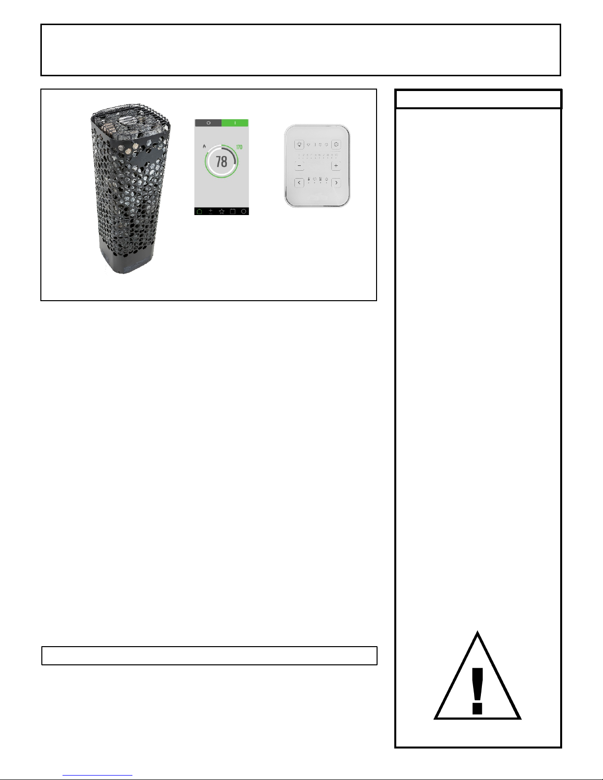
Premium
Control
1601-33 or
1601-33-1
Trend
Control
1601-31 or
1601-31-1
Himalaya “Premium" Series Sauna Heaters
Models 7.0, 9.0
(Type #'s 1118-702-1707, 1118-902-1707)
with Premium Control (Type # 1601-33 and 1601-33-1)
And/Or Trend Control (Type # 1601-31 and 1601-31-1).
Page 1
WARNING
Do not take a sauna if using
alcohol, drugs or
medications.
Pregnant women or persons
with poor health should
consult their physician before
using any sauna.
Caution re hazard: Do not
use the sauna room for
drying clothes, bathing suits,
etc. Do not hang towels
above heater or place any
object other than the rocks
supplied on the heater. If any
darkening of the wall around
the heater is noticed
discontinue sauna use
immediately.
Read all instructions carefully before installation. Please leave all
instructions and warranty with the owner.
WARNING
Prolonged exposure to elevated temperatures is capable of inducing
hyperthermia. Hyperthermia occurs when the internal temperature of the
body reaches several degrees above the normal body temperature of
98.6°F. The symptoms of hyperthermia include an increase in the normal
temperature of the body, dizziness, lethargy, drowsiness, and fainting. The
effects of the hyperthermia include failure to perceive heat, failure to
recognize the need to exit the room, unawareness of impending hazard,
fetal damage in pregnant women, physical inability to exit the room and
unconsciousness.
WARNING
The use of alcohol, drugs, or medication is capable of greatly increasing
the risk of fatal hyperthermia.
SECTION 1: GENERAL INFORMATION
These heaters are ETL approved by Intertek for permanent installations and
electrical connections. Built with splash proof construction, the conducting
parts are protected against water. All wiring must be performed in
accordance with national and local codes. See Diagram 2 for wire and
room size requirements. These heaters are oor mounted.
Inspect sauna regularly for
required maintenance to
heater, control and benches.
Replace wood surfaces
which show any signs of
deterioration.
The heater gets extremely hot
during operation and should
not be touched or burns may
result.
Minors should be adequately
supervised whenever near a
hot or warming sauna.
72-0112 03-06-18 7013500 314 SKLT 69 A
INSTALLATION AND OPERATING INSTRUCTIONS
WIRE SIZE
Floor
Area
Wall
Height
Volume
Cu.Ft.
Wall
Height
Volume
Cu.Ft.
Power Supply to
Heater
1 208 32.7 2 #8AWG+N+GR
1 240 28.3 2 #8AWG+N+GR
3 208 18.9 3 #10AWG+N+GR
3 240 16.4 3 #10AWG+N+GR
1 208 43.3 2 #6AWG+N+GR
1 240 37.5 2 #6AWG+N+GR
3 208 25.0 3 #8AWG+N+GR
3 240 21.7 3 #10AWG+N+GR
350
Himalaya Trend 9.0
1118-902-1707
9.0 38 sq. ft. 75" 310 96" 500
Himalaya Trend 7.0
1118-702-1707
6.8 21 sq. ft. 75" 175 96"
AMPS
HEATER MODEL /
Product Number KW
MINIMUM ROOM MAXIMUM ROOM
PHASE VAC
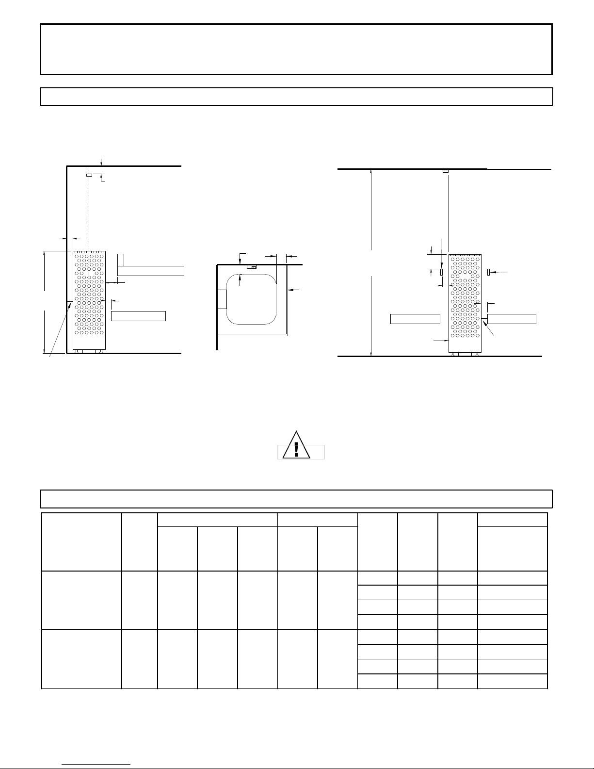
DIAGRAM 1
MOUNTING BRACKET LOCATION AND MINIMUM DISTANCE TO COMBUSTIBLE MATERIAL
Page 2
3"
1/2
2 "
Upper Bench
5"
1/2
41"
Heater Wall
Support
Side View of
2 "
Lower Bench
Corner Installation
Recheck your distances from the heater to
combustible materials to be sure you have
the proper minimum distances.
All dimensions are
minimum distances
except sensor.
1/2
2 "
Top View of
Corner Installation
Heater
Guard
1/2
2 "
75"
Heater
Guard
Lower Bench
6"
1/2
2 "
High Limit
Reset
Side View of Middle Room
Installation
OBSERVING MINIMUM DISTANCES IS
REQUIRED TO REDUCE THE RISK OF FIRE
Heater
Guard
1/2
2 "
Lower Bench
Heater Bench
Support
NOTE 1: Neutral is required for heater and control to operate. Light output from heater is 120 volts at 2 amps maximum.
72-0112 03-06-18 7013500 314 SKLT 69 A
DIAGRAM 2
INSTALLATION AND OPERATING INSTRUCTIONS
Page 3
SECTION 2: MOUNTING OF SAUNA HEATER
-NOTE: Complete electrical connections and test the heater prior to this step.
Attach wall bracket to any of the mounting holes located on either side of the spine on the
rear of the heater shroud (reference diagram 4). Slide heater into position, according to
dimensions shown in Diagram 1 and mark locations for the two mounting screws. Slide
heater forward and screw two 1/4” x 1” lag bolts into sauna wall at locations marked
earlier, leaving approximately 1/8” of bolt shoulder exposed so bracket can easily slide over
bolt heads. Re-locate heater into position with key-holes of bracket locking onto lag bolts.
Adjust the leveling feet to ensure that the heater is vertical. Use a level on two sides of
heater to verify plumb.
If mounting heater in center of room, use same procedure described above but locate
mounting bracket so that it can attach to the bench framing that surrounds the heater.
SECTION 3: PLACING OF ROCKS (SEE DIAGRAMS #10 and 11)
The rocks supplied have been chosen to provide the best heater performance. Use of any
other type of rock may void the heaters warranty. Never operate the heater without rocks
in place! Rinse the rocks with water before placing in the heater.
Install the BWT (Bio Water Technique) tank between the second and third heating
elements resting on the top of the elements. (See diagram 11) The BWT tank has slots in
the outer ange that will align with the element loops. Install the BWT cover and the round
herb cup.
Start inserting rocks into the heater in even layers so that the 3 heating elements remain
as vertical and evenly spaced as possible. Continue to randomly drop rocks into the
heater until you are even with the top of the heating coils. Add one more loose layer to
cover up the elements and top of the BWT. (Do Not Cover Up the round herb cub on top
of the BWT!) The rocks must fully cover the heating elements. Attach the guard with the
screws provided. See Diagram #10 & 11 for rock placement.
Packing the rocks too tightly may cause the heater high limit switch to trip.
SECTION 4: ELECTRICAL HOOK-UP
Electrical installation must be made by a licensed electrician in accordance with the
National Electrical Code and local regulations.
- NOTE: A GFCI (Ground Fault Circuit Interrupt) device is not required by ETL. A GFCI may
be installed if required by local codes but will nuisance trip during use of the product. CAUTION: Loose wire connections can cause heat damage to wires, terminal blocks and
other components and may void the warranty.
Remove the screws from the left and right sides of the electrical box. Remove the painted
trim piece from the front of the box. Route the feed wires through the holes provided in the
bottom of the heater and connect the wires to the terminal block. To determine the correct
wire size, refer to Diagram 2. Use copper supply wire only, suitable for minimum 90
degrees C. The heater must be grounded! See Diagram 6 for proper connections.
SECTION 5: TEMPERATURE SENSOR
Feed the "low voltage" sensor wire from the sensor to the sauna heater location. Sensor
wire must be routed completely separate (as per low voltage electrical wiring codes) from
any wiring carrying over 50 volts. It may be necessary to drill holes to string the wire
through the studs or ceiling joists. Route the wire to bottom of the heater and connect to
the sensor connection. Mount sensor to nished wall 3" from the ceiling directly above
the heater using two (2) screws (provided) as shown in diagrams 1, 3 & 5.
WARNING
Fire sprinkler systems used
inside any sauna room should
be properly rated for sauna
room temperatures.
Do not place hands
and or arms over the BWT
when hot. Steam from BWT
may cause severe burns.
Do not pour chlorinated pool
or spa water on heater or in
the BWT.
Excessive water use on heater
may cause damage and void
warranty.
Electric Shock Hazard - High
voltage exists within this
equipment. There are no user
serviceable parts in this
equipment. All installation
and service to this equipment
should be performed by
qualied licensed personnel
in accordance with local and
national codes.
Do not construct sauna room
so as to restrict air ow
through the bottom of the
heater.
Packing the rocks too tightly
may cause the heater high
limit switch to trip.
If mounting heater in the middle of your sauna room, locate the temperature sensor on the
ceiling above the heater at a point directly above one outer edge of the sauna heater
shroud. See Diagram 1.
72-0112 03-06-18 7013500 314 SKLT 69 A
INSTALLATION AND OPERATING INSTRUCTIONS
Page 4
Sensor
Wire
Trend
Control
Minimum
ceiling
spacing
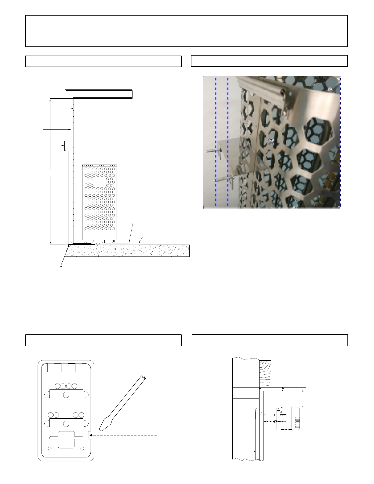
DIAGRAM 3
Se n s or protec t i ve cover. L ocate bot t o m
of s e nsor hori z o ntally 3" f r om ceilin g
an d d irectly a b o ve the hea t e r.
75"
He a ter Inpu t Pow e r
DIAGRAM 4
Bracket ts in any hexagon opening and then screws
Light Output Power
to the wall or bench.
1 5 fo o t L o w Vo lt ag e C ab le pr ov i de d w it h c on t ro l.
DIAGRAM 5
Back of
sensor
Insert screwdriver tip here to unsnap
sensor cover from sensor.
Note vertical orientation of cover
before removing.
DIAGRAM 5, continued
3" from ceiling to
top of sensor and
centered above
the heater.
72-0112 03-06-18 7013500 314 SKLT 69 A
INSTALLATION AND OPERATING INSTRUCTIONS
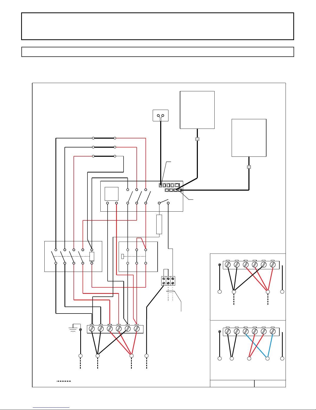
DIAGRAM 6
Single Phase Wiring Diagram Color Code
Himalaya Heater Models
1118-702-1707 6.8 kW
1118-902-1707 9.0 kW
Front
Element
Sensor
2 3
Premium
Control
1601-33 or
1601-33-1
Page 5
Trend
Control
4
2
Contactor
1 3
6 8 A2
5 7
A1
1 2 3
Middle
Element
Back
Element
Transformer
X1 X2 X3
X4
P1 P2 P3
1 2 3
4 5
X6 X8
X5 X7
6
X13 X14
2 Amp
Breaker
Switch
High Limit
N
120 Volt Light Output
2.0 Amp Max
Sensor
H
4 Control Ports
GND
Single Phase Connections
1
L1
1
1601-31 or
1601-31-1
2 3
2 3
4 5
L2
4 5
6
N
6
GND
L1
Single Phase Connections
Field Wiring
72-0112 03-06-18 7013500 314 SKLT 69 A
L2
N
GND
L1
L2 L3
N
Three Phase Connections
354 SKLT 19 A
02/21/18
INSTALLATION AND OPERATING INSTRUCTIONS
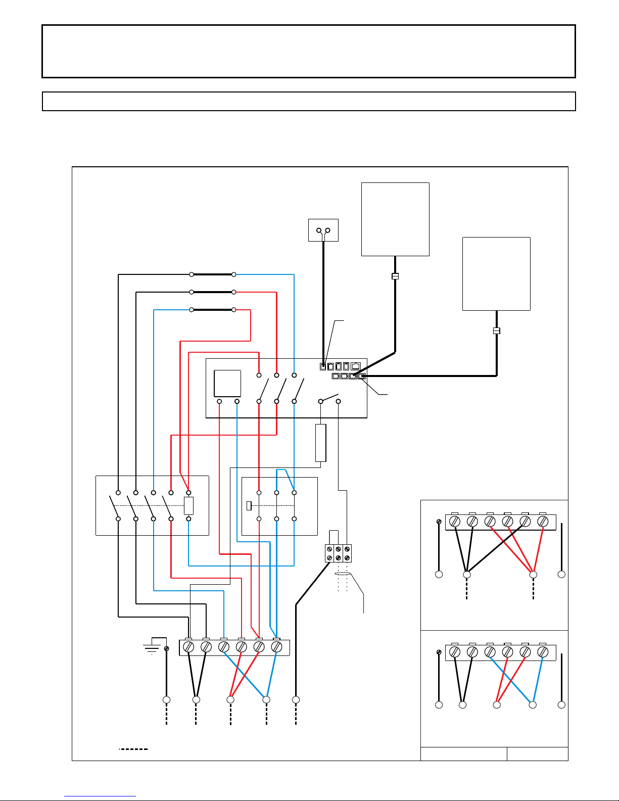
DIAGRAM 6
Three Phase Wiring Diagram Color Code
Himalaya Heater Models
1118-702-1707 6.8 kW
1118-902-1707 9.0 kW
Front
Element
Sensor
2 3
Premium
Control
1601-33 or
1601-33-1
Page 6
Trend
Control
4
2
Contactor
1 3
6 8 A2
5 7
A1
1 2 3
Middle
Element
Back
Element
Transformer
X1 X2 X3
P1 P2 P3
1 2 3
4 5
X4
X6 X8
X5 X7
6
2 Amp
Breaker
Switch
High Limit
N
120 Volt Light Output
2.0 Amp Max
Sensor
H
4 Control Ports
GND
Single Phase Connections
1
L1
1
1601-31 or
1601-31-1
2 3
2 3
4 5
L2
4 5
6
N
6
GND
L1
Three Phase Connections
Field Wiring
72-0112 03-06-18 7013500 314 SKLT 69 A
L2
L3
N
GND
L1
L2 L3
N
Three Phase Connections
354 SKLT 19 A
02/21/18
INSTALLATION AND OPERATING INSTRUCTIONS
Page 7
SECTION 6: HEATER GUARD RAIL
Install a wooden heater guard to prevent the sauna bather from accidentally
touching the sauna heater. Install the heater guard rail with the dimensions shown
in Diagram 1.
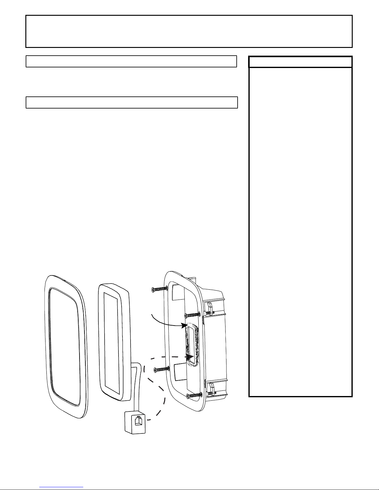
SECTION 7: CONTROL INSTALLATION & OPERATION
INSTALLATION ROUGH IN: Place the control inside or outside the sauna room. If
the control is installed inside a sauna room, the top of the unit cannot be higher
than 48 inches above oor. Maximum control cable length is 50 feet.
String the provided low voltage control cable through 1” holes in the wall studs or
ceiling joists from the control location to the heater. Do not use staples to secure
the low voltage cable, it may damage the cable!
Plug the control cable into the control and TEST the control BEFORE mounting!!
After testing is complete, CLEAN the mounting surface to ensure it is free from
dust. Remove the adhesive tape from the back of the control, push any excess
cable into wall cavity and press the control to the mounting surface.
CONTROL OPTIONS: This heater has two different control options. A Premium
Control (1601-33 or 1601-33-1) or Trend Control (1601-31 or 1601-31-1) can
be connected to the heater. This heater can suppor t both at the same time as
another option.
WARNING
Do not locate benches over
heater. Refer to Diagram 1
for minimum clearance of
ceiling above heater is
required.
Minimum clearance from
heater to wooden surfaces
(benches, side walls, heater
fence etc.) is required. Refer
to Diagram 1 for specic
information.
Mounting brackets supplied.
Provides proper clearance
from wall behind heater.
Use only copper wire of the
size and type indicated in the
Heater Specication Chart
and the temperature rating
indicated on the heater
junction box.
All heaters and controls must
be grounded per NEC to
prevent electrical shock in
case of unit failure.
Electrical outlets or
receptacle must not be
installed in a sauna room.
A guardrail or fence is
required around the heater to
prevent burns from
accidental contact.
72-0112 03-06-18 7013500 314 SKLT 69 A
 Loading...