

Hiltron DC28, TDC36, ERMES2, TM26GSM, TM66GSM User Manual

GSM phone dialers
with vocal messages
TDC28 - TDC36 - TM26GSM
TM66GSM - ERMES2
USER’S MANUAL
(for circuits 622aMA-2 and ).xx 711aMA-1.xx
ITALIANO
ENGLISH

TDC28 -TDC36-TM26GSM-TM66GSM-ERMES2
User’s manual
2 3
Index
Chapter 1 - Introduction ....................................................................3
1.1 Functional characteristics .................................................................................3
1.2 Technical characteristics ..................................................................................3
Chapter 2 - Installation ......................................................................4
2.1 Connections TDC28.........................................................................................4
2.2 Connections ERMES2-TM66GSM-TM26GSM-TDC36.................................... 5
Chapter 3 - Programmation...............................................................6
3.1 Accessing programming.................................................................................. 7
3.2 Address book...................................................................................................8
3.3 Vocal messages.............................................................................................10
3.4 TXT/SMS messages......................................................................................12
3.5 Channels........................................................................................................14
3.6 Output............................................................................................................ 16
3.6.1 Mode................................................................................................. 17
3.6.2 Reference input.................................................................................17
3.6.3 Pulse duration................................................................................... 18
3.7 Parameters.................................................................................................... 18
3.7.1 Remote control..................................................................................19
3.7.2 Language selection........................................................................... 19
3.7.3 Reply pulse....................................................................................... 20
3.7.4 Numbers of calls................................................................................20
3.7.5 Numbers of messages... ...................................................................21
3.7.6 Beep no Registr................................................................................. 21
3.8 Codes.............................................................................................................21
3.9 Info................................................................................................................. 23
3.10 Reset default settings................................................................................... 23
Chapter 4 - Operation............................................................................24
4.1 General description of operation................................................................... 24
4.2 Local control.................................................................................................. 25
4.2.1 Stop cycle..........................................................................................25
4.2.2 Stop all cycles....................................................................................25
4.2.3 Output command...............................................................................26
4.2.4 Input status........................................................................................27
4.2.5 Out of order....................................................................................... 27
4.2.6 In service...........................................................................................28
4.2.7 Telephone......................................................................................... 28
4.2.8 Remote control..................................................................................29
1 Introduction
1.1 Functional characteristics
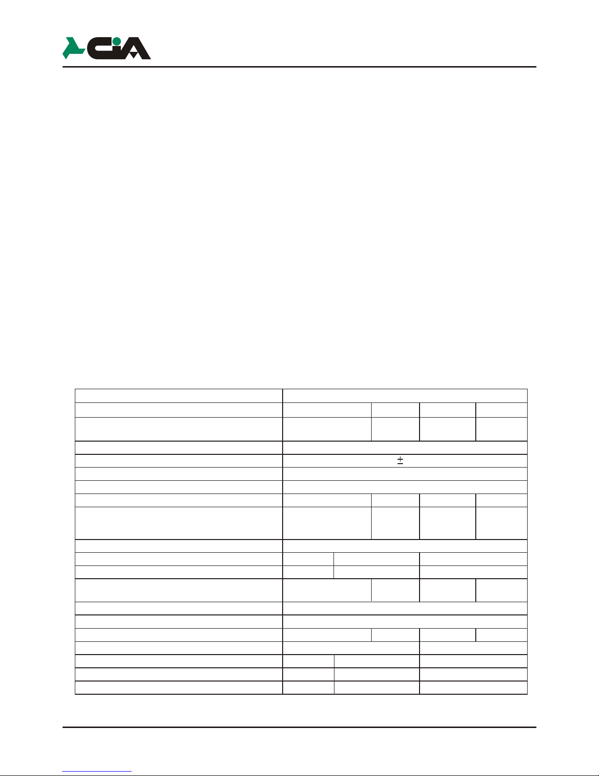
1.2 Technical characteristics
! Built-in microphone
! Dual Band GSM module
! Delay on input singularly programmable
! Possibility to assign each phone number singularly to one channel, some
! Antiopening and antitearing protection tamper
! Multiple languages: Italian, English, French, German, Spanish, Portuguese
! Indication of the intensity of GSM signal and of the telephone manager
! Message repetitions and calling cycles settable
! 'Out of order' function
! CLIP function :One output control by one ring (call without answer) from one
Introduction
1 Introduction
1.1 Functional characteristics
1.2 Technical characteristics
! Built-in microphone
! Dual Band GSM module
! Delay on input singularly programmable
! Possibility to assign each phone number singularly to one channel, some
channel or to all channels
! Antiopening and antitearing protection tamper
! Multiple languages: Italian, English, French, German, Spanish, Portuguese
! Indication of the intensity of GSM signal and of the telephone manager
! Message repetitions and calling cycles settable
! 'Out of order' function
! CLIP function :One output control by one ring (call without answer) from one
phone number in SMS address book, with automatic return of confirming ring
TDC36 TM26GSMERMES2TDC28
TM66GSM
Remote ambient listening
SMS messages (128 car.) activation each channel
Short texts (16 chars) for viewing
the State of the inputs and outputs
Operators codes settable
Power supply voltage
Max. current consumption
Consumption in st/by
Vocal messages (16 sec.)
State vocal messages (2sec.) for input/outputs
state monitoring
Address book
Bay for battery
Power supply / power set
Input channels programmable as pulse or status
mode, conditionable to the others
Input channels conditioning INT
Programmable relay outputs
100mA open collector programmable outputs
External box
Dimensions (W)
Dimensions (H)
Dimensions(D)
2 6 2 6
12 28 12 28
MASTER and COMMANDOS code
12Vdc 10%
400mA
70mA
3 7 3 7
12 28 12 28
16 numbers
12V7Ah (non incl.)
AL1 (included)
2 6 2 6
2
1
1
5 1
5
ABS
metal
140mm
115mm
29mm
280mm
230mm
96mm
285mm
95mm
17mm

4
2 Installation
2.1 Connections TDC28
V R
C NC NA
Uscita
LED
Relay 2
(optionally)
Electronic key
Proximity key
Burglar
central unit
Sir
12Vcc12V int
Chiave
TDC28
GND
in
-
GND
IN
K2
INT
2
TAMPER
INT
1
IN
K1
GND
in
-
GND
C
+ 12V -
NANC
OUT1
OUT
2
1.Important:
Use any GSM phone for
delete the access code (PIN code)
that enables the use of the SIM CARD.
To insert or remove the terminal blocks
perform the operation as shown in figures
2. Insert the SIM card inside the module taking into account
the beveled corner.
3.NOT FORCING THE SIM.
Insert with sweetness the male connector of the antenna
on the phone dialer as shown in the figure.
V R
C NC NA
Uscita
LED
Electronic key
Proximity key
GND
in
-
GND
C
+ 12V -
NANC
OUT1
OUT
2
1.Important:
Use any GSM phone for
delete the access code (PIN code)
that enables the use of the SIM CARD.
The base of TDC28 can be mounted on a
standard wall-mounted box “503” type.
For the antitheft protection, fixing
with the screw in dotation
ERMES2
TM66GSM
TDC36
TM26GSM
Burglar
central unit
Installation
IN4
IN5
IN6
only
for ERMES2
OUT3
OUT4
OUT5
OUT6
only
in the ERMES2
and TDC36
230V~
50Hz
Switch
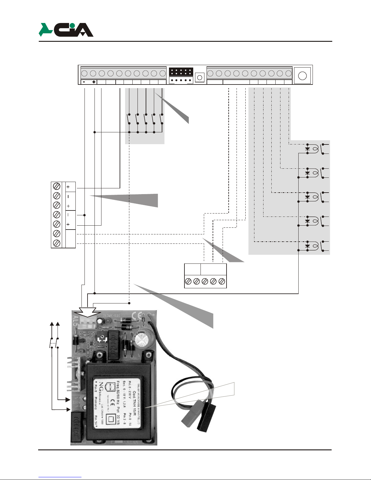
2.2 Connections ERMES2 / TM66GSM / TDC36 / TM26GSM
Installation
IN3
IN4
IN5
IN6
only
for ERMES2
OUT3
OUT4
OUT5
OUT6
for ERMES2
SETUP
K4K6K5
C1 NC1NA1
Tamper
U4
U6
U2 U3
U5
OUT2
This connection allows the input and
output of the burglar alarm whether
with the electronic key as
with phone dial.
NOTE: If you use only the phone dial
is necessary to connect only the
output C and NC of the Relay1 of the
phone dial on Key terminals of the
central unit.
TDC28 -TDC36-TM26GSM-TM66GSM-ERMES2
User’s manual
Installation
5
Installation
ERMES2
TM66GSM
TDC36
TM26GSM
Burglar
central unit
IN2
IN3
IN4
IN5
IN6
IN1
Black
Red
White
INT1
only
for ERMES2
OUT3
OUT4
OUT5
OUT6
for ERMES2
and TM66GSM
only
in the ERMES2
and TDC36
Installation
IN4
IN5
IN6
only
for ERMES2
OUT3
OUT4
OUT5
OUT6
only
in the ERMES2
and TDC36
Net
230V~
50Hz
Switch
Int1 K1Int2
12V
SETUP
K4
K6
K2 K3
K5
C1 NC1NA1
Tamper
U4
U6
U2 U3
U5
OUT2
2.2 Connections ERMES2 / TM66GSM / TDC36 / TM26GSM
Chiave
12V int
12Vcc
Sir
Installation
IN3
IN4
IN5
IN6
only
for ERMES2
OUT3
OUT4
OUT5
OUT6
for ERMES2
SETUP
K4K6K5
C1 NC1NA1
Tamper
U4
U6
U2 U3
U5
OUT2
V R
NA NC C
Uscita
LED
Electronic Key/
Proximity Key
Channel 2÷6
activation
example
OUT1
ATTENTION!
In order to use the
positive outputs ‘+ Sir’ e ‘+ Int.’
Of burglar central the negative
must be in common
to the feeding of
ERMES2 / TM66GSM
This connection allows
the insertion and the not
insertion at a distance of
burglar central unit united to
uses of electronic key.
This connection, if used, consents
to send to one of inputs (K1,K2...) A positive one
of reference in presence of main voltage 230 Vac.
Setting up in the programming the input like
“Positive Level”, to lacking the mains voltage
telephone dialer will send the message of relative alarm.
6 7
CH2 DisabledDD
25Y ABCDA
25Y ABCDA
3 Programmation
After the installation and the power to the telephone dialer select your language
using the keys and confirm with or .
The disponible language :
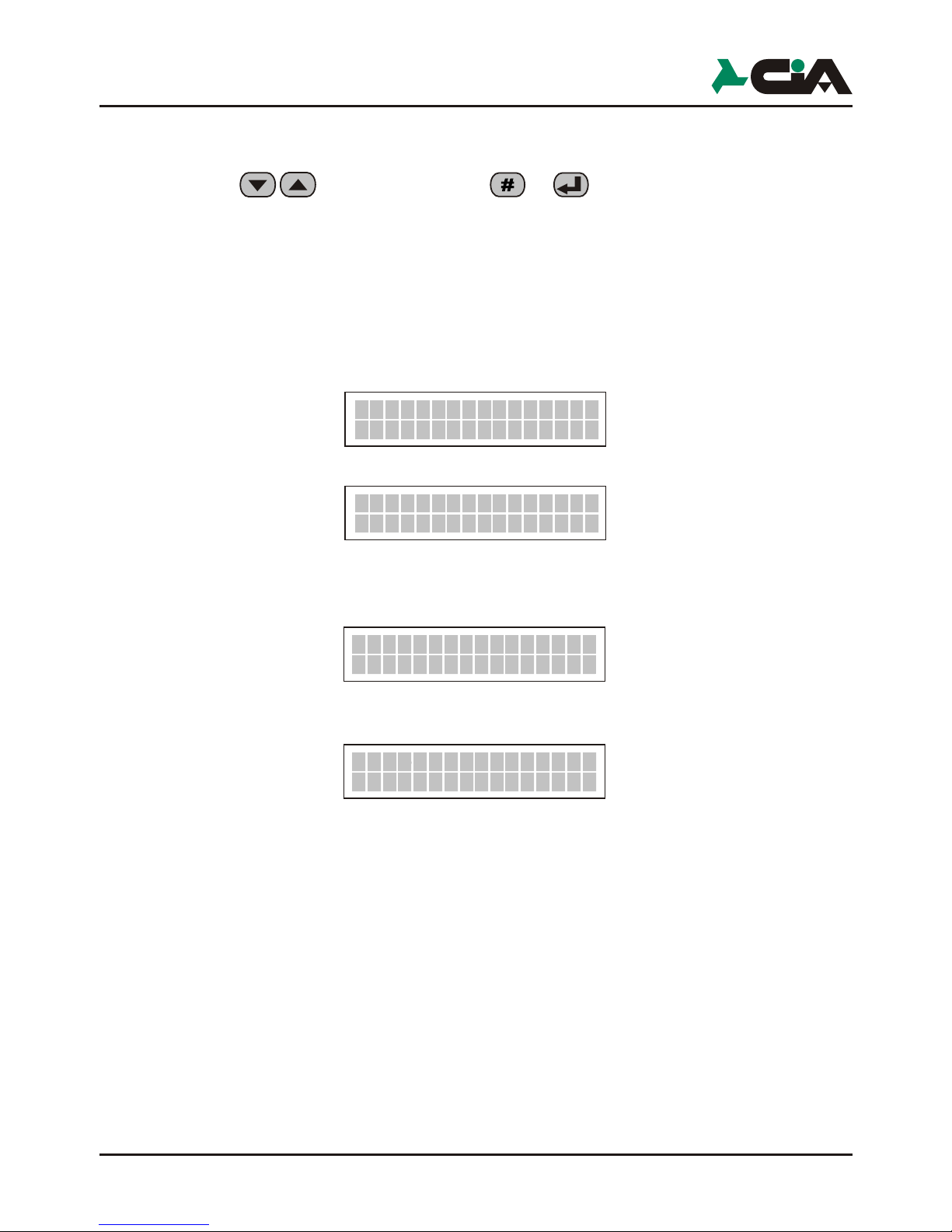
After selecting language, the telephone dialer, is able to stand/by show status,
rolling, the two input channels (default CH1 and CH2 is enabled is disabled).
This will be displayed:
which alternates with:
After inserting the SIM the telephone dialer will register to the network of the
provider, you displayed :
When is effected the registration, is displayed :
NOTE :
To activate a series of calls on a channel you must have enabled at least one
phone number: "Ch1 Heading OFF" indicates that the channel 1 is not associated
with any telephone number or for voice calls, nor for sending SMS and result notoperative.
Italian, English, French, Spanish, Portugues,
German.
To operate in the various menu you can use the keys until you see, for
example:
and confirm with or
or use the shortcut key (for example Programmation).
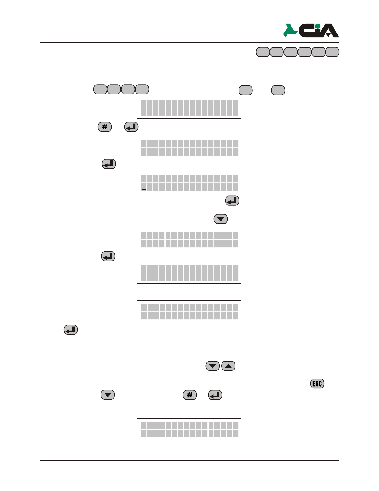
3.1 Accessing programming
The programmation of the telephone dialer is allowed only with local keyboard, digit
the MASTER code ( )
Digit the code (MASTER code default)
Press the key (Programmation)
The programmation of the telephone dialer includes:
1 - Address Book 16 address book numbers, that will be sent Vocal Messages
3 - Vocal Mess. 3 from 12 sec. (Common message, Channel 1, Channel 2)
4 - Text/SMS Mess. IN and OUT description of channels and of other inputs and
5 - Channels Impostation of the input, setting conditions and delays in
6 - Output Impostation of the outputs.
7 - Parameters In this section are given in the operating parameters of the
8 - Codes Variation of MASTER Code and of COMMANDS code.
0 - Info Visualization info the dialer model and of the firmware.
This applies both in the Main Menu to access a submenu, either within the various
submenus, where you can also use key shortcuts to select a particular parameter,
a given plant, and so on.
Is possible anyway abandon the programmation with press the key or
10YOABCD
Registration...
TDC28 -TDC36-TM26GSM-TM66GSM-ERMES2
User’s manual
Ch1 OffRubric
Ch1 OffRubric
Ch1 OffRubric
Ch1 OffRubric
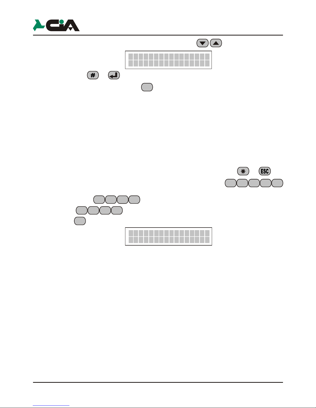
To operate in the various menu you can use the keys until you see, for
example:
and confirm with or
or use the shortcut key (for example Programmation).
NOTE In the manual, in most cases, you will use the mode with the
keyboard shortcuts. Thus, while consulting the manual, you can
use the sequence of the key for each Paragraph next to quickly
access the programming described in it.
3.1 Accessing programming
The programmation of the telephone dialer is allowed only with local keyboard, digit
the MASTER code ( )
Digit the code (MASTER code default)
Press the key (Programmation)
The programmation of the telephone dialer includes:
1 - Address Book 16 address book numbers, that will be sent Vocal Messages
3 - Vocal Mess. 3 from 12 sec. (Common message, Channel 1, Channel 2)
+ 12 status messages of 2sec. seconds each for the TDC28
and TM26GSM.
7 from 12 sec. + 28 status messages for ERMES2 and
TM66GSM
4 - Text/SMS Mess. IN and OUT description of channels and of other inputs and
outputs (mess. max of 128 characters for CH1 and CH2; 16
for all other K1, K2,I NT1, INT2,OUT1 e OUT2).
5 - Channels Impostation of the input, setting conditions and delays in
activation.
6 - Output Impostation of the outputs.
7 - Parameters In this section are given in the operating parameters of the
telephone dialer.
8 - Codes Variation of MASTER Code and of COMMANDS code.
0 - Info Visualization info the dialer model and of the firmware.
This applies both in the Main Menu to access a submenu, either within the various
submenus, where you can also use key shortcuts to select a particular parameter,
a given plant, and so on.
Is possible anyway abandon the programmation with press the key or
PROGRAMMING
1-Rubric
6
5
7
8 8
6
5
7
8
8
6
5
7
8
Programmation
8-PROGRAMMATION
Init GSMo
8
8
Num.001
Number00001
6
5
7
8 8
1
6
5
7
8
8
3.2 Address Book
In this menu you can enter or edit the phone numbers that the controller should
call in case of activation of a channel.
Digit the code and press in sequence and is displayed
digit one button or :
Press the button
Digit the number that you want to store, and press .
When you have stored the phone number, digit :
Press the button
Digit a name to memorized (for example) :
Press for memorize.
NOTE: The maximum length of the name to be inserted is 16 characters.
NOTE: For delete or change a character, use . The same applies to
select and type the new character.
Press the button and confirm with or is displayed :
Num.001
Name
NotoProgrammed
Number
1
Number
0000000000000>
Num.00100000000>
Name
MisteroRED
2-Name
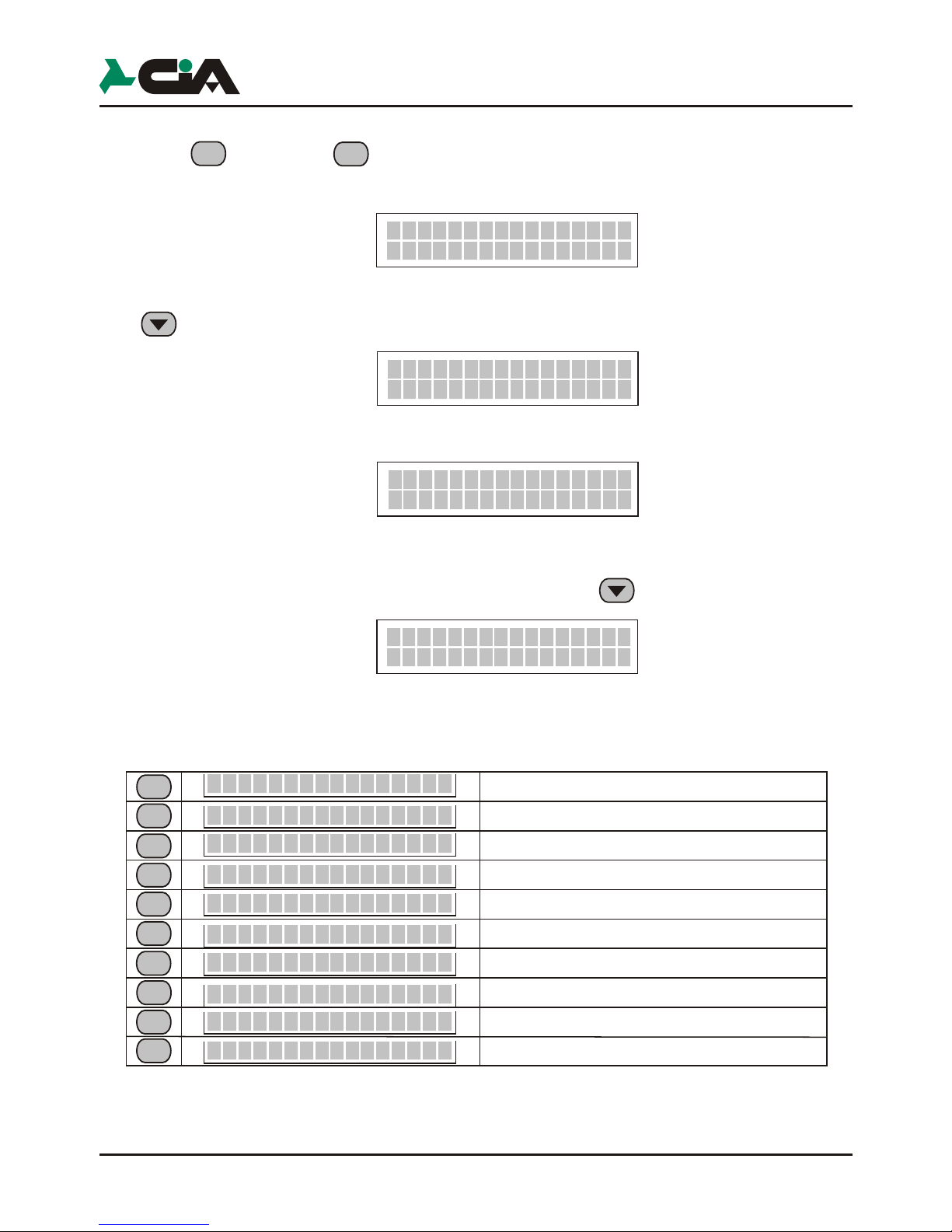
Vocal
Channel >--oooooo
For bind a channel to the number, press the key that corresponds to the channel
(example channel 1; for channel 2, etc.). To delete the assignment simply
retype the channel number is displayed:
Once you have assigned one or more channels in the phone number box, type the
key is displayed:
Press the corresponding button for the channel to which you want to assign the
sms.
Once you have assigned one or more channels, press is displayed:
In this menu item you can place the operation which the controller performs when
receives a call from the number recorded in the address book.
TDC28 -TDC36-TM26GSM-TM66GSM-ERMES2
User’s manual
call
9
Programmation
For bind a channel to the number, press the key that corresponds to the channel
(example channel 1; for channel 2, etc.). To delete the assignment simply
retype the channel number is displayed:
Once you have assigned one or more channels in the phone number box, type the
key is displayed:
Press the corresponding button for the channel to which you want to assign the
sms.
Once you have assigned one or more channels, press is displayed:
In this menu item you can place the operation which the controller performs when
receives a call from the number recorded in the address book.
2
SMS
Channel >--oooooo
SMS
Channel >1-oooooo
1
Clip
--Off
Channel >1-oooooo
1
2
3
4
5
6
7
8
9
OUT1oOFF --
OUT2oOFF -OUT3oOFF --
OUT4oOFF -OUT5oOFF --
OUT6oOFF -OUTXoON --
OUTXoOFF CR
--
0
OFF
OUTXoOFF
Select the output 1
Select the output 2
Select the output 3
Select the output 4
Select the output 5
Select the output 6
Prepares a command ON the output slected
Enable the confirmation call
Disabled the CLIP
Prepares a command OFF the output slected
Vocal call
*
#oRec
6
5
7
8 8
3
6
5
7
8
3
8
>>>>>>>>>>>>>>>>
>>>>>>>>>>>>>>>>
Msg. COMUNE
Canale 1
Canale 2
Indication on the first line of the display
Alarm
messages
Duration:
Utilize:
16 sec.
16 sec.
16 sec.
It is broadcast for first during
a call alarm loop
Follows the common message
When you enable channel 1
Follows the common message
When you enable channel 2
8
25YoABCD
CH1
Completed the setting to the number entered, press the button once to go
back and select the next number to be stored using the keys.
Repeat the same procedure for the other numbers.
NOTE: If no number is entered in the address book and assigned to one of the
channels enabled, the telephone dialer is displayed:
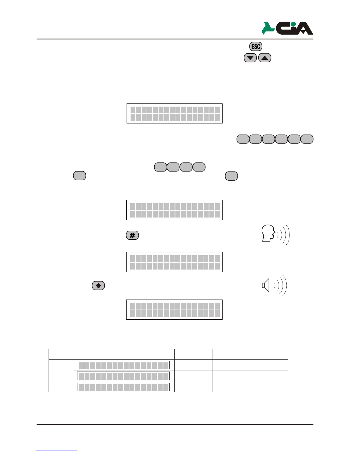
3.3 Vocal Mess.
The vocal messages are those that the dialer uses to signal an alarm or the status
of the inputs and outputs the user during a dial-up connection.
Enter the default Code (MASTER),
then press (Vocal Messages) and finally the button . Is displayed:
Press and hold the button (registration) and say the message
you show :
Press the button (playback) for listen the messages
is displayed :
The following table lists the available voice messages:
NOTE: The channels displayed for models ERMES2, TM66GSM are 6
Play
The message sent during a call as a result of the activation of a channel is
composed of the common message followed by specific message channel
enabled, all repeated for as many times as indicated by the "Num" parameter
(see section 3.7.5).
The status messages are used during remote control to indicate the status of the
inputs and outputs and are transmitted as a result of an activation command
or query outputs, or as a result of a query command inputs.
NOTE: In ERMES2 and TM66GSM models, voice messages are a total of 12
Once registered, select the next voice message to be stored using the keys
and then press the button and repeat the same procedure above to
store just the other messages.
The following table lists the available status messages:
TDC28 -TDC36-TM26GSM-TM66GSM-ERMES2
User’s manual
Rubric Off
COMMON
Msg.
COMMON
Msg.
COMMON
Msg.
 Loading...