

Hiltron H347B User Manual
USER'S MANUAL
ENGLISH
H347B
5 zones burglar central unit

Contents
Chapter 1 Introduction 4
1.1 Central Unit Description ...........................................................................................4
1.2 Operating Features ..................................................................................................4
1.3 Technical Features...................................................................................................5
Chapter 2 Installation 6
2.1 General Instructions.................................................................................................6
2.2 “Radiophonic Listening” function..............................................................................6
2.3 Power Supply...........................................................................................................7
2.4 System Configuration and Wiring ............................................................................8
2.4.1 Zone 1 (wired) ............................................................................................8
2.4.2 Telephone Dialer ........................................................................................9
2.4.3 Additional Sirens ........................................................................................9
Chapter 3 Programming Procedures 10
3.1 Initial Setup ...........................................................................................................10
3.1.1 RF Channel Test.......................................................................................11
3.1.1.1 “Radiophonic Listening” function .......................................................11
3.1.1.2 350B Siren Control ............................................................................11
3.1.2 Times Regulation......................................................................................12
3.1.2.1 Exiting Time Regulation.....................................................................12
3.1.2.2 Entering Time Regulation ..................................................................12
3.1.2.3 Alarm Time Regulation ......................................................................12
3.1.3 Settings ....................................................................................................13
3.1.3.1 Entering/Exiting Acoustic Signalling ..................................................13
3.1.3.2 Main Power Supply Absence Alarm on Disabled System..................13
3.1.3.3 RF Channel Sabotage Acoustic Signalling ........................................13
3.1.3.4 Acoustic Signalling in case of Main Power Supply Absence and
Anomaly of Power Suppliers, on desabled system .............................................................14
3.1.4 System Code............................................................................................15
3.1.4.1 System Code Entering.......................................................................15
3.1.4.2 System Code Display ........................................................................16
3.1.5 End of Programming Procedures .............................................................17
3.1.5.1 Default Settings Reset.......................................................................17
3.1.5.2 Exiting Without Savings.....................................................................17
3.1.5.3 Changes Confirmation.......................................................................17
3.2 345B Remote-control Programming ......................................................................18
Chapter 4 Operating Procedures 19
4.1 Front Panel 19
4.2 Enabling / Desabling System .................................................................................20
Chapter 5 Maintenance 24
2 3

4.2.1 Enabling System ......................................................................................20
4.2.2 Desabling System ....................................................................................20
4.2.3 Optional Command Systems....................................................................20
4.3 Zones Exclusion.....................................................................................................21
4.4 Zones Operating ....................................................................................................21
4.4.1 Zone 1 wired (delayed/immediate) ...........................................................21
4.4.2 Zones 2 / 3 / 4 (immediates).....................................................................21
4.5 Alarm Memory........................................................................................................23
4.6 Acoustic Signallings ...............................................................................................23
Chapter 5 Maintenance 24
5.1 Replacing of the parts ............................................................................................24
5.2 Cleaning.................................................................................................................24
5.3 Fuses ... .................................................................................................................24
ContentsH347B - User’s Manual

! Central Unit protection by internal tamper (can be excluded for maintenance).
1.3 Technical Features
! Maximum current supplied in services output: 400mA
! Maximum current supplied by power supplier: 700mA
! Fuse on services output voltage: 1A type F
! Box : ABS.
! Operating Voltage: 230Vac ±10% 50Hz
! Maximum absorption: 80mA
! Transformer fuse: (primary) 250mA type F
! : (secondary) 1A type F
! Buffer battery: 12V 7Ah
! Service output voltage: 13Vdc ±5%
! Sirens Output Fuse: 3,15 A F
! Minimum Operating Temperature: 5°C ±2%
! 40°C ±2%
! Box Protection Level: IP30
! Dimensions: 280x230x95mm
1 Introduction
Dear Customer,
Thanks to have bought a HILTRON product. Please read this manual thoroughly before
use and during the installation. Keep it handy for future reference.
As HILTRON customer, you can
HILTRON
1.1 Central Unit Description
The H347B is a burglar central unit with microprocessor technology for Burglar Protection
System , all and medium private and commercial premises. It allows to manage a wired
zone by traditional NC line, and also to manage three radio zones where you can connect
unlimited number of volumetric detectors typ 348B 346B
350B
manage the remote of H295G sirens and
telephone dialers by relay.
173C, H287B or H105B.
1.2 Operating Features
!
!
!
!
!
!
use a series of services, such as the telephone technical
assistance on the products.
to use also with "switch" fast contacts.
Alarm is signalled by the self-powered radio electronic siren H ; moreover, other
additional signalling are realizable by wired connection (of a siren type H295G, H125H or a
telephone dialer) directly to the central unit, or by H353B radio module, which signals the alarm
status of the system, and to allow to enabling
has to use
"24h"
enabled/disabled system, alarm, unloaded
batteries and sirens voltage with acoustic signalling (excludible), RX/TX
(excludible)
(excludible)
excludible
! Automatic alarm occurs in case of main power supply absence.(programmable)
! Enabling/desabling system by remote control H345B, mechanic key on front pannel, or
H173C, H287B, H105B command systems.
Relay contact for
wired sirens and/or telephone dialers.
12V Output on enabled system.
! TEST function for sensors range control, H350B siren operating test, Radiophonic
Listening function for the placement of the Central Unit.
s for sm
e H or H radio sensors with 2 traditional
NC line input built-in,
The H353B two input either as traditional NC line input, or
as system enabling/disabling control by H command systems.
5 protection zones: 1 wired immediate/delayed zone, 3 immediate radio zones, 1
antisabotage zone
Control LEDs: main voltage detection,
activities with RF
channel sabotage signalling , zone status and alarm history visualization, 24h
zone status.
"ALARM MEMORY" function to display alarmed zones. Programmable exiting and
entering times of Zone 1 (wired), and programmable alarm time.
Acoustic signalling for exiting and entering times . Acoustic signaling for RF
channel interferences ( ).
Programmable 18bit System Code. Radio Output Alarm for H350B siren;
4 5
H347B - User’s Manual
! Central Unit protection by internal tamper (can be excluded for maintenance).
1.3 Technical Features
Transformer fuse
! Maximum current supplied in services output: 400mA
! Maximum current supplied by power supplier: 700mA
! Fuse on services output voltage: 1A type F
type
Maximum Operating Temperature:
! Box : ABS.
! Operating Voltage: 230Vac ±10% 50Hz
! Maximum absorption: 80mA
! Transformer fuse: (primary) 250mA type F
! : (secondary) 1A type F
! Buffer battery: 12V 7Ah
! Service output voltage: 13Vdc ±5%
! Sirens Output Fuse: 3,15 A F
! Minimum Operating Temperature: 5°C ±2%
! 40°C ±2%
! Box Protection Level: IP30
! Dimensions: 280x230x95mm
THE PRODUCTS RESULT CONFORM TO THE FOLLOWING STANDARDS REQUIREMENTDS:
STND SPECIFICATION TITLE
EN50081-1 EMISSION STND
Part 1: residential,commercial and light industry.
EN50082-1 IMMUNITY STND
Part 1: residential,commercial and light industry.
EN60335-1 SAFETY OF HOUSEHOLD AND SIMILAR ELECTRICAL
APPLIANCES
CONFORMITY WAS BASED ON EMC PERFORMANCE TESTS CONDUCTED ON SAMPLE RUNNING IN THE DESIGNED
WORKING CONDITIONS AS FOR ITS FUNCTIONAL PROJECT, IT MEETS 89/336/EEC AND 73/23 CEE.
DATE
2 January 2002
COMPANY MANAGEMENT
CONSTRUCTOR: HiLTRON S.r.l.
ADDRESS: Via Caserta al Bravo, 218 - 80144 - NAPOLI
PRODUCT CODES: 347B, 356B, 268B, 348B, 346B, 350B, 353B, 345B.HHHHHHHH
DECLARATION OF CONFORMITY
Introduction
HiLTRON
S.r.l.
®
PROGETTAZIONE E PRODUZIONE APPARECCHIATURE ELETTRONICHE
2 Installation
2.1 General Instructions
! Do not expose this product to bound temperatures or to bad weather.
!
! Fix the device at a height that allows an easy access to the frontal panel.
! Connect other devices in accordance with 79-3 .
2.2 Radiophonic Listening function
! Open the Central Unit.
! Connect the power supplier H158B to 12v / 7Ah battery.
! Press PROG (Program) button to enter in the Programming mode. The “ALARM” LED
blinks quickly and the Central Unit utters a beep.
! The “MAIN POWER” LED is lit to indicate the first step of Central Unit programming: RF
Channel Test. Press “ " button to exclude the Zone 1 and to start Radiophonic
Listening function. (par.3.1.1)
Press again “ " button of the Zone 1 to disable Radiophonic Listening
function, and to disconnect the battery before to fix the product at the wall.
! The H347B is protected from tampering, but we suggest you to place this product in a
protected place or in a volumetric detector zone, for further protection of the Central Unit.
Before you fix the product to the wall, make certain that the surface is smooth.
! Fix the device by the four fischer included in the packing and no replacing them with others
of smaller diameter.
Place the H347B Central Unit in a proper position to obtain an efficient radio
transmission/reception activity and to have a perfect communication between the sensors.
The Radiophonic Listening function allows to “listen” all interferences and it convert them
in audio signals:
Any radio frequency signalling in the environment is reproduced by the inside buzzer. If the
device doesn’t utter acoustic signallings, there aren’t noises in the environment; press the
buttons of H345B Remote-control to verify the reception.
CEI Standard
EXCLUSION
EXCLUSION
2.3 Power Supply
to 12V / 7Ah battery. It’s important to know that the Central Unit is powered exclusively by the
12V / 7Ah lead battery which is costantly in charge.
clamps of the power supplier/battery charger H158B.
CAUTION!
Extreme electromagnetic contaminations may affect the functionality of any
radio unit and of security systems. In these cases, we suggest you to install a
traditional wired system.
230V~
50Hz
6
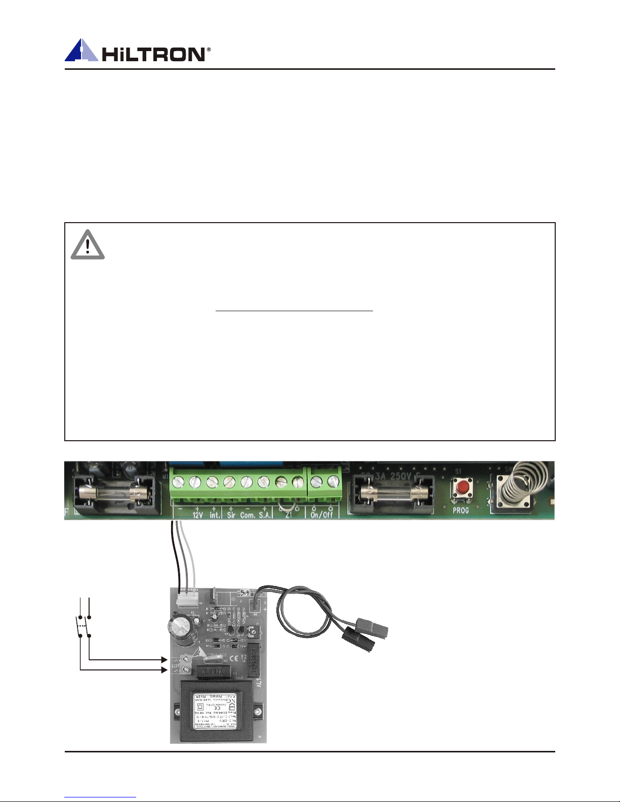
2.3 Power Supply
After the unit is fixed at the wall, connect again the H158B power supplier/battery charger
to 12V / 7Ah battery. It’s important to know that the Central Unit is powered exclusively by the
12V / 7Ah lead battery which is costantly in charge.
Look out of connection polarity to avoid damaging the product.
After the connection of the battery, you can connect the main power supply on the 220V
clamps of the power supplier/battery charger H158B.
12V / 7Ah
Battery
H158B1
CAUTION !
Main power supply has to be connected by two 1,5mmq wires coming from a
sectioning switch (i.e. a magneto-thermic protection switch), used only for the
burglar central unit.
12V / 7Ah battery must always be connected. If you want make sure of its
charge status, disconnect the main power supply and measure the tension by
a volt-meter.
Do not connect on 13Vdc services power supply output of the Central Unit
(clamp “+12V”) a load beyond 330mA.
Do not connect on sirens outputs of the Central Unit (clamp “+sir.”) a load
beyond 3A.
230V~
50Hz
Sectioning
Switch
7
InstallationH347B - User’s Manual
2.4 System Configuration and Wiring
Refer to descriptions below for connecting the clamps of H347B:
1 - 2 13Vdc output voltage. Maximum current supplied:
1 - 3 utput oltage
7 - 8 Immediate/delayed e If you don’t use, you must jumper these clamps.
9 - 10 Enabling/disabling optional command systems (i.e. by contact closure).
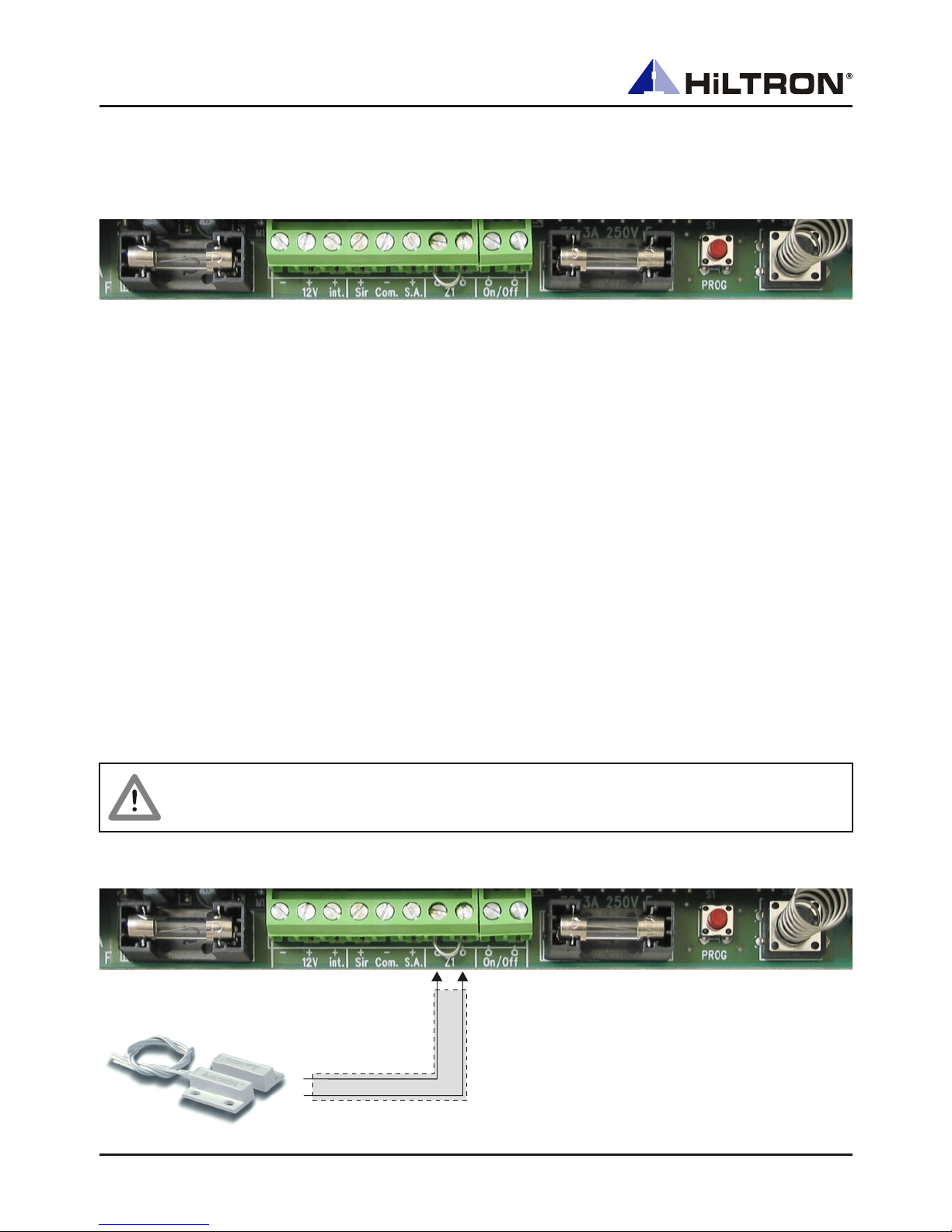
2.4.1 Zone 1 (wired)
Refer to pictures below for the connection of Zone 1, or rather of the wired zone. This zone
is delayable, so we suggest you to assign it at the door-way.
400mA max.
13Vdc o v on enabled system for telephone dialer operating.
4 - 5 13Vdc output voltage in alarm condition for additional sirens and telephone
dialer enabling.
5 - 6 13Vdc regular output voltage for the charge of optional self-powered H295G
siren. In alarm condition this voltage drops.
Zon 1.
1 2
3
4
5 6
7
8 9 10
2.4.3 Additional Sirens
self-powered sirens type H295G.
2.4.2 Telephone Dialers
CAUTION!
If the Zone 1is not used, jumper the clamps (7) and (8) "Z1".
H330C
8
 Loading...