

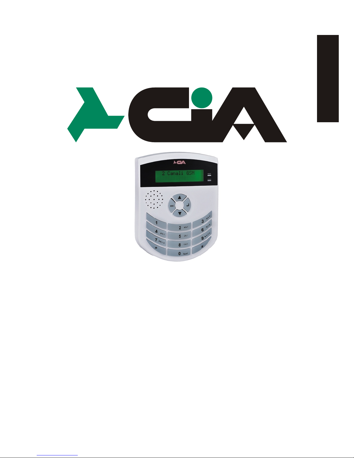
GSM phone dialers
with vocal messages
TDC28 - TDC36 - TM26GSM
TM66GSM - ERMES2
USER’S MANUAL
(for circuits 622aMA-2 and ).xx 711aMA-1.xx
ITALIANO
ENGLISH

TDC28 -TDC36-TM26GSM-TM66GSM-ERMES2
User’s manual
2 3
Index
Chapter 1 - Introduction ....................................................................3
1.1 Functional characteristics .................................................................................3
1.2 Technical characteristics ..................................................................................3
Chapter 2 - Installation ......................................................................4
2.1 Connections TDC28.........................................................................................4
2.2 Connections ERMES2-TM66GSM-TM26GSM-TDC36.................................... 5
Chapter 3 - Programmation...............................................................6
3.1 Accessing programming.................................................................................. 7
3.2 Address book...................................................................................................8
3.3 Vocal messages.............................................................................................10
3.4 TXT/SMS messages......................................................................................12
3.5 Channels........................................................................................................14
3.6 Output............................................................................................................ 16
3.6.1 Mode................................................................................................. 17
3.6.2 Reference input.................................................................................17
3.6.3 Pulse duration................................................................................... 18
3.7 Parameters.................................................................................................... 18
3.7.1 Remote control..................................................................................19
3.7.2 Language selection........................................................................... 19
3.7.3 Reply pulse....................................................................................... 20
3.7.4 Numbers of calls................................................................................20
3.7.5 Numbers of messages... ...................................................................21
3.7.6 Beep no Registr................................................................................. 21
3.8 Codes.............................................................................................................21
3.9 Info................................................................................................................. 23
3.10 Reset default settings................................................................................... 23
Chapter 4 - Operation............................................................................24
4.1 General description of operation................................................................... 24
4.2 Local control.................................................................................................. 25
4.2.1 Stop cycle..........................................................................................25
4.2.2 Stop all cycles....................................................................................25
4.2.3 Output command...............................................................................26
4.2.4 Input status........................................................................................27
4.2.5 Out of order....................................................................................... 27
4.2.6 In service...........................................................................................28
4.2.7 Telephone......................................................................................... 28
4.2.8 Remote control..................................................................................29
1 Introduction
1.1 Functional characteristics
1.2 Technical characteristics
! Built-in microphone
! Dual Band GSM module
! Delay on input singularly programmable
! Possibility to assign each phone number singularly to one channel, some
! Antiopening and antitearing protection tamper
! Multiple languages: Italian, English, French, German, Spanish, Portuguese
! Indication of the intensity of GSM signal and of the telephone manager
! Message repetitions and calling cycles settable
! 'Out of order' function
! CLIP function :One output control by one ring (call without answer) from one
Introduction
1 Introduction
1.1 Functional characteristics
1.2 Technical characteristics
! Built-in microphone
! Dual Band GSM module
! Delay on input singularly programmable
! Possibility to assign each phone number singularly to one channel, some
channel or to all channels
! Antiopening and antitearing protection tamper
! Multiple languages: Italian, English, French, German, Spanish, Portuguese
! Indication of the intensity of GSM signal and of the telephone manager
! Message repetitions and calling cycles settable
! 'Out of order' function
! CLIP function :One output control by one ring (call without answer) from one
phone number in SMS address book, with automatic return of confirming ring
TDC36 TM26GSMERMES2TDC28
TM66GSM
Remote ambient listening
SMS messages (128 car.) activation each channel
Short texts (16 chars) for viewing
the State of the inputs and outputs
Operators codes settable
Power supply voltage
Max. current consumption
Consumption in st/by
Vocal messages (16 sec.)
State vocal messages (2sec.) for input/outputs
state monitoring
Address book
Bay for battery
Power supply / power set
Input channels programmable as pulse or status
mode, conditionable to the others
Input channels conditioning INT
Programmable relay outputs
100mA open collector programmable outputs
External box
Dimensions (W)
Dimensions (H)
Dimensions(D)
2 6 2 6
12 28 12 28
MASTER and COMMANDOS code
12Vdc 10%
400mA
70mA
3 7 3 7
12 28 12 28
16 numbers
12V7Ah (non incl.)
AL1 (included)
2 6 2 6
2
1
1
5 1
5
ABS
metal
140mm
115mm
29mm
280mm
230mm
96mm
285mm
95mm
17mm

4
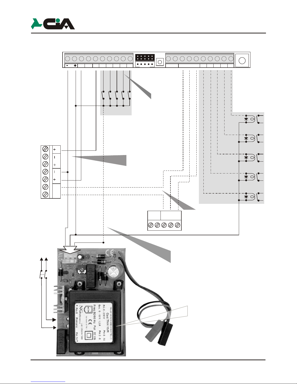
2 Installation
2.1 Connections TDC28
V R
C NC NA
Uscita
LED
Relay 2
(optionally)
Electronic key
Proximity key
Burglar
central unit
Sir
12Vcc12V int
Chiave
TDC28
GND
in
-
GND
IN
K2
INT
2
TAMPER
INT
1
IN
K1
GND
in
-
GND
C
+ 12V -
NANC
OUT1
OUT
2
1.Important:
Use any GSM phone for
delete the access code (PIN code)
that enables the use of the SIM CARD.
To insert or remove the terminal blocks
perform the operation as shown in figures
2. Insert the SIM card inside the module taking into account
the beveled corner.
3.NOT FORCING THE SIM.
Insert with sweetness the male connector of the antenna
on the phone dialer as shown in the figure.
V R
C NC NA
Uscita
LED
Electronic key
Proximity key
GND
in
-
GND
C
+ 12V -
NANC
OUT1
OUT
2
1.Important:
Use any GSM phone for
delete the access code (PIN code)
that enables the use of the SIM CARD.
The base of TDC28 can be mounted on a
standard wall-mounted box “503” type.
For the antitheft protection, fixing
with the screw in dotation
ERMES2
TM66GSM
TDC36
TM26GSM
Burglar
central unit
Installation
IN4
IN5
IN6
only
for ERMES2
OUT3
OUT4
OUT5
OUT6
only
in the ERMES2
and TDC36
230V~
50Hz
Switch
2.2 Connections ERMES2 / TM66GSM / TDC36 / TM26GSM
Installation
IN3
IN4
IN5
IN6
only
for ERMES2
OUT3
OUT4
OUT5
OUT6
for ERMES2
SETUP
K4K6K5
C1 NC1NA1
Tamper
U4
U6
U2 U3
U5
OUT2
This connection allows the input and
output of the burglar alarm whether
with the electronic key as
with phone dial.
NOTE: If you use only the phone dial
is necessary to connect only the
output C and NC of the Relay1 of the
phone dial on Key terminals of the
central unit.
TDC28 -TDC36-TM26GSM-TM66GSM-ERMES2
User’s manual
Installation
5
Installation
ERMES2
TM66GSM
TDC36
TM26GSM
Burglar
central unit
IN2
IN3
IN4
IN5
IN6
IN1
Black
Red
White
INT1
only
for ERMES2
OUT3
OUT4
OUT5
OUT6
for ERMES2
and TM66GSM
only
in the ERMES2
and TDC36
Installation
IN4
IN5
IN6
only
for ERMES2
OUT3
OUT4
OUT5
OUT6
only
in the ERMES2
and TDC36
Net
230V~
50Hz
Switch
Int1 K1Int2
12V
SETUP
K4
K6
K2 K3
K5
C1 NC1NA1
Tamper
U4
U6
U2 U3
U5
OUT2
2.2 Connections ERMES2 / TM66GSM / TDC36 / TM26GSM
Chiave
12V int
12Vcc
Sir
Installation
IN3
IN4
IN5
IN6
only
for ERMES2
OUT3
OUT4
OUT5
OUT6
for ERMES2
SETUP
K4K6K5
C1 NC1NA1
Tamper
U4
U6
U2 U3
U5
OUT2
V R
NA NC C
Uscita
LED
Electronic Key/
Proximity Key
Channel 2÷6
activation
example
OUT1
ATTENTION!
In order to use the
positive outputs ‘+ Sir’ e ‘+ Int.’
Of burglar central the negative
must be in common
to the feeding of
ERMES2 / TM66GSM
This connection allows
the insertion and the not
insertion at a distance of
burglar central unit united to
uses of electronic key.
This connection, if used, consents
to send to one of inputs (K1,K2...) A positive one
of reference in presence of main voltage 230 Vac.
Setting up in the programming the input like
“Positive Level”, to lacking the mains voltage
telephone dialer will send the message of relative alarm.
6 7
CH2 DisabledDD
25Y ABCDA
25Y ABCDA
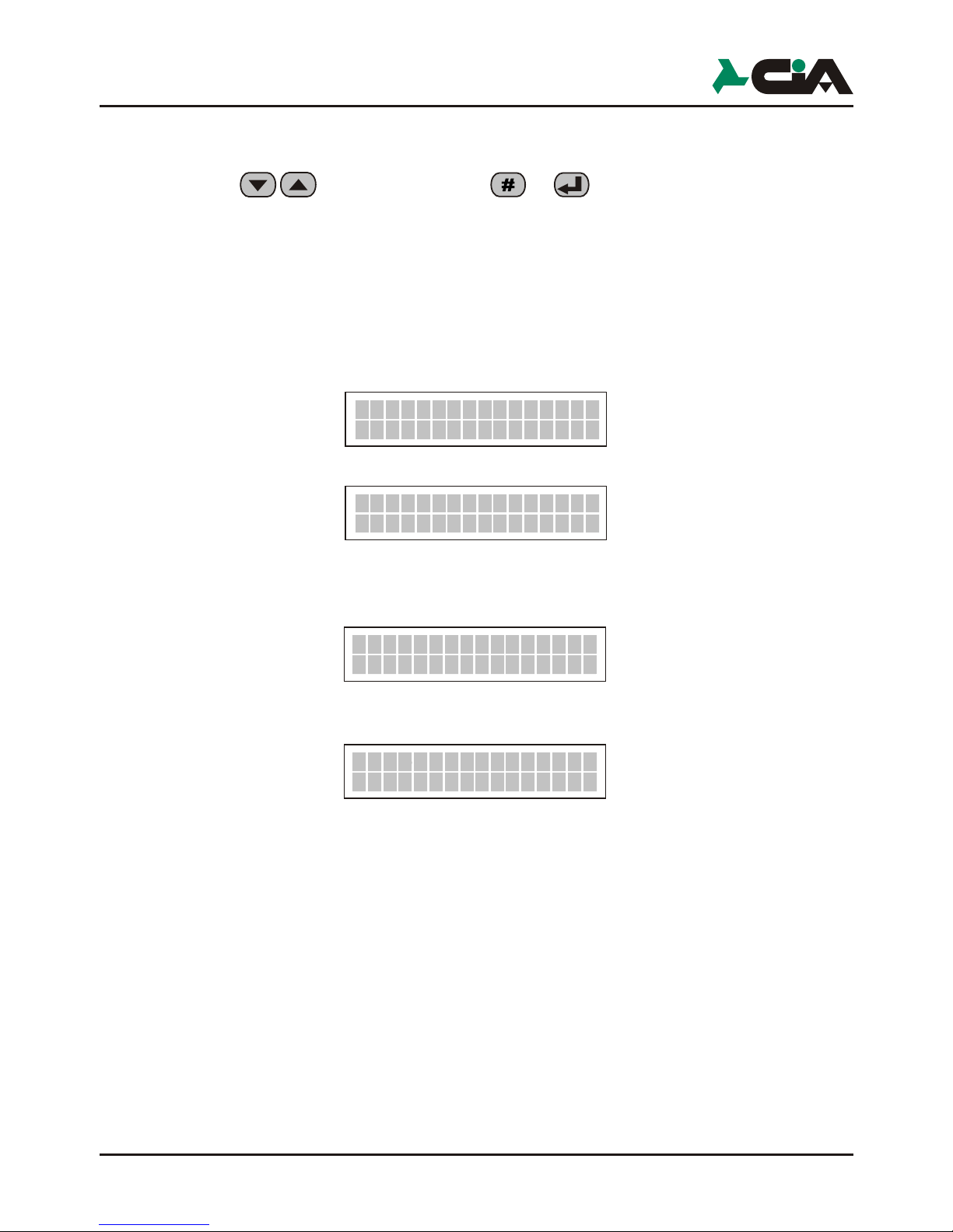
3 Programmation
After the installation and the power to the telephone dialer select your language
using the keys and confirm with or .
The disponible language :
After selecting language, the telephone dialer, is able to stand/by show status,
rolling, the two input channels (default CH1 and CH2 is enabled is disabled).
This will be displayed:
which alternates with:
After inserting the SIM the telephone dialer will register to the network of the
provider, you displayed :
When is effected the registration, is displayed :
NOTE :
To activate a series of calls on a channel you must have enabled at least one
phone number: "Ch1 Heading OFF" indicates that the channel 1 is not associated
with any telephone number or for voice calls, nor for sending SMS and result notoperative.
Italian, English, French, Spanish, Portugues,
German.
To operate in the various menu you can use the keys until you see, for
example:
and confirm with or
or use the shortcut key (for example Programmation).
3.1 Accessing programming
The programmation of the telephone dialer is allowed only with local keyboard, digit
the MASTER code ( )
Digit the code (MASTER code default)
Press the key (Programmation)
The programmation of the telephone dialer includes:
1 - Address Book 16 address book numbers, that will be sent Vocal Messages
3 - Vocal Mess. 3 from 12 sec. (Common message, Channel 1, Channel 2)
4 - Text/SMS Mess. IN and OUT description of channels and of other inputs and
5 - Channels Impostation of the input, setting conditions and delays in
6 - Output Impostation of the outputs.
7 - Parameters In this section are given in the operating parameters of the
8 - Codes Variation of MASTER Code and of COMMANDS code.
0 - Info Visualization info the dialer model and of the firmware.
This applies both in the Main Menu to access a submenu, either within the various
submenus, where you can also use key shortcuts to select a particular parameter,
a given plant, and so on.
Is possible anyway abandon the programmation with press the key or
10YOABCD
Registration...
TDC28 -TDC36-TM26GSM-TM66GSM-ERMES2
User’s manual
Ch1 OffRubric
Ch1 OffRubric
Ch1 OffRubric
Ch1 OffRubric
To operate in the various menu you can use the keys until you see, for
example:
and confirm with or
or use the shortcut key (for example Programmation).
NOTE In the manual, in most cases, you will use the mode with the
keyboard shortcuts. Thus, while consulting the manual, you can
use the sequence of the key for each Paragraph next to quickly
access the programming described in it.
3.1 Accessing programming
The programmation of the telephone dialer is allowed only with local keyboard, digit
the MASTER code ( )
Digit the code (MASTER code default)
Press the key (Programmation)
The programmation of the telephone dialer includes:
1 - Address Book 16 address book numbers, that will be sent Vocal Messages
3 - Vocal Mess. 3 from 12 sec. (Common message, Channel 1, Channel 2)
+ 12 status messages of 2sec. seconds each for the TDC28
and TM26GSM.
7 from 12 sec. + 28 status messages for ERMES2 and
TM66GSM
4 - Text/SMS Mess. IN and OUT description of channels and of other inputs and
outputs (mess. max of 128 characters for CH1 and CH2; 16
for all other K1, K2,I NT1, INT2,OUT1 e OUT2).
5 - Channels Impostation of the input, setting conditions and delays in
activation.
6 - Output Impostation of the outputs.
7 - Parameters In this section are given in the operating parameters of the
telephone dialer.
8 - Codes Variation of MASTER Code and of COMMANDS code.
0 - Info Visualization info the dialer model and of the firmware.
This applies both in the Main Menu to access a submenu, either within the various
submenus, where you can also use key shortcuts to select a particular parameter,
a given plant, and so on.
Is possible anyway abandon the programmation with press the key or
PROGRAMMING
1-Rubric
6
5
7
8 8
6
5
7
8
8
6
5
7
8
Programmation
8-PROGRAMMATION
Init GSMo
8
8
Num.001
Number00001
6
5
7
8 8
1
6
5
7
8
8
3.2 Address Book
In this menu you can enter or edit the phone numbers that the controller should
call in case of activation of a channel.
Digit the code and press in sequence and is displayed
digit one button or :
Press the button
Digit the number that you want to store, and press .
When you have stored the phone number, digit :
Press the button
Digit a name to memorized (for example) :
Press for memorize.
NOTE: The maximum length of the name to be inserted is 16 characters.
NOTE: For delete or change a character, use . The same applies to
select and type the new character.
Press the button and confirm with or is displayed :
Num.001
Name
NotoProgrammed
Number
1
Number
0000000000000>
Num.00100000000>
Name
MisteroRED
2-Name
Vocal
Channel >--oooooo
For bind a channel to the number, press the key that corresponds to the channel
(example channel 1; for channel 2, etc.). To delete the assignment simply
retype the channel number is displayed:
Once you have assigned one or more channels in the phone number box, type the
key is displayed:
Press the corresponding button for the channel to which you want to assign the
sms.
Once you have assigned one or more channels, press is displayed:
In this menu item you can place the operation which the controller performs when
receives a call from the number recorded in the address book.
TDC28 -TDC36-TM26GSM-TM66GSM-ERMES2
User’s manual
call
9
Programmation
For bind a channel to the number, press the key that corresponds to the channel
(example channel 1; for channel 2, etc.). To delete the assignment simply
retype the channel number is displayed:
Once you have assigned one or more channels in the phone number box, type the
key is displayed:
Press the corresponding button for the channel to which you want to assign the
sms.
Once you have assigned one or more channels, press is displayed:
In this menu item you can place the operation which the controller performs when
receives a call from the number recorded in the address book.
2
SMS
Channel >--oooooo
SMS
Channel >1-oooooo
1
Clip
--Off
Channel >1-oooooo
1
2
3
4
5
6
7
8
9
OUT1oOFF --
OUT2oOFF -OUT3oOFF --
OUT4oOFF -OUT5oOFF --
OUT6oOFF -OUTXoON --
OUTXoOFF CR
--
0
OFF
OUTXoOFF
Select the output 1
Select the output 2
Select the output 3
Select the output 4
Select the output 5
Select the output 6
Prepares a command ON the output slected
Enable the confirmation call
Disabled the CLIP
Prepares a command OFF the output slected
Vocal call
*
#oRec
6
5
7
8 8
3
6
5
7
8
3
8
>>>>>>>>>>>>>>>>
>>>>>>>>>>>>>>>>
Msg. COMUNE
Canale 1
Canale 2
Indication on the first line of the display
Alarm
messages
Duration:
Utilize:
16 sec.
16 sec.
16 sec.
It is broadcast for first during
a call alarm loop
Follows the common message
When you enable channel 1
Follows the common message
When you enable channel 2
8
25YoABCD
CH1
Completed the setting to the number entered, press the button once to go
back and select the next number to be stored using the keys.
Repeat the same procedure for the other numbers.
NOTE: If no number is entered in the address book and assigned to one of the
channels enabled, the telephone dialer is displayed:
3.3 Vocal Mess.
The vocal messages are those that the dialer uses to signal an alarm or the status
of the inputs and outputs the user during a dial-up connection.
Enter the default Code (MASTER),
then press (Vocal Messages) and finally the button . Is displayed:
Press and hold the button (registration) and say the message
you show :
Press the button (playback) for listen the messages
is displayed :
The following table lists the available voice messages:
NOTE: The channels displayed for models ERMES2, TM66GSM are 6
Play
The message sent during a call as a result of the activation of a channel is
composed of the common message followed by specific message channel
enabled, all repeated for as many times as indicated by the "Num" parameter
(see section 3.7.5).
The status messages are used during remote control to indicate the status of the
inputs and outputs and are transmitted as a result of an activation command
or query outputs, or as a result of a query command inputs.
NOTE: In ERMES2 and TM66GSM models, voice messages are a total of 12
Once registered, select the next voice message to be stored using the keys
and then press the button and repeat the same procedure above to
store just the other messages.
The following table lists the available status messages:
TDC28 -TDC36-TM26GSM-TM66GSM-ERMES2
User’s manual
Rubric Off
COMMON
Msg.
COMMON
Msg.
COMMON
Msg.

1110
The message sent during a call as a result of the activation of a channel is
composed of the common message followed by specific message channel
enabled, all repeated for as many times as indicated by the "Num" parameter
(see section 3.7.5).
The status messages are used during remote control to indicate the status of the
inputs and outputs and are transmitted as a result of an activation command
or query outputs, or as a result of a query command inputs.
NOTE: In ERMES2 and TM66GSM models, voice messages are a total of 12
inputs + 4 INT inputs + 12 for the outputs.
Once registered, select the next voice message to be stored using the keys
and then press the button and repeat the same procedure above to
store just the other messages.
The following table lists the available status messages:
2 sec.
2 sec.
2 sec.
2 sec.
2 sec.
2 sec.
2 sec.
2 sec.
2 sec.
2 sec.
2 sec.
2 sec.
Status
messages
In K1 NO
In K1 SI
In K2 NO
In K2 SI
INT1 NO
INT1 SI
INT2 NO
INT2 SI
Out NO
SI
NO
SI
Out
Out
Out
1
1
2
2
Report entry
channel 1 inactive
Report entry
channel 1 inactive
Report entry
channel 2 inactive
Report entry
channel 2 inactive
Indicates the lack of tension
+ 12 volt input INT1
Indicates the lack of tension
+ 12 volt input INT1
Indicates the lack of tension
+ 12 volt input INT2
Indicates the lack of tension
+ 12 volt input INT2
Message to output OUT1
not active
Message to output OUT1
active
Message to output OUT2
not active
Message to output OUT2
active
Programmation

Irrigation
Channel2
_
>
NOTE:
When a channel is alerted, the mode dial makes a series of calls to all numbers
entered in the phonebook Voce matched to that channel and forward voice
message concerning preceded by common message. The parameter "Amount
cycles described below allows you to determine how often this cycle must be
repeated calls.
If you send the voice message you type from the remote
telephone:
the number called is excluded from the list of subsequent phone
calls.
It is advisable to insert at the end of the recording of voice messages warning a
note like: "...Enter the code and to stop receiving this alert message ".
3.4 TXT/SMS Messages
In this menu you can insert or modify the SMS that the controller sends in case
of alarm, and descriptions that appear on the display to indicate the status of
the inputs and outputs.
The descriptions will be displayed when you type on the keyboard of the
dialler/query commands to control inputs and outputs (see section 4.2.3).
Digit the default code (MASTER) , then press and finally the
button (Vocal Messages). Is displayed :
Press or is displayed :
Write a message from stored, for example :
Press the button
6
5
7
8
8
Ch.
Channel 1
1
4
0
6
5
7
8 #
0
6
5
7
848
Ch.
Channel 1
1
_
Once you have typed the message utilize the button press or . .
The following is a table of inputs and outputs that are displayed at the top of the
display:
NOTE : For ERMES2/TM66GSM Combinatorial inputs In range from K1 to K6 and
TDC28 -TDC36-TM26GSM-TM66GSM-ERMES2
User’s manual

1312
Once you have typed the message utilize the button press or . .
The following is a table of inputs and outputs that are displayed at the top of the
display:
NOTE : For ERMES2/TM66GSM Combinatorial inputs In range from K1 to K6 and
exits from OUT1 to OUT6.
Description channel that will be sent via SMS (Ch1/Ch2)
TDC28, TDC36, TM26GSM/(Ch1-6 Ch) ERMES2, TM66GSM
Description for channel 1 input not active
Description for channel 1 input active
Description for channel 2 input not active
Description for channel 1 input active
Description for voltage + 12 volt on INT1 not present
Description for presence of voltage of + 12 volt on INT1
Description for voltage + 12 volt on INT2 is not present
Description for presence of voltage of + 12 volt on INT2
Description for output out 1 inactive
Description for output out 1 active
Description for output out 2 active
Description for output out 2 active
Channel
In K1 SI
In K2 NO
In K2 SI
INT1 NO
INT1 SI
INT2 NO
INT2 SI
Out NO
SI
NO
SI
Out
Out
Out
1
1
2
2
1
In K1 NO
Programmation

3.5 Channels
In this menu you can set how should be activated channel telephone dialer.
Digit the code (MASTER) and then press the button and
after the button (Vocal Messages). Is displayed :
Press the button or , is displayed :
Press still or , is displayed :
Choose between activation modes listed in the table below, as a condition of the
channel you must alert using the keys
and confirm with the button or .
6
5
7
858
6
5
7
8
8
CHANNEL
1
Channel
SELECT
5
1-Activation
1
Channel
1-Activation
NO
Impulse
Once you have chosen the way the selected channel becomes alarmed, you can
choose whether to condition or not this input to INT1, INT2 or In K1, K2. "Make
"an input means do so depend on the presence of a positive voltage to make it
operational; the lack of this entry is not operational or, if it fails after the activation
of the input cycle shutdown in progress.
For example for use with a central alarm connected with output SIR connected on
input K1 and output + INT on INT1 on can be programmed for Channel 1 :
- Activation = Impulse NO
- Input INT = INT1
In this way the cycle of calls in the event of an alarm only if the central unit is
inserted (INT + 12V is present) and to stop the telephone dialer simply disconnect
the central unit.
Programming for Channel 1 :
- Activation = Impulse NO
- Input INT = Off
the cycle of calls in case of alarm, but to stop the dialler you must act directly on
the controller itself (locally or remotely) or even wait until the end of the cycle of
calls.
Press the button is displayed :
Use to choose which input (IN K1; INT1; IN K2; INT2 for TDC28 and
TM26GSM and K3 until IN K6 for ERMES2 and TM66GSM) use as "Input INT".
Once you have chosen the entry, press or .
NOTE: Is not possible use In K1 as "Input INT" of channel 1 and In K2
as "Input INT" channel 2 etc.
GSM.............
Disabled
CH1
1-Attivazione
Active
Not
1-Atctivation
NC
Level
0
12V
Impulso NO
0
12V
Impulso NC
0
12V
Livello NO
Livello NC
0
12V
1-Activation
NA
Level
1-Activation
NC
Impulso
1-Activation
NA
Impulso
The channel is activated from the presence of a
positive 12Vcc to the input of the channel; the
cycle of calls comes started and carried out until
the term, if not interrupted through commandos.
The channel is activated from the absence of a
positive 12Vcc on the input of the channel;
the cycle of calls comes started and carried
out until the term, if not interrupted
through commandos
The channel is activated from the presence
of a positive 12Vcc on the input of channel;
the the cycle of calls comes executed until the term
if not interrupted from a command or coming to lack
the positive one on the income
The channel is active to lacking the positive one 12Vcc
on the income of thechannel; the cycle of calls comes
activated and carriedout until the term, if not
interrupted through commandos or the restoration
of the positive one 12Vcc on the income
The active channel in no condition and on the first
one display of the combinatore is not come visualized:
TDC28 -TDC36-TM26GSM-TM66GSM-ERMES2
User’s manual

1514
Once you have chosen the way the selected channel becomes alarmed, you can
choose whether to condition or not this input to INT1, INT2 or In K1, K2. "Make
"an input means do so depend on the presence of a positive voltage to make it
operational; the lack of this entry is not operational or, if it fails after the activation
of the input cycle shutdown in progress.
For example for use with a central alarm connected with output SIR connected on
input K1 and output + INT on INT1 on can be programmed for Channel 1 :
- Activation = Impulse NO
- Input INT = INT1
In this way the cycle of calls in the event of an alarm only if the central unit is
inserted (INT + 12V is present) and to stop the telephone dialer simply disconnect
the central unit.
Programming for Channel 1 :
- Activation = Impulse NO
- Input INT = Off
the cycle of calls in case of alarm, but to stop the dialler you must act directly on
the controller itself (locally or remotely) or even wait until the end of the cycle of
calls.
Press the button is displayed :
Use to choose which input (IN K1; INT1; IN K2; INT2 for TDC28 and
TM26GSM and K3 until IN K6 for ERMES2 and TM66GSM) use as "Input INT".
Once you have chosen the entry, press or .
NOTE: Is not possible use In K1 as "Input INT" of channel 1 and In K2
as "Input INT" channel 2 etc.
INT1
2-Input INT
2
Programmation

8
6
5
7
868
6
5
7
8
6
Out
OUTPUT1SELECTION
Po insert a delay between the activation of the channel signal and the actual
beginning of the cycle of calls.
Press button is displayed :
Confirm with the button or
Type the desired delay in seconds (maximum of 9999 2:46 ' 39 "), and then
press or .
NOTE: If during the time delay is an event that cancels the cycle, the delay
timer is reloaded, and any new activation points start counting again.
3.6 Output
In this menu you can set the operating parameters of outputs that are: Mode,
Reference Input and Pulse duration.
Digit (Master code) and in sequence and , is displayed :
Select exit (from 1 to 2 to TDC28, TDC36, TM26GSM and from 1 to 6 for
ERMES2, TM66GSM) by pressing the keys and confirm with or
0000
3-Delay
3
No condition
Input channel 1
Input channel 2
Input INT 2
Input INT 1
INT1
INT2
In
Off
K1
In K2
----
3-Delay
3.6.1 Mode
Once you have selected the output you can set the behavior when it receives a
command to activate or deactivate (see also section 4.2.3)
The display visualized :
confirm with or .
3.6.2 Reference Input
The input reference (example Channel 1) is used to evaluate the output status
(active or inactive), both for the execution of commands on both outputs to
determine the indications on the display or voice messages to be sent in case of
query remotely. To access this parameter press the button
Is displayed:
Use the buttons to choose which Input Reference. " (see table) is used to
determine the status of the output. Press or .
Press the button or . Choose the “Mode” with the buttons
TDC28 -TDC36-TM26GSM-TM66GSM-ERMES2
User’s manual

1716
3.6.1 Mode
Once you have selected the output you can set the behavior when it receives a
command to activate or deactivate (see also section 4.2.3)
The display visualized :
, and
confirm with or .
3.6.2 Reference Input
The input reference (example Channel 1) is used to evaluate the output status
(active or inactive), both for the execution of commands on both outputs to
determine the indications on the display or voice messages to be sent in case of
query remotely. To access this parameter press the button
Is displayed:
Use the buttons to choose which Input Reference. " (see table) is used to
determine the status of the output. Press or .
Press the button or . Choose the “Mode” with the buttons
1
6
5
7
868
1
Mode
Out 1
INT1
Input
Riferim.
6
5
7
868
1 2
2
TOOGLE
Modo
IMPULSE
Mode
ON/OFF
Mode
ON command inverts the state of the output is this result disactive
and have not effect if result activated. In other way the OFF command
invert the output only if this result activated. For estimate the condition
of the output (if is activated or disactivated), the combiner fa reference
at the condition of the output same,or of the input of reference in
agreement to set up how much in the option “Input Refer.” (see par. 3.6.2).
The ON command generates an impulse on the output if this result disactivated
and have not effect if result activated. In other way the command OFF
invert the output only if this result activated. Also in this modality the state
of the escape (active or disactive) depends from as the parameter
for the income of reference adopts a position. The difference regarding
the previous modality consists that the operation that comes executed is not
that one of the commutation, but is the generation of an impulse off-on-off,
of the duration set up in the parameter “Duration Impulse" (sees par. 3.6.3).
With this choice commandos ON and OFF have always the effect to invert
the state of the escape independently from its condition.
Programmation

3.7.1 Remote Control
With this parameter you enable/disable the mode dial to accept remote control.
NOTE:
If you disable this setting, the telephone dialer does not respond to calls from
outside and does not accept activation commands or questioning of the inputs
and outputs during the alarm call.
Digit (MASTER code) and in sequence the buttons: ; and
is displayed :
To activate or deactivate the parameter you can press one of or .
3.7.2
Digit and in sequence the buttons ; and :
NOTE: To the first ignition, the telephone dialer demands the choice of the
Select the language with the buttons and confirm with or .
In this menu you can change the language that the phone dialler uses for
indications on the display.
4
3
3.6.3 Pulse duration
Set the duration of the pulse generated on output expressed in seconds.
If the output (for example Channel 1) is not programmed to pulse this value is
ignored.
To access the parameter, press button is displayed :
Press button or is displayed :
Select the pulse duration with the keypad, from 01 to 99 seconds and confirm with
or .
3.7 Parameters
In this section you set the operating parameters of the telephone dialer.
Digit ( MASTER code) and in sequence and is displayed :
Utilize to select the parameter to be set then press or .
NOTE: In the subparagraphs that follow is explained the operation of individual
parameters and how to get there from the main menu directly with a key
combination.
01
Impulse Duration
--
8
6
5
7
8
7
6
5
7
878
On
Remote
6
5
7
868
1 3
In K1
In K2
Int 1
No Input
Int 2
In this case the output does not make reference to an input, but
the state of assets and disactive is determined from the same
condition of the output: Active OUT1 when the relay of output
it connects the clips C and NA and OUT2 is active when through
the clip can circular current towards the feeding negative
The output makes reference the INT1 input
The output makes reference the input INT2
The state of the output is determined with reference to the
K1 input : with a present tension of 12V on the K1 in putthe dialer
it considers the active output, while in lack of such
tension currency the disattiva output
The output makes reference the K2 input
TDC28 -TDC36-TM26GSM-TM66GSM-ERMES2
User’s manual
Impulse Duration
Controls

1918
3.7.1 Remote Control
With this parameter you enable/disable the mode dial to accept remote control.
NOTE:
If you disable this setting, the telephone dialer does not respond to calls from
outside and does not accept activation commands or questioning of the inputs
and outputs during the alarm call.
Digit (MASTER code) and in sequence the buttons: ; and
is displayed :
To activate or deactivate the parameter you can press one of or .
3.7.2
Digit and in sequence the buttons ; and :
NOTE: To the first ignition, the telephone dialer demands the choice of the
Select the language with the buttons and confirm with or .
Language selection
language to use. The available languages are: Italian, English, French,
Spanish, Portuguese, German.
In this menu you can change the language that the phone dialler uses for
indications on the display.
6
5
7
8
English
Language
5
7
8
6
5
7
878
5
6
5
7
8
7
8
4
On
6
5
7
878
4
Programmation
Remote Controls

3.7.5 Number of messages
This parameter indicates the number of times the voicemails (common message +
channel message) are repeated for each call.
Digit (MASTER code) and sequence the buttons: ; and
is displayed :
Then press or is displayed :
Digit the number of vocal messages (max. 9) and confirm with or .
NOTE:
After a few seconds from the end of messages unless the remote control
communication is interrupted.
3.7.6 Beep no Registr.
Enabling this parameter, the system emits a beep in the absence of GSM signal
every 4 minutes.
Digit (MASTER code) and in sequence the keys : ; and
for displayed
Press or for active or disactive this parameter.
NOTE: By default this parameter is set to OFF.
3.8 Codes
The telephone dialer manages two codes both of four number, one MASTER and
one COMMANDS.
Using the MASTER code you have total control of the dialer with access to local
and remote commands and the ability to program the same dialer.
Using instead the COMMANDS code there are the limitation: not possible the
command for Stop all Cycles of allarm,Out of order and remittance in order,access
at the programmation and at the Telephone function.The remote commands of
Stop cycle in course,Stop total cycles,Listen of remote withspeakerphone.
3.7.3 Reply pulse
Indicates the number of rings that the dialer waits before answer the call when
remote control is enabled.
Digit (MASTER code) and sequence the buttons: ; and
is displayed :
Press the buttons or is displayed :
Select the number of pulses from 0 ÷ 40 seconds and press or .
NOTE:
The telephone dialler does not accept a number over 40. If you set the mode dial
00 not answering external calls.
3.7.4 Number of calls
This parameter sets how many attempts to call the dialer performs for
each issue of the heading in an alarm cycle.
Digit (MASTER code) and sequence the buttons: ; and
doafter confirm with or is displayed :
digit or is displayed :
Select the number of calls (from 1 at 9) and confirm with or
NOTE :
If during connection you give from the phone connected to a command "STOP
CURRENT CALL" (see section 4.2.8), the call is never repeated in later in the
cycle. With a command of "STOP CURRENT CYCLE" or "STOP ALL CYCLES”,
no call is executed for the current cycle or for all active cycles (see section 4.2.8).
6
5
7
8
6
5
7
8
3
No. Calls
_
No. Calls
Reply
03
6
7
8
__
7
7
8
6
5
7
878
6
6
5
7
878
7
TDC28 -TDC36-TM26GSM-TM66GSM-ERMES2
User’s manual
Impulses
Reply Impulses
of
of

2120
6
5
7
8
7
8
9
On
Beep Reg.
No
6
5
7
878
9
6
5
7
8 88
3.7.5 Number of messages
This parameter indicates the number of times the voicemails (common message +
channel message) are repeated for each call.
Digit (MASTER code) and sequence the buttons: ; and
is displayed :
Then press or is displayed :
Digit the number of vocal messages (max. 9) and confirm with or .
NOTE:
After a few seconds from the end of messages unless the remote control
communication is interrupted.
3.7.6 Beep no Registr.
Enabling this parameter, the system emits a beep in the absence of GSM signal
every 4 minutes.
Digit (MASTER code) and in sequence the keys : ; and
for displayed
Press or for active or disactive this parameter.
NOTE: By default this parameter is set to OFF.
3.8 Codes
The telephone dialer manages two codes both of four number, one MASTER and
one COMMANDS.
Using the MASTER code you have total control of the dialer with access to local
and remote commands and the ability to program the same dialer.
Using instead the COMMANDS code there are the limitation: not possible the
command for Stop all Cycles of allarm,Out of order and remittance in order,access
at the programmation and at the Telephone function.The remote commands of
Stop cycle in course,Stop total cycles,Listen of remote withspeakerphone.
6
5
7
8
6
5
7
878
8
7
8
8
Programmation
3
No. Messagesof
_
No. Messagesof

Digit and press the button
Is displayed :
Press the button or is displayed :
Digit the MASTER code from memorize, and press the button or .
Once the MASTER code has been assigned, you can to assign the COMMANDS
code.
Utilize the buttons for search the COMMAND code voice :
Press or is displayed :
Digit the COMMAND code from memorize and press the buton or for
confirm.
NOTE:
If the code is not enabled for access to a menu, “NOT PERMITTED” will
appear on the display.
NOTE:
The maximum lenght of both the MASTER code and the COMMANDS code to
be inserted is 4 numbers.
Should one of the MASTER code, it is possible to directly access the
combiner programming by holding down the SETUP key for 15 seconds (see
para 2.1).
CODE SELECTION
MASTER
MASTER
----
SELEZ. CODICE
CODICE COMANDI
COMMANDS CODE
----
8
6
5
7
8
3.9 Info
Digit (MASTER code) and in sequence the keys and
then press or is displayed :
Press buttons is displayed :
Press buttons is displayed :
3.10 Reset default settings
To return the telephone dialer to the default settings, it is necessary to carry out
the following sequence:
- Remove the power
- Keep the setup button pressed (see )
- Return power to the dialer
- Release the setup button
- Press the button 5 times before 10 seconds are up
The default setting are:
This section gathers together useful information for the identification of the
combiner model and the firmware release. This information may be requested by
technical assistance in order to identify the product more easily and give
appropriate suggestions for its use.
TDC28 -TDC36-TM26GSM-TM66GSM-ERMES2
User’s manual
CODE
CODE

2322
6
5
7
8
Model
2 Channel GSM
0
8
IMEI...
0000000000000000
Rel.
619aSW-1.01
Firmware
3.9 Info
Digit (MASTER code) and in sequence the keys and
then press or is displayed :
Press buttons is displayed :
Press buttons is displayed :
3.10 Reset default settings
To return the telephone dialer to the default settings, it is necessary to carry out
the following sequence:
- Remove the power
- Keep the setup button pressed (see )
- Return power to the dialer
- Release the setup button
- Press the button 5 times before 10 seconds are up
The default setting are:
This section gathers together useful information for the identification of the
combiner model and the firmware release. This information may be requested by
technical assistance in order to identify the product more easily and give
appropriate suggestions for its use.
par. 2.1
6
5
7
8
8
0
Address book
Description for address book
Vocal messages
Channel 1
Channel 2 - 6
Output 1
Output 2
Remote control
Reply pulse
Number of calls
Number Messagges
MASTER code
COMMAND code
nessun number programmed
“Number 01...16”
All cancel
Activation: Impulse NA; Input INT: In INT 1; Delay: 0000
Text messagges
description equal to the first line of the display
Activation: No active; Input INT: Off; Delay: 0000
Mode: ON/OFF; Input Refer.: In INT1; Duration impulse: 01
Mode: ON/OFF; Input Refer.: No Input; Duration impulse: 01
ON
03
3
3
5678
1234
Language
unchanged
Programmation

24
4 Operation
Use of combiner is made easier by the presence of the display which provides
information on the activities and status of the combiner. The backlight of the
display is automatically controlled: this activates when the user presses any key
or when a channel is activated, and it turns off 20 seconds following the end of
any operation.
The information is displayed on two lines; the first displays those relative to the
operations of the combiner on the telephone line, while the information on the second
relates to the status of the two channels.
First line of the display:
! Init GSM.... Initialization of the module of telephone logon GSM
! INSERT SIM The combiner attends the insertion of one SIM card
! REGISTRATION.. Attempt of recording on the telephone net in course
! 20¥ ABCD It indicates the happened logon with the specified
telephone manager and marks it in particular the
intensity of marks them (from 1 to 31) with the symbol
¥ blinking
! 20¥ Call.. In course an attempt of telephone call
! 20¥ Failed Call The call attempt has not had answer
! 20¥ Occupied The called number turns out occupied or the call has
been refused
! 20¥ Ship SMS Shipment of the SMS in course
! 20¥ And of call The telephone call is concluded
! 20¥ Connected Connection out telephone logon
! Called rec. Called reception telephone
Second line of the display:
! Chn Rubric off No telephone number is associated to the channel
! Chn Disabled The channel n is Not Active.
! Chn On the input programmed Input INT the tension of
12V is not present
! Chn In Attesa The channel is ready and in attended of it marks them
of activation
! Chn Interval Pause between one telephone call and the next.
! Chn Timer 0012 Counter of the time remaining between the activation
of the channel and the departure of the cycle of calls
! Remote Control Activation of the control from remote during the
connection
The activation of a channel generates a sequence of calls towards the telephone
numbers inserted in the Directory, sending the recorded voice message (common
message + channel message),which is repeated the number of times established
by the “Number of messages” parameter. The complete cycle of calls is repeated
for a number of times determined by the "Number of calls” parameter.
Interdict
4.1 General description of operation
4.2 Local control
It is possible, either by using the keypad or through programming, to interact with
the combiner so as to activate its outputs or interrogate its inputs.
combiner needs to the MASTER code (default “5678”) or COMMANDS code
(default "1234”) must be keyed.
This option stops any call cycle that has been activated on any channel. The cycle
also stops when the inputs are programmed with the “NA Level” or “NC Level”
conditions, and when the activation status is in effect (see para 3.5).
This cancels all call cycles, both the one in progress and the one on hold, and
closes the current connection.
4.2.1 Stop Cycle
Digit (default MASTER code) and press the button
is displayed :
4.2.2 Stop all Cycles
Digit (default MASTER code) and press the button
(Stop all cycles)
TDC28 -TDC36-TM26GSM-TM66GSM-ERMES2
User’s manual

25
Operation
COMMAND PERFORM.
2
6
5
7
8
4.2 Local control
It is possible, either by using the keypad or through programming, to interact with
the combiner so as to activate its outputs or interrogate its inputs.
To access the operation menu items for local control indicated below, the
combiner needs to the MASTER code (default “5678”) or COMMANDS code
(default "1234”) must be keyed.
This option stops any call cycle that has been activated on any channel. The cycle
also stops when the inputs are programmed with the “NA Level” or “NC Level”
conditions, and when the activation status is in effect (see para 3.5).
This cancels all call cycles, both the one in progress and the one on hold, and
closes the current connection.
4.2.1 Stop Cycle
Digit (default MASTER code) and press the button
is displayed :
4.2.2 Stop all Cycles
Digit (default MASTER code) and press the button
(Stop all cycles)
1 - STOP CYCLES - allows the interruption of the call cycles
2 - STOP ALL CYCLES - allows the interruption of the current call
3 - OUTPUT COMMANDS - allows the direct control of the outputs
4 - INPUT STATUS - allows the monitoring of the inputs status
6 - OUT OF ORDER - allows the combiner out of order
7 - IN SERVICE - allows combiner to be placed in service
8 - PROGRAMMATION - allows to program the combiner
9 - TELEPHONE - the local use of the combiner as a GSM telephone
0 - STOP CALL - allows the interruption of the current call
MASTER COMANDI
x
/
x
x
/
/
/
/
x
x
x
x
x
x
x
x
x
x
Code
1
6
5
7
1
8
6
5
7
2
8
6
5
7
8
COMMAND PERFORM.

97
3
132
4
3
6
5
7
8
3
6
5
7
8
132
4
Out
Anti-theft
NO
1
7
9
7 9
7
7
9
4.2.3 Outputs command or
Digit one of of the two codes or and later, the
buttons , is displayed :
Description of the status of the inputs and outputs (see par. 3.4)
Utilizze the buttons and for command the output according to its
programming (see par. 3.6):
-
-
- “IMPULSE”, both keys and
-
This gives access to interrogation and command of the outputs.If the combiner is
not allarmed and digit a code to acces,this is the voice othat appears on display:
If the output is set to “ON/OFF”, the key activates the output and the key
deactivates it.
If the output is set to “TOGGLE”, both keys and create a pulse on the
output.
If the output is set to create a pulse on the
output.
If the output is also set on "Input Refer.",the operation of the keys and
is conditioned by the status of the input reference (see para 3.6.1 and 3.6.2).
In the installation example (see para 2.1), the relay of the electronic key and the
relay of the combiner are inter-connected to exchange so as to connect and
disconnect the anti-theft system through the two devices; indeed, in this way, the
inversion of status of each of the relays provokes the connection or disconnection
of the system. This implies, therefore, that the activation of the combiner relay
DOES NOT always correspond to the connection of the system. To carry out a
connection command, it is therefore necessary to know the actual status of the
exchange through its output “+Int” connected to the input “INT” of the combiner. In
this manner, when keying for connection, the combiner will exchange the
state of just relè if it centers it them will only turn out disinserita, otherwise not will
be effect; consequently it will not come visualized the relative message to the
state of the escape relè, but but the state of income "INT" from which the relè it
depends, in order to indicate the real state of the system. Therefore, if the display
it visualizes:
This message will be relative to the “INT” input, and any command will simply
correspond to an inversion of the relay status, to display the resulting input status:
7
Anti-theft
ON
Anti-theft
OFF
4.2.4 Input status or
Digit the code (MASTER of default) or (COMMAND)
and press the button is displayed :
Use the keys or directly the keys from 1 at 6 for visualize IN K1,IN
K2...IN K6
With the utilize is possible visualize INT1 and INT2 or directly is
accessible with the buttons or .
4.2.5 Out of order
Digit the code and press is visualized for a few moments :
NOTE:
Once given this command the dialer will initial the following menu display:
NOTE:
This command is executable only with the MASTER code.
With this command, the combiner will reset all the alarm cycles to zero and does
not accept any further activations. Any telephone call in progress at the time of the
command will not be interrupted, but continues as normal until its normal
conclusion. The other functions of the combiner remain operative, including
responding to outside calls, and the command and interrogation of the inputs and
the outputs.
9
TDC28 -TDC36-TM26GSM-TM66GSM-ERMES2
User’s manual

2726
4.2.4 Input status or
Digit the code (MASTER of default) or (COMMAND)
and press the button is displayed :
Use the keys or directly the keys from 1 at 6 for visualize IN K1,IN
K2...IN K6
With the utilize is possible visualize INT1 and INT2 or directly is
accessible with the buttons or .
4.2.5 Out of order
Digit the code and press is visualized for a few moments :
NOTE:
Once given this command the dialer will initial the following menu display:
NOTE:
This command is executable only with the MASTER code.
It approaches the visualization of the state of the input.
With this command, the combiner will reset all the alarm cycles to zero and does
not accept any further activations. Any telephone call in progress at the time of the
command will not be interrupted, but continues as normal until its normal
conclusion. The other functions of the combiner remain operative, including
responding to outside calls, and the command and interrogation of the inputs and
the outputs.
In K1
Irrigation
NO
3
4214
6
5
7
8 4
6
5
7
8
3
4
2 1
4
7 8
6
5
7
8 6
6
5
7
8
6
OUT OF ORDER
I
ABCD
23Y
OUT OF ORDER
Operation

28 29
4.2.8 Remote control or
Digit the code or (COMMANDS) see ) is
displayed :
Key in from the telephone:
# 0 STOP CURRENT CALL
# 1 STOP CURRENT CYCLE
NOTE:
The combiner is able to interpret the DTMF multi-frequency tones commonly
generated by telephone apparatus, and therefore to carry out commands or
send information during a telephone connection.
“Response Pulses” is greater than zero (see para 3.7.3), it is possible to access
remote control either by telephoning the combiner directly or during an alarm call.
3.8) within approximately 10 seconds from connection if the call comes from the
remote user, or within 10 seconds from the end of the last voice message when the
call comes from the combiner.
succession (approximately 1 per second).
second line of the combiner display.
This command is executable only with the MASTER code.
Enter number
_
Call....
23Y
0123456789
Number of telephone selectioned
4.2.6 In Service
This command returns the system to its normal operation by an out-of-service
condition
Digit the code and press . I :
NOTE:
4.2.7 Telephone
Digit the code and press is displayed :
Select the telephone number and press is displayed :
The dialer waits for a response before the tenth ring, then aborts the attempt..
Per end the call, press .
NOTE:
s visualized for a few moments
This command is executable only with the MASTER code.
This allows for making a speakerphone call from the combiner in order to test the
correct operation of the telephone line.
This command is executable only with the MASTER code.
7
6
5
7
8
7
6
5
7
8
SERVICE
IN
5
6
7
8
9
5
6
7
8
9
TDC28 -TDC36-TM26GSM-TM66GSM-ERMES2
User’s manual

4.2.8 Remote control or
Digit the code or (COMMANDS) see ) is
displayed :
Key in from the telephone:
# 0 STOP CURRENT CALL
# 1 STOP CURRENT CYCLE
NOTE:
The combiner is able to interpret the DTMF multi-frequency tones commonly
generated by telephone apparatus, and therefore to carry out commands or
send information during a telephone connection.
If the “Remote Control” option is programmed to ON (see para 3.7.1) and
“Response Pulses” is greater than zero (see para 3.7.3), it is possible to access
remote control either by telephoning the combiner directly or during an alarm call.
To activate remote control, it is necessary to key in a valid access code (see para
3.8) within approximately 10 seconds from connection if the call comes from the
remote user, or within 10 seconds from the end of the last voice message when the
call comes from the combiner.
If the combiner accepts the code keyed in, it transmits three beeps in slow
succession (approximately 1 per second).
When remote control is activated, "REMOTE MANAGEMENT” appears on the
second line of the combiner display.
Interrupts the call in progress and cancels the call for the whole cycle.
With this command, the combiner carries out no further calls to the current
number during successive call cycles relative to the activation of the channel.
The combiner signals recognition of this command with 5 beeps in rapid
succession (approximately 2 per second).
This command does not end communication: it is necessary to key in the
command “# # #” to break it, or else wait for the end of the call.
Interrupts the call cycle relative to the single alarmed channel.
This command cancels the current call cycle and communicates to the
combiner not to contact the remaining numbers in the directory.
Recognition of this command is signalled by 5 beeps in rapid succession
This command is executable only with the MASTER code.
par. 3.8
REMOTE
Connected.......
MANAGEM.
6
5
7
8
2
1
3
4
6
5
7
8
2
1
3
4
Operation

30
# 2 STOP ALL CYCLES
NOTE :
# 3 OUTPUT COMMANDS (interrogation / activation of outputs)
# 4 INTERROGATION OF INPUT STATUS
Interrupts the call cycle relative to all alarmed channels.
This command stops both the current call cycle and any waiting cycle
associated with the other channel.
The combiner carries out no further telephone calls to other numbers in the
directory, but returns to a waiting state for any successive activation.
Recognition of this command is signalled by 5 beeps in rapid succession
This command is executable only with the MASTER code.
Allows for control of the outputs.
To command an output, it is necessary to select it first:
key “1” for output OUT1 or “2” for OUT2 and the combiner sends the recorded
message for the status of the selected output.
If the output is programmed in connection with a reference input (see
"Reference Input" para 3.6.2), the message transmitted is instead that relative
to the status of the reference input.
This configuration is generally used when the combiner commands the
activation of anti-theft exchanges with input INT connected to the interrupted
positive of the exchanges.
In this manner, it is possible to know the output status for connection of the
exchange by directly controlling the connection or disconnection status.
The activation command of the selected output is sent with the “7” key, and
the deactivation command with the “9” key.
Once these commands have been carried out, the combiner sends the
message relative to the new output status.
As has already been seen for control by the local keyboard, an activation
command has no effect if the output is already active, just as a deactivation
has no effect if the output status is already inactive.
If a key different to those expected for this menu is pressed, the combiner
signals the error with a long beep.
With this command, it is possible to interrogate the combiner to find out the
status of its inputs via voice messages. Three beeps are emitted on
recognition of this command.
Key 1 for the IN input
Key 2 for IN2. (3 for IN3....up to IN6 for ERMES2 and TM66GSM)
Key 7 for the INT1 input.
Key 8 for the INT2 input.
The dialer sends the recorded message for the status of the selected input.
NOTE: A long error beep is emitted when keying one of the keys not enabled
for this command.
# 5 LOUDSPEAKER MONITORING
NOTE:
This command is executable only with the MASTER code.
# 6
# 7 RETURN TO SERVICE
NOTE:
This command is executable only with the MASTER code.
### CLOSE CONNECTION
TDC28 -TDC36-TM26GSM-TM66GSM-ERMES2
User’s manual

31
# 5 LOUDSPEAKER MONITORING
NOTE:
This command is executable only with the MASTER code.
# 6
# 7 RETURN TO SERVICE
NOTE:
This command is executable only with the MASTER code.
### CLOSE CONNECTION
Permits listening to the sound in the are in which the combiner is located.
The combiner sends 3 beeps of command recognition and activates audio
connection with the remote equipment.
Key “9” to activate two way comunication with viva-voce (with increased
microphone sensitivity).
Key “7” ” to activate the loudspeaker monitoring (reduces the microphone
sensitivity).
The connection breaks after three minutes; to recommence the countdown of
the three minutes, press any key and thus generate a multi-frequency tone.
The connection is interrupted if the combiner recognises a signal from the
telephone exchange (for example, the engaged signal), or if no noise is picked
up from the internal microphone or through the connected telephone for a
period of more than 20 seconds.
OUT OF ORDER (WITH STOP OF ALL CYCLES)
This stops all operation of the combiner. It will still be possible to connect to
the combiner by remote, if permitted by the programmed parameters, and
therefore be able to return the combiner to service or else command or
interrogate the inputs and outputs, or activate remote listening.
Recognition of this is signalled by 3 beeps. Following the three beeps, it is
necessary to key in the MASTER code once again. The execution of the
command is confirmed with 5 beeps in rapid succession.
This restarts all operation of the combiner. The dialer confirms recognition
with three beeps.
On receipt of this command, accessible without keying in any access code,
the combiner transmits 5 beeps and then closes the connection. If this
command is given to terminate a connection during an alarm cycle, the user
is not excluded from the directory for the continuation of the cycle. If it is
desired that no further calls are received for the alarm cycle in progress, use
command #0 (subject to the keying in of the code) and then key ### to
terminate the call.
Operation

711ADE-1.01
EMC 2006/95/CE
BT 73/23/CEE
and subsequent amendments
CONSTRUCTOR: HiLTRON S.r.l.
ADRESS: Via Caserta al Bravo, 218 - 80144 - NAPOLI
On the appraisal of tests executed on systems rispecchianti champions the configuration works previewed
them for the use, turns out that the products:
CODE OF PRODUCTS: TDC28,TDC36,TM26GSM,ERMES2,TM66GSM
DESCRIPTION OF PRODUCTS: GSM TELEPHONE DIALER 6IN/6OUT WITH VOCAL MESSAGES
GSM TELEPHONE DIALER 2IN/2OUT WITH VOCAL MESSAGES
TRADE MARK:
they turn out consistent to the indicated directives of continuation
Declaration of conformity to the restricted limitations of the use of substance dangerous
from directive 2002/95CE (RoHS) recepita with D.lgs 25 July 2005 n°151 (Article 5).
WEEE CONFORMITY
DATE DELEGATE ADMINISTRATOR
01/06/2011
In some countries of the produced Union l it does not fall back in the field of national application
of a provision of recepimento of directive WEEE, and therefore he is not in they enforced
some obligation of collection differentiated to fine life.
DECLARATION OF CONFORMITY
The CIA logos is registered by HiLTRON Srl
Quality management system
UNI EN ISO 9001:2000
RoHS CONFORMITY
DIRECTIVES
REFERENCE NORMS
EN50081-1 ; generic norm of emission
EN50082-1 ; generic norm of immunity
EN60065 ; norm for the security of electrical equipments
connected to the net of domestic use and analogous similar use
®
PROGETTAZIONI E PRODUZIONI ELETTRONICHE
The product is in compliance with the dispositions of the directive on indicated on the restrictions
to the use of some dangerous substances in the equipment electronic electrical workers and
that is they do not contain to them in advanced concentrations to the previewed margins.
Pb
Lead free
RoHS
compliant
THE AFORESAID PRODUCTS SATISFY THE DIRECTIVES BROUGHT BACK IN TABLE
WITH REFERENCE TO THE COMMUNITARIAN NORMS.
EMC 2006/95/CE
MADE IN ITALY
TDC28 -TDC36-TM26GSM-TM66GSM-ERMES2
User’s manual
 Loading...