

Page 1

ST1800
*378502*
378502
Hilti Corporation
FL-9494 Schaan
Tel.: +423/ 2342111
Fax: +423 /2342965
www.hilti.com
Hilti = registered trademark of Hilti Corp., Schaan W 2822 0903 25-Pos. 1 1 Printed in Liechtenstein © 2003
Right of technical and programme changes reserved S. E. & O.
378502/C
Bedienungsanleitung de
Operating instructions en
Mode d’emploi fr
Istruzioni d’uso it
Gebruiksaanwijzing nl
Manual de instruções pt
Manual de instrucciones es
Brugsanvisning da
Käyttöohje fi
Bruksanvisning no
Bruksanvisning sv
Οδηγιες χρησεως
el
Kasutusjuhend et
Lietoßanas pamåcîba lv
Instrukcija lt
Page 2
1
9
2 3 4
5
6
7
8
1
2 3
4
5 6
7 8
I. II. III.
46810
5
7
911
46810
5
7
911
Page 3
9
en
It is essential that the operating instructions
are read before the tool is operated for the
first time.
Always keep these operating instructions
together with the tool.
Ensure that the operating instructions
are with the tool when it is given to other
persons.
ST1800 electric screwdriver
1. General information
1.1 Signal words and their meaning
-CAUTION-
Used to draw attention to a potentially dangerous situation which could lead to minor personal injury or damage
to the equipment or other property.
-NOTE-
Used to draw attention to an instruction or other useful
information.
1.2 Pictograms
Contents Page
1. General information 9
2. Description 10
3. Tools and accessories 10
4. Technical data 11
5. Safety precautions 11
6. Before use 13
7. Operation 13
8. Care and maintenance 14
9. Disposal 15
10. Warranty 15
11. EC declaration of conformity 16
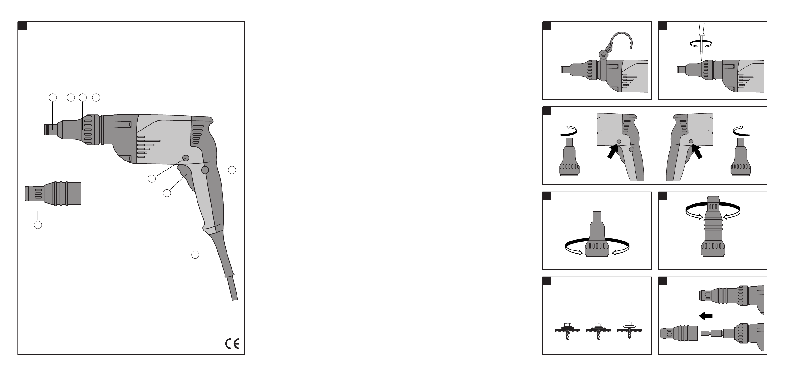
Operating controls and parts
Chuck
Protective sleeve
Push-fit connection between depth gauge and
electric screwdriver
Torque adjusting ring
Control switch lockbutton
Supply cord
Control switch
Forward/reverse pushbutton
Depth gauge adjusting ring
These numbers refer to the corresponding illustrations. The illustrations can be found on the fold-out cover
pages. Keep these pages open while studying the operating
instructions.
In these operating instructions, the ST 1800 electric
screwdriver is referred to as "the tool".
Location of identification data on the tool
The type designation can be found on the rating plate
and the serial number on the side of the motor housing.
Make a note of this data in your operating instructions
and always refer to it when making an enquiry to your
Hilti representative or service department.
Type: ST1800
Serial no.:
Warning signs
General
warning
Warning:
electricity
Obligation signs
Wear
ear
protection
Wear
eye
protection
Symbols
Read the
operating
instructions
before use.
Page 4

10
en
2. Description
2.1 Use of the tool as directed
The ST 1800 is a hand-held, electric mains-powered tool
for driving screws used to fasten sheet metal in metal
construction applications.
It is used to drive or remove the recommended metal
construction screws in the applicable materials.
The working environment may be a construction site of
any kind where metal construction work is taking place.
Use of a screw magazine is possible and provision has
been made for this (SDT 25).
Only the specified screwdriving bits, magazine and accessories may be used with the tool. The general safety precautions listed in the operating instructions must be
observed.
2.2 Main applications / torque settings
Application Screw type / diameter in mm Torque setting
Sheet metal on S-MD / 4.2 1–2
sheet metal S-MD / 4.8 1–8
Sheet metal on S-MD 51 + S-MD21 / 5.5 8–13
steel profile S-MD 53 + S-MD23 / 5.5 6–11
S-MP 52 / 6.3 4–12
Sheet metal on S-MD 55 + S-MD25 / 5.5 2–7
steel beam S-MP 53 / 6.5 8–14
Sheet metal on
wood S-MP 53 / 6.5 14 – max.
Fiber-cement
board on
steel profile S-FD 03 / 6.3 6–12
Fiber-cement
board on
steel beam S-FD 05 / 6.3 12–15
Fiber-cement
board on wood S-FD01 / 6.5 12 – max.
Sandwich panel
on steel profile S-CD 63 / 5.5 2–7
Sandwich panel
on steel beam S-CD 65 / 5.5 2–9
Sandwich panel
on wood S-CDW61 / 6.5 5–8
The above settings are intended as an approximate guideline. They result from evaluation of the characteristic
curves for the torque clutches of tools tested in quality
assurance tests and from torque values obtained from
the corresponding screw tests.
Chuck:
1
/4″ hexagon socket
Operating controls
Control switch with lockbutton
Forward / reverse pushbutton
Torque adjusting ring
Depth gauge adjusting ring
Items supplied as standard equipment
– ST 1800 electric screwdriver
– S-GT17 depth gauge (for screws with sealing
washers of up to 17 mm diameter)
– Operating instructions
– Toolbox or cardboard box (depending on version)
3. Accessories and insert tools
Scaffold hook
Belt hook
Depth gauge S-GT 23 for screws with sealing washers of up to
23 mm in diameter
Depth gauge S-GU13 for bit holder and bit (PH, PZ, TX etc.)
Hex. sockets Sockets for hex. screws (7, 8, 10, 12, 1/4″, 5/16″, 3/8″)
Decking tool SDT25 for serial fastening applications
Bits and bit holders TX, PH and TX bits; S-BH bit holder
Page 5

11
en
4. Technical data
Tool ST1800
Rated power 600 W (WH version (120 V) 670 W)
Rated voltage 100 V, 110–120 V, 220–240 V
Rated current 2.8 A at 230 V ( 6.1 A at 120 V)
Mains frequency 50 / 60 Hz
Weight of tool 1.8 kg
Dimensions (L×W×H) 308×72×265 mm
Chuck
1
/4″ hexagon socket
Speed under no load 0–1900 r.p.m.
Max. torque 22 Nm
Speed control Electronic, by way of control switch
Torque adjustment In 18 increments / 1.5–22 Nm
Forward / reverse Pushbutton
Double insulation (as per EN 50144) Protection class II Z
Mechanical clutch
Vibration-absorbing grip
Interference immunity As per EN 55014-2
Radio and television interference suppression As per EN 55014-1
Noise and vibration information (measured in accordance with EN 50144):
Typical A-weighted sound power level (LwA): 97 dB (A)
Typical A-weighted sound pressure level (LpA): 84 dB (A)
It is recommended that ear protection is worn.
Typical weighted vibration at the grips: < 2.5 m/s
2
Right of technical changes reserved!
5. Safety precautions
5.1 Basic information concerning safety
In addition to the information relevant to safety given in
each of the sections of these operating instructions, the
following points must be strictly observed at all times.
5.2 Take the necessary precautions to make the
workplace safe
● Ensure that the workplace is well lit.
● Ensure that the workplace is well ventilated.
● Keep the workplace tidy. Objects which could cause
injury should be removed from the working area. Untidiness at the workplace can lead to accidents.
● Use clamps or a vice to secure the workpiece. The
workpiece is thus held more securely than by
hand and both hands remain free to operate the
tool.
● Wear goggles and wear breathing protection during
jobs that create dust.
● Do not wear loose clothing, loose long hair or jewelry
as these can become caught up in moving parts. Wear
suitable headgear if you have long hair.
● Wear non-slip shoes or boots and always ensure that
you have a secure stance.
● When working, keep other persons, particularly chil-
dren, outside the range of the tool.
Do not permit other persons to touch the tool.
Keep other persons away from the area in which you
are working.
● Avoid unfavorable body positions when working. Work
from a secure stance and always stay in balance.
● To avoid tripping and falling when working, always lead
the supply cord, extension cord and extraction hose
away to the rear..
● Concealed electric cables or gas and water pipes pre-
sent a serious hazard if damaged while you are working.
Accordingly, check the area in which you are working
beforehand (e.g. using a metal detector). Avoid contact between your body and earthed / grounded objects,
such as pipes or radiators. External metal parts of the
tool may become live, for example, when an electric
cable is drilled into inadvertently.
Page 6

12
en
5.3 General safety precautions
● Use the right electric tool for the job. Do not use the
tool for purposes for which it was not intended. Use
the tool only as directed and when it is in faultless condition.
● Avoid contact with rotating parts.
● Use only the original accessories or ancillary equip-
ment listed in the operating instructions. Use of other
insert tools or accessories may present a risk of personal injury.
● Take the influences of the surrounding area into account.
Do not expose the tool to rain or snow and do not use
it in damp or wet conditions. Do not use the tool where
there is a risk of fire or explosion.
● Keep the grips dry, clean and free from oil and grease.
● Always hold the tool with both hands on the grips pro-
vided.
● Operate the tool only as directed and only when it is in
faultless condition.
● When not in use, the tool must be stored in a dry place,
locked up or out of reach of children.
● Avoid unintentional starting. Do not carry the tool with
your finger on the on/off switch. Ensure that the on/off
switch is in the "off” position before plugging the supply cord into the electric socket.
● Disconnect the supply cord plug from the socket when
the tool is not in use (e.g. during breaks, before maintenance and before changing insert tools).
● Switch the tool off before transporting it.
● Take care of your insert tools. You will be able to work
more efficiently and more safely if the insert tools are
kept sharp and clean. Observe instructions on care and
maintenance and on changing insert tools.
● Check that moving parts function faultlessly and that
they are not sticking or damaged. All parts must be
correctly fitted and fulfil all requirements in order to
ensure that the tool operates faultlessly.
● Check the electric tool for possible damage. Protec-
tive devices and any parts that may have suffered slight
damage should be checked for correct operation and
functionality before further use of the electric tool.
Damaged safety devices or other damaged parts should
be replaced or repaired properly by an authorized repair
workshop unless otherwise indicated in the operating
instructions.
5.3.1 Mechanical hazards
● Follow the instructions concerning care and mainte-
nance.
● Check that the scaffold hook and belt hook are securely
attached.
● Check that the insert tools used are compatible with
the chuck system and that they are secured in the chuck
or gear housing correctly.
5.3.2 Electrical hazards
● Protect yourself against electric shock. Avoid body
contact with earthed / grounded objects, e.g. pipes,
radiators, cookers and fridges.
● Check the condition of the supply cord at regular inter-
vals and, if found to be damaged, have it replaced by
a trained electrical specialist. Check the condition of
extension cords at regular intervals and replace them
if found to be damaged.
● Check the condition of the tool. Do not operate the tool
if it is found to be damaged, if it is not complete or if
its controls cannot be operated faultlessly.
● Do not touch the supply cord in the event of it suffering
damage while working. Disconnect the supply cord
plug from the socket.
● Damaged switches must be replaced at a Hilti service
center. Do not use the tool if it cannot be switched off
and on properly.
● The tool may be repaired by trained electrical specialists
only (Hilti service) using original Hilti spare parts. Failure
to observe this point may present considerable risk to
the user.
● Do not use the supply cord for purposes for which it
is not intended. Never carry the tool by the supply
cord. Do not pull the plug out of the socket by pulling
the supply cord.
● Do not expose the supply cord to heat, oil or sharp
edges.
● When working outdoors, use only extension cords
approved and correspondingly marked as suitable for
outdoor use.
● In the event of a power cut: Switch off and unplug the
tool.
● Avoid using extension cords with multiple sockets for
simultaneous use of several electric tools or
appliances.
● Never operate the tool when it is dirty or wet. Dust or
dampness on the surface of the tool make it difficult
to hold and, under unfavorable conditions, may lead
to electric shocks.
5.4 Requirements to be met by users
● The tool is intended for professional use.
● The tool may be operated, serviced and repaired only
by authorized, trained personnel. This personnel must
be informed of any special hazards that may be encountered.
● Always concentrate on the job you are doing. Proceed
carefully and do not use the tool if your full attention
is not on the job.
Page 7

13
en
6. Before use
5.5 Personal protective equipment
● The operator and other persons in the immediate vicinity
must always wear eye protection and ear protection
while the tool is in use.
-NOTE-
The electric supply voltage must comply with the information given on the rating plate.
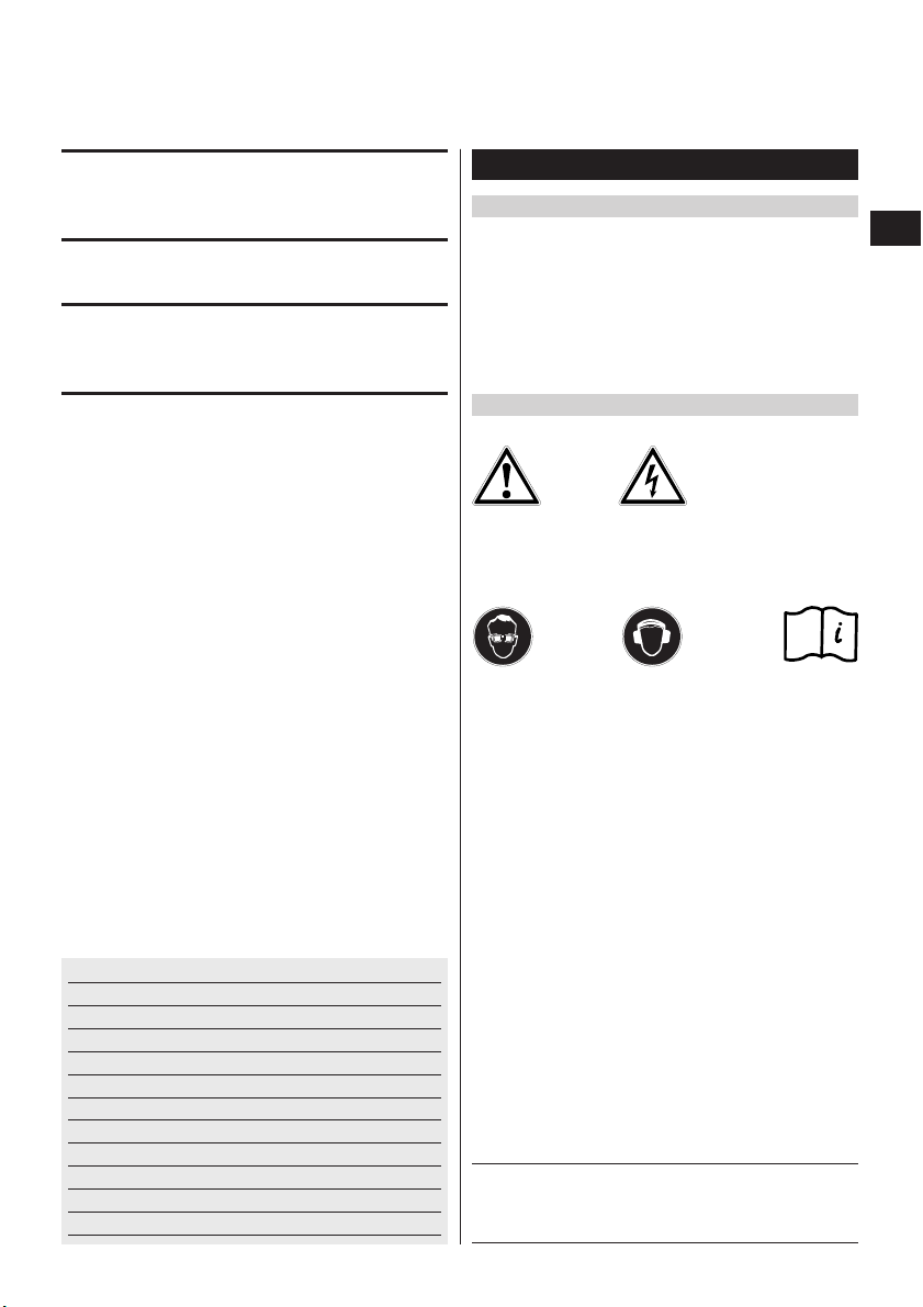
6.1 Fitting the scaffold hook
1. Unplug the supply cord from the electric socket.
2. Slide the scaffold hook over the tool from the front.
3. Rotate the scaffold hook into the desired position.
4. Secure the scaffold hook by tightening the knurled
screw.
-CAUTION-
Check that the scaffold hook is attached securely to the
tool.
6.2 Removing the protective sleeve
1. Unplug the supply cord from the electric socket.
2. Insert the tip of a screwdriver in the gap between the
tool and the protective sleeve. Pry the protective sleeve
away from the tool by turning the screwdriver.
3. Pull the protective sleeve off toward the front end of
the tool.
6.3 Use of a generator or transformer
This tool can be powered by a generator or by way of a
transformer connected to the construction site electric
supply when the following conditions and specifications
are fulfilled:
– Alternating current, power output at least 2600 W.
– The operating voltage must remain within +5% and
–15% of the rated voltage at all times.
– Permissible frequency: 50–60 Hz; never above 65 Hz.
– The equipment must be fitted with an automatic volt-
age regulator with starting compensation.
Never operate other tools or appliances from the
generator or transformer at the same time. Switching
other tools or appliances off and on can result in sudden
overvoltage or undervoltage which may cause damage
to the tool.
Wear ear
protection
Wear eye
protection
7. Operation
Use clamps or a vice to secure the workpiece.
The workpiece is thus held more securely than by
hand and both hands remain free to operate the
tool.
7.1 Setting forward / reverse rotation
The forward / reverse selector pushbutton can be used
to select the desired direction of rotation. An interlock
prevents operation of the pushbutton while the motor
is running.
– Pushbutton moved to the right (as seen with tool in
working position) = forwards rotation.
– Pushbutton moved to the left (as seen with tool in
working position) = reverse rotation.
7.2 Torque adjustment
1. Turn the torque adjusting ring to the desired torque
setting (positions 1–18, see section 2.2 for information on applications and screw types).
7.3 Switching on / off
1. Plug the supply cord into the electric socket.
-CAUTION-
● The screwdriving procedure may
cause the material to splinter.
● Splintering material may injure the
eyes.
● Wear eye protection.
Page 8

14
en
2. Press the control switch slowly. The speed of the tool
can thus be varied between 0 and maximum speed.
7.4 Lockbutton for sustained operation
Use of the lockbutton permits sustained operation (motor
running constantly) without need to maintain pressure
on the control switch.
7.4.1 Switching on in sustained operating mode
1. Press the control switch as far as it will go.
2. Press the lockbutton while maintaining pressure on
the control switch and then release the control switch.
7.4.2 Switching off when running in sustained mode
1. Press the control switch. The lockbutton returns to
its original position.
7.5 Fitting the depth gauge
1. Unplug the supply cord from the electric socket.
2. Insert the tip of a screwdriver in the gap between the
tool and the protective sleeve. Pry the protective sleeve
away from the tool by turning the screwdriver.
3. Pull the protective sleeve off toward the front end of
the tool.
4. Push the depth gauge onto the tool from the front.
7.6 Depth gauge adjustment
The depth gauge is used when driving screws with sealing
washers.
Use a depth gauge suitable for the applicable sealing
washer diameter (accessory).
The depth gauge can be adjusted to ensure correct compression of the sealing washer under the head of the
screw.
7.6.1 Adjusting the depth gauge
To decrease compression of sealing washer
1. Turn the depth gauge to the right (II).
To increase compression of sealing washer
1. Turn the depth gauge to the left. Compression of the
screw seal is increased (± 0.25 mm per click stop)
(III).
7.7 Removing the depth gauge
1. Pull the depth gauge off the tool toward the front.
7.8 Changing bits
The chuck is equipped with a
1
/4″ hexagon socket. This
size is standardized (DIN 3126/ ISO 1173).
1. Pull the depth gauge off the tool toward the front.
2. Pull the sleeve to the rear and hold it in this position.
3. The bit can then be pulled out or a different bit inserted.
4. Release the sleeve and allow it to return to its original position.
5. Refit the depth gauge to the tool.
7.9 Removing a previously driven screw
1. Pull the depth gauge off the tool toward the front.
2. Bring the forward / reverse pushbutton into the "reverse”
position.
3. The tool can now be used to remove the screw.
8. Care and maintenance
Unplug the supply cord from the mains socket.
8.1 Care of insert tools
Clean off dirt and dust deposits and protect your insert
tools from corrosion by wiping them from time to time
with an oil-soaked rag.
8.2 Care of the electric tool
The outer casing of the tool is made from impact-resistant plastic. Sections of the grip are made from an elastomer material.
Never operate the tool when the ventilation slots are
blocked. Clean the ventilation slots carefully using a dry
brush. Do not permit foreign objects to enter the interior
of the tool. Clean the outside of the tool at regular intervals
using a slightly damp cloth. Do not use a spray, steam
pressure cleaning equipment or running water for cleaning.
This may negatively affect the electrical safety of the tool.
Always keep the grip surfaces of the tool free from oil and
grease. Do not use cleaning agents which contain silicone.
8.3 Maintenance
Check all external parts of the tool for damage at regular
intervals and check that all controls operate faultlessly.
Do not operate the tool if parts are damaged or when the
controls do not function faultlessly. If necessary, your
electric tool should be repaired at a Hilti repair center.
Repairs to the electrical section of the tool may be carried out only by trained electrical specialists
8.4 Checks after care and maintenance
Check that the tool functions correctly (drive and remove
a screw) after carrying out care and maintenance.
Page 9

15
en
9. Disposal
Most of the materials from which Hilti electric tools are manufactured can be recycled. The materials must be
correctly separated before they can be recycled. In many countries, Hilti has already made arrangements for taking
back your old electric tools for recycling. Please ask your Hilti customer service department or Hilti representative for further information. Should you wish to return the electric tool yourself to a disposal facility for recycling,
proceed as follows: Dismantle the electric tool as far as possible without the need for special tools. Use absorbent
paper to wipe oily parts clean and to collect any grease that runs out (total quantity approx. 50 ml). This paper
should also be disposed of correctly. On no account should oil or grease be allowed to enter the waste water
system or to find its way into the ground.
The individual parts should be separated as follows:
Part / assembly Main material Recycling
Toolbox Plastic Plastics recycling
Gear housing Plastic Plastics recycling
Bearing plate Plastic Plastics recycling
Motor housing Plastic Plastics recycling
Grip cover Plastic Plastics recycling
Fan Plastic Plastics recycling
Motor (rotor and stator) Steel and copper Scrap metal
Supply cord Copper, elastomer Scrap metal
Gearing parts Steel / Aluminium Scrap metal
Screws, small parts Steel Scrap metal
10. Warranty
Hilti warrants that the tool supplied is free of defects in
material and workmanship. This warranty is valid as long
as the tool is operated and handled correctly, cleaned
and serviced properly and in accordance with the Hilti
operating instructions, all warranty claims are made within 12 months (unless other mandatory national regulations prescribe a longer minimum period) from the date
of the sale (invoice date), and the technical system is
maintained. This means that only original Hilti consumables, components and spare parts may be used in the
tool.
This warranty provides the free-of-charge repair or replacement of defective parts only. Parts requiring repair or
replacement as a result of normal wear and tear are not
covered by this warranty.
Additional claims are excluded, unless mandatory
national rules prohibit such exclusion. In particular,
Hilti is not obligated for direct, indirect, incidental or
consequential damages, losses or expenses in connection with, or by reason of, the use of, or inability to
use the tool for any purpose. Implied warranties of
merchantability or fitness for a particular purpose are
specifically excluded.
Send the tool and/or related parts immediately upon dis-
covery of a defect to the local Hilti marketing organisation for repair or replacement.
This constitutes Hilti’s entire obligation with regard to
warranty and supersedes all prior or contemporaneous
comments and oral or written agreements concerning
warranties.
Page 10

16
en
11. EC declaration of conformity
We declare, on our sole responsibility, that this product
complies with the following directives and standards:
73/23/EWG, 98/37/EG, 89/336/EWG, EN 50144-1,
EN 50144-2-2, EN 55014-1, EN 55014-2, EN 61000-3-2,
EN 61000-3-3.
Designation: Electric screwdriver
Type: ST1800
Year of design: 2003
Hilti Corporation
Dr. Joachim Schneider Schütz Ronald
Head Business Unit Head Development
Cutting and Sanding / Screw Fastening Screw Fastening
May 2003 May 2003
 Loading...