

Page 1

AG125-S/AG125-SE
*282138*
282138
Bedienungsanleitung 1– 12
Operating instructions 13–24
Mode d’emploi 25–36
Istruzioni d’uso 37–48
Gebruiksaanwijzing 49–60
Manual de instruções 61–72
Manual de instrucciones 73–84
Brugsanvisning 85–96
Käyttöohje 97–108
Bruksanvisning 109–120
Bruksanvisning 121–132
ΟΟδδηηγγιιεεςς χχρρηησσεεωως
ς
133–146
Ръководство за
обслужване
147–158
Upute za uporabu
159–170
Instrukcja obsługi
171–184
Инструкция по
зксплуатации
185–197
Návod na obsluhu
199–210
Návod k obsluze
211–222
Használati utasítás
223–234
Kasutusjuhend
235–246
Lietoßanas pamåcîba
247–258
Instrukcija
259–270
de
en
fr
it
nl
pt
es
da
fi
no
sv
el
bg
hr
pl
ru
sk
cs
hu
et
lv
lt
Printed: 07.07.2013 | Doc-Nr: PUB / 5069435 / 000 / 00
Page 2
4
5
6
7
8
9
10
1
13
2
3
12
11
Kwik Lock
6
1
Printed: 07.07.2013 | Doc-Nr: PUB / 5069435 / 000 / 00
Page 3
2
3
4
5
6
1
2
3
1
5
4
6
7
3
1
2b
2a
1
3
4
6
5
2
1
5
3,7
4,6
Printed: 07.07.2013 | Doc-Nr: PUB / 5069435 / 000 / 00
Page 4
7
8 9
D
C
1
2
5
S
D
C
1
2
5
S
Printed: 07.07.2013 | Doc-Nr: PUB / 5069435 / 000 / 00
Page 5

1
AG 1 25-S/-SE
Diamant-Trenngerät
Lesen Sie die Bedienungsanleitung vor Inbetriebnahme
unbedingt durch.
Bewahren Sie diese Bedienungsanleitung immer
beim Gerät auf.
Geben Sie das Gerät nur mit Bedienungsanleitung an
andere Personen weiter.
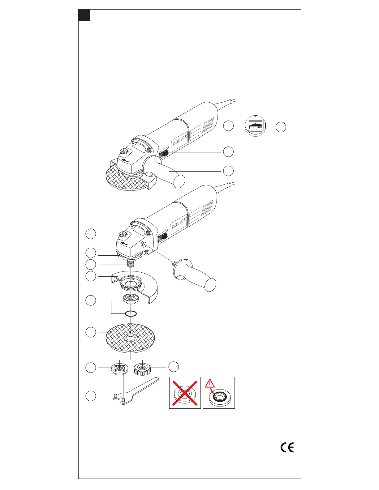
Bedienungs- und Anzeigeelemente
햲 Lüftungsschlitze 햹 Spannflansch mit O-Ring
햳 Ein-/Aus-Schalter 햺 Trennscheibe / Schleifscheibe
햴 Seitenhandgriff 햻 Spannmutter
햵 Spindel-Arretierknopf 햽 Schnellspannmutter «Kwik-Lock»
햶 Hauben-Entriegelungsknopf 햾 Stirnlochschlüssel
햷 Schleifspindel 햿 Stellrad für Drehzahlvorwahl (Typ SE)
햸 Schutzhaube
Inhalt Seite Inhalt Seite
1. Allgemeine Hinweise 1 7. Bedienung 10
2. Beschreibung 2 8. Pflege und Instandhaltung 11
3. Werkzeuge und Zubehör 2 9. Fehlersuche 11
4. Technische Daten 3 10. Entsorgung 11
5. Sicherheitshinweise 4 11. Garantie 12
6. Inbetriebnahme 7 12. EG-Konformitätserklärung 12
1. Allgemeine Hinweise
1.1 Signalwort für die Gefahr
-VORSICHT-
Für eine möglicherweise gefährliche Situation, die zu leichten Körperverletzungen
oder zu Sachschaden führen könnte.
-HINWEIS-
Für Anwendungshinweise und andere nützliche Informationen.
1.2 Piktogramme
Warnzeichen Symbole
Warnung
vor gefährlicher
elektrischer
Spannung
Warnung
vor heisser
Oberfläche
Vor Benutzung
Bedienungsan-
leitung
lesen.
Warnung
vor allgemeiner
Gefahr
Abfälle der
Wiederverwertung
zuführen
Printed: 07.07.2013 | Doc-Nr: PUB / 5069435 / 000 / 00
Page 6

2
Gebotszeichen
Schutzhelm
benutzen
Leichten
Atemschutz
benutzen
Gehörschutz
benutzen
Schutz-
handschuhe
benutzen
Augenschutz
benutzen
Die Zahlen verweisen jeweils auf Abbildungen. Die Abbildungen zum Text finden
Sie auf den ausklappbaren Umschlagseiten. Halten Sie diese beim Studium der Anleitung geöffnet.
Im Text dieser Bedienungsanleitung bezeichnet «das Gerät» immer das DiamantTrenngerät AG125-S/-SE.
Ort der Identifizierungsdetails auf dem Gerät
Die Typenbezeichnung und die Serienkennzeichnung sind auf dem Typenschild Ihres
Geräts angebracht. Übertragen Sie diese Angaben in Ihre Bedienungsanleitung und
beziehen Sie sich bei Anfragen an unsere Vertretung oder Servicestelle immer auf
diese Angaben.
Typ:
Serien Nr.:
2. Beschreibung
2.1 Elektronische Regelung und Steuerung
2.1.1 Anlaufstrom-Begrenzung
Der Einschaltstrom des Geräts beträgt ein Mehrfaches des Nennstroms. Durch die
elektronische Anlaufstrombegrenzung wird der Einschaltstrom so weit reduziert, dass
die Netzsicherung nicht anspricht. Ein ruckartiges Anlaufen des Geräts wir dadurch
vermieden.
2.1.2 Konstantelektronik
Die elektronische Drehzahlregulierung hält die Drehzahl zwischen Leerlauf und Last
nahezu konstant. Das bedeutet optimale Materialbearbeitung durch konstante Arbeitsdrehzahl.
2.2 Geräteschutz
2.2.1 Temperaturabhängiger Motorschutz
Der temperaturabhängige Motorschutz überwacht Stromaufnahme sowie Motorerwärmung und schützt so das Gerät vor Überhitzung.
Bei Überlastung des Motors während des Arbeitens mit dem Gerät bleibt der Motor
stehen und läuft erst wieder an, nachdem der Anpressdruck, beispielsweise beim
Schleifen, vermindert wird.
Die zulässige Überbelastung des Geräts ist dabei keine bestimmte vorgegebene Grösse, sondern jeweils abhängig von der Motorentemperatur.
Tritt Überlastung auf, müssen Sie das Gerät entlasten und ca. 30 Sekunden in Leerlaufdrehzahl betreiben.
3. Werkzeuge und Zubehör
Hilti Abrasiv Trenn- und Schleifscheiben
(∅ max. 125 mm, Drehzahl max. 11000 U/min, Umfanggeschwindigkeit max. 80 m/sec
AC-D Universal Premium Trennen
AC-D Universal Super Premium Trennen
Printed: 07.07.2013 | Doc-Nr: PUB / 5069435 / 000 / 00
Page 7

3
AC-D INOX Trennen
AG-D Universal Premium Schleifen
AG-D Universal Super Premium Schleifen
AF-D Fächerscheiben Schleifen
Fremdprodukte
(∅ max. 125 mm, Drehzahl max. 11000 U/min, Umfanggeschwindigkeit max. 80 m/sec
Drahtbürsten
Schleiftöpfe, Gummiteller
Weiteres Zubehör
Schnellspannmutter Kwik-Lock
Staubhaube für Schleifarbeiten DG125-EX
Schutzhaube mit Führungsschlitten
Staubabsaughaube für Trennarbeiten DC125-EX
Staubsauger TDA-VC40/60
3.1 Schleif-/ Trennscheibe mit Schnellspannmutter Kwik-Lock
Anstelle der Spannmutter kann das Kwik-Lock verwendet werden. Damit lassen sich
Trennscheiben ohne Werkzeug wechseln.
-HINWEIS-
Für Schleiftöpfe, Bürsten, Gummi-Schleifteller , Tuck pointing-Scheiben und DiamantTopfscheiben kann Kwik-Lock nicht eingesetzt werden.
3.2 Staubhaube für Schleifarbeiten
Das Gerät ist nur bedingt für gelegentliches Schleifen von mineralischen Untergründen mit Diamant-Topfscheiben geeignet.
-HINWEIS-
Diese Anwendung darf nur mit entsprechender Staubhaube und Staubsauger ausgeführt werden.
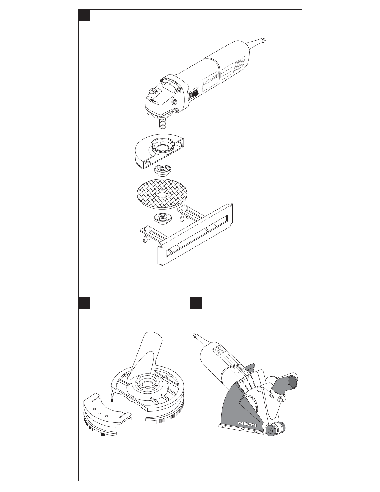
3.3 Schutzhaube mit Führungsschlitten
Trennarbeiten sollten mit einem Führungsschlitten ausgeführt werden.
3.4 Staubabsaughaube
Generell wird empfohlen beim Schlitzen oder T rennen von Beton oder Stein eine Staubabsaughaube mit einem geeigneten Hilti Staubsauger zu verwenden.
Diese dient dem Schutz des Benutzers und erhöht die Lebensdauer des Geräts und
des Werkzeugs.
4. Technische Daten
Gerät AG125-S / AG125-SE
Nennspannung 110 V 230 V 240 V
Nennstrom 8,8 A 4,5 A 4,3 A
Leistungsaufnahme 1020 W
Leistungsabgabe 550 W 600 W 600 W
Netzfrequenz 50 Hz
Leerlaufdrehzahl AG125-S:
E 11000 U/min.
AG125-SE: 2800–11000 U/min.
Gewinde-Antriebsspindel M 14
Trennscheiben ∅ max. 125 mm
Gewicht ca. (ohne Zubehör) 1,6 kg
Schutzisoliert (nach EN 50144) Schutzklasse II Z
Störfestigkeit Nach EN 55014-2
Das Gerät ist funk- und fernsehentstört Nach EN 55014-1
Printed: 07.07.2013 | Doc-Nr: PUB / 5069435 / 000 / 00
Page 8

4
Geräusch- und Vibrationsinformation (gemessen nach EN 50144):
Typischer A-bewerteter
Schalleistungspegel (LwA): = 101 dB (A)
Typischer A-bewerteter
Emissions-Schalldruckpegel (LpA): = 88 dB (A)
Gehörschutz benutzen!
Typische bewertete Vibration an den = 5,0 m/s
2
(Standard Handgriff)
Handgriffen: = 3,5m/s2(vibrationsreduzierter Handgriff)
TechnischeÄnderungen vorbehalten!
5. Sicherheitshinweise
5.1 Grundlegende Sicherheitsvermerke
Neben den sicherheitstechnischen Hinweisen in den einzelnen Kapiteln dieser Bedienungsanleitung sind folgende Bestimmungen jederzeit strikt zu beachten.
5.2 Bestimmungsgemässe Verwendung
Das Gerät ist bestimmt zum Trennen, Schruppen und Bürsten von Metall- und Steinwerkstoffen ohne Verwendung von Wasser. Zum Trennen von Stein ist ein Führungsschlitten vorgeschrieben.
Das Arbeitsumfeld kann sein: Baustelle, Werkstatt, Renovierungen, Umbau und Neubau.
Der Betrieb darf nur mit der auf dem Typenschild angegebenen Netzspannung und frequenz erfolgen.
● Verwenden Sie nur kunstharzgebundene faserstoffarmierte Schrupp- oder Trennscheiben mit einer zulässigen Umfanggeschwindigkeit von 80 m/sec sowie
Diamanttrennscheiben mit einer zulässigen Umfanggeschwindigkeit von 80 m/sec.
● Das Gerät darf nur für Trockenschliff/-schnitt verwendet werden.
● Asbesthaltige Materialien dürfen nicht bearbeitet werden.
● Beim Schleifen von Stein muss eine Staubabsaugung mit Steinstaubfilter, z. B. Hil-
ti Staubsauger TDA-VC 40/60 verwendet werden.
● Manipulationen oder Veränderungen am Gerät sind nicht erlaubt.
● Benutzen Sie, um Verletzungsgefahren zu vermeiden, nur original Hilti Zubehör
und Zusatzgeräte.
● Beachten Sie die Angaben zu Betrieb, Pflege und Instandhaltung in der Bedienungsanleitung.
● Vom Gerät und seinen Hilfsmitteln können Gefahren ausgehen, wenn sie von unausgebildetem Personal unsachgemäss behandelt oder nicht bestimmungsgemäss verwendet werden.
5.3 Sachgemässe Einrichtung der Arbeitsplätze
● Sorgen Sie für eine gute Beleuchtung.
● Sorgen Sie für gute Belüftung des Arbeitsplatzes.
● Halten Sie das Arbeitsumfeld frei von Gegenständen an denen Sie sich verletzen
könnten.
● Halten Sie beim Arbeiten andere Personen, insbesondere Kinder, vom Wirkungsbereich fern.
● Vermeiden Sie eine ungünstige Körperhaltung.
● Beim Schleifen kann Funkenflug entstehen. Achten Sie darauf, dass keine Perso-
nen gefährdet werden. Wegen Brandgefahr dürfen sich keine brennbaren Materialien in der Nähe (Funkenflugbereich) befinden.
● Beachten Sie die Drehrichtung! Halten Sie das Gerät immer so, dass Funken und
Schleifstaub vom Körper wegfliegen.
● Tragen Sie rutschfestes Schuhwerk und sorgen Sie jederzeit für sicheren Stand.
Printed: 07.07.2013 | Doc-Nr: PUB / 5069435 / 000 / 00
Page 9

5
● Bei Arbeiten im Freien sind Gummihandschuhe empfehlenswert.
● Tragen Sie geeignete Arbeitskleidung. Tragen Sie keine weiten Kleider, lose lange
Haare und Schmuck, sie könnten von beweglichen T eilen erfasst werden.
● Führen Sie, um eine Sturzgefahr beim Arbeiten zu vermeiden, das Netz- das Verlängerungskabel und den Absaugschlauch immer nach hinten vom Gerät weg.
● Verdeckt liegende elektrische Leitungen, Gas- und Wasserrohre stellen eine ernsthafte Gefährdung dar, wenn sie beim Arbeiten beschädigt werden. Prüfen Sie daher
den Arbeitsbereich vorher z.B. mit einem Metallsuchgerät ab. Vermeiden Sie Körperberührung mit geerdeten Teilen, z.B. Rohren und Heizkörpern. Aussenliegende
Metallteile am Gerät können spannungsführend werden, wenn Sie z.B. versehentlich
eine Stromleitung beschädigt haben.
● Befestigen Sie lose Werkstücke mit einer Spannvorrichtung oder einem Schraubstock.
5.4 Allgemeine Sicherheitsmassnahmen
● Betreiben Sie das Gerät nur bestimmungsgemäss und in einwandfreiem Zustand.
● Setzen Sie das Gerät nicht Niederschlägen aus, benutzen Sie es nicht in feuchter
oder nasser Umgebung sowie in der Nähe von brennbaren Flüssigkeiten oder Gasen.
● Lassen Sie ein Gerät nie unbeaufsichtigt.
● Verwenden Sie nur Schleifwerkzeuge deren zulässige Drehzahl mindestens so hoch
ist, wie die höchste Leerlaufdrehzahl des Geräts.
● Vergewissern Sie sich, dass die Masse der Scheibe zum Gerät passen.
● Schleifscheiben müssen sorgsam nach den Anweisungen des Herstellers aufbe-
wahrt und gehandhabt werden.
● Vergewissern Sie sich, dass die Schleifwerkzeuge nach den Anweisungen des Herstellers angebracht sind.
● Verwenden Sie keine getrennten Reduzierbuchsen oder Adapter , um Schleifscheiben
mit grossem Loch passend zu machen.
● Vergewissern Sie sich bei Schleifwerkzeugen mit Gewindeeinsatz, dass das Gewinde lang genug ist, um die Spindellänge aufzunehmen.
● Verwenden Sie keine Trennschleifscheiben zum Schruppschleifen.
● Beschädigte, unrunde bzw. vibrierende Schleifwerkzeuge dürfen nicht verwendet
werden.
● Bei allen Arbeiten muss der Seitengriff montiert sein.
● Das Gerät darf nur handgeführt eingesetzt werden.
● Halten Sie das Gerät immer mit beiden Händen fest.
● Halten Sie den Seitenhandgriff am äusseren Ende fest.
● Halten Sie den Handgriff trocken, sauber und frei von Öl und Fett.
● Die Schutzhaube darf nicht demontiert werden.
● Schützen Sie die Schleifwerkzeuge vor Stoss, Schlag und Fett.
● Überlasten Sie Ihr Gerät nicht. Sie arbeiten besser und sicherer im angegebenen
Leistungsbereich.
● Nicht in Gebrauch stehende Geräte müssen, an einem trockenen, hochgelegenen
oder abgeschlossenen Ort ausserhalb der Reichweite von Kindern, aufbewahrt werden.
● Vermeiden Sie einen unbeabsichtigten Anlauf. Tragen Sie das Gerät nicht mit dem
Finger am Ein-/Ausschalter.
● Ziehen Sie bei Nichtgebrauch des Geräts (z.B. während einer Arbeitspause), vor
Pflege, Instandhaltung und Wechsel von Werkzeugen, den Netzstecker immer aus
der Steckdose.
● Pflegen Sie Ihre Werkzeuge mit Sorgfalt. Halten Sie die Werkzeuge scharf und sauber , um besser und sicherer arbeiten zu können. Befolgen Sie die Wartungsvorschriften
und die Hinweise über den Werkzeugwechsel.
● Überprüfen Sie , ob bewegliche Teile einwandfrei funktionieren und nicht klemmen, oder ob T eile beschädigt sind. Sämtliche T eile müssen richtig montiert sein und
alle Bedingungen erfüllen, um einen einwandfreien Betrieb des Geräts zu gewährleisten.
● -VORSICHT- Das Gerät läuft nach dem Ausschalten nach.
● Bremsen Sie das nachlaufende Schleifwerkzeug nicht durch seitliches Gegen-
drücken ab.
Printed: 07.07.2013 | Doc-Nr: PUB / 5069435 / 000 / 00
Page 10

6
● Neue Schleifwerkzeuge bei max. Leerlaufdrehzahl mindestens 30 Sekunden zur
Probe laufen lassen. Sofort anhalten, wenn beträchtliche Schwingungen auftreten
oder wenn andere Mängel festgestellt werden. Wenn dieser Zustand eintritt, überprüfen Sie das Gerät, um die Ursache zu ermitteln.
● Vor weiterem Gebrauch des Geräts sollten Schutzvorrichtungen oder leicht beschädigte Teile sorgfältig auf ihre einwandfreie und bestimmungsgemässe Funktion überprüft werden. Beschädigte Schutzvorrichtungen und Teile sollten sachgemäss durch
eine anerkannte Fachwerkstatt repariert oder ausgewechselt werden, soweit nichts
anderes in der Bedienungsanleitung angegeben ist.
● Vergewissern Sie sich vor dem Einstecken des Netzsteckers in die Steckdose, dass
das Gerät ausgeschaltet ist.
5.4.1 Mechanisch
● Lassen Sie keine Werkzeugschlüssel stecken. Überprüfen Sie vor dem Einschalten, dass Schlüssel und Einstellwerkzeuge entfernt sind.
● Befolgen Sie die Hinweis für die Pflege, Instandhaltung und den rechtzeitigen Werkzeugtausch.
● Stellen Sie sicher, dass die Werkzeuge das zum Gerät passende Aufnahmesystem
aufweisen und ordnungsgemäss in der Werkzeugaufnahme verriegelt sind.
● Bei Montage des Werkzeugs den Drehrichtungspfeil beachten.
5.4.2 Elektrisch
● Prüfen Sie das Gerät inkl. Netz- und Verlängerungskabel sowie die Steckverbindungen auf ordnungsgemässen Zustand. Betreiben Sie das Gerät nicht, wenn Beschädigungen vorliegen, das Gerät nicht komplett ist oder Bedienungselemente sich nicht
einwandfrei betätigen lassen.
● Wird bei der Arbeit das Netz- oder Verlägerungskabel beschädigt, dürfen Sie das
Kabel nicht berühren. Ziehen Sie den Netzstecker aus der Steckdose.
● Beschädigte Schalter müssen beim Hilti Service ersetzt werden. Benutzen Sie kein
Gerät, bei dem sich der Schalter nicht ein- und ausschalten lässt.
● Lassen Sie Ihr Gerät durch eine Elektrofachkraft (Hilti Service) reparieren.
● Tragen Sie das Gerät niemals am Kabel.
● Ziehen Sie den Stecker nicht am Kabel aus der Steckdose.
● Schützen Sie das Kabel vor Hitze, Öl und scharfen Kanten.
● Verwenden Sie im Freien nur dafür zugelassene und entsprechend gekennzeich-
nete Verlängerungskabel.
● Bei Stromunterbruch: Gerät ausschalten, Stecker herausziehen.
● Verlängerungskabel mit Mehrfachsteckdosen und gleichzeitigem Betrieb von meh-
reren Geräten sind zu vermeiden.
● Verwenden Sie, um eine Unfallgefahr zu vermeiden, nur Originalersatzteile.
● Betreiben Sie das Gerät nie in verschmutztem oder nassem Zustand. An der Gerä-
teoberfläche haftender Staub oder Feuchtigkeit verschlechtert die Griffigkeit und kann
unter ungünstigen Bedingungen zu elektrischem Schlag führen.
5.4.3 Thermisch
Warnung vor Schutzhandschuhe
heisser Oberfläche benutzen
● Das Werkzeug kann durch den Einsatz heiss werden. Für den Werkzeugwechsel
sollten Sie darum Schutzhandschuhe benutzen.
5.4.4 Stäube
Leichten Atemschutz benutzen
● Wird das Gerät ohne Staubabsaugung betrieben, müssen Sie bei stauberzeugenden Arbeiten einen leichten Atemschutz benutzen.
Printed: 07.07.2013 | Doc-Nr: PUB / 5069435 / 000 / 00
Page 11

7
● Sorgen Sie dafür, dass bei staubigen Arbeiten die Lüftungsöffnungen frei sind. Falls
es erforderlich werden sollte, den Staub zu entfernen, trennen Sie zuerst das Gerät
vom Stromversorgungsnetz (verwenden Sie nichtmetallische Objekte) und vermeiden Sie das Beschädigen innerer Teile.
● Der Betreiber hat sicherzustellen, dass der schädliche Schleifstaub nach den nationalen und regionalen Vorschriften entsorgt wird.
● Beim Bearbeiten von leitfähigen Materialien kann sich leitfähiger Staub im Inneren
des Geräts ansammeln, die Isolation überbrücken und einen elektrischen Schlag verursachen. Deshalb müssen die verwendeten Geräte in engen Zeitintervallen von Fachkräften oder im Hilti-Service hinsichtlich Isolationsfestigkeit oder Ansammlung von
leitfähigen Stäuben oder sonstigen leitfähigen Ablagerungen überprüft werden.
● Beim Schleifen muss ein Baustaubsauger mit für die jeweilige Bearbeitung entsprechenden Filtern eingesetzt werden.
● Klären Sie vor Beginn der Arbeit die Gefahrenklasse des beim Schleifen entstehenden Staubguts ab. Verwenden Sie immer Augen- und Gehörschutz. Andere Personenschutzausrüstungen wie Staubmaske, Handschuhe, Schürze und Helm sollten, wenn notwendig, getragen werden. Für die Bewertung, ob eine Gesichts- oder
Staubmaske benötigt wird, sollten die gefährdenden Eigenschaften sowohl von dem
zu schleifenden Werkstoff als auch von möglichen Anstrichen und Oberflächenbeschichtungen beachtet werden. Im Zweifel ist die Schutzausrüstung zu tragen. Verwenden Sie zur Arbeit mit dem Gerät einen Baustaubsauger mit einer offiziell zugelassenen Schutzklassifizierung, die Ihren lokalen Staubschutzbestimmungen entsprechen.
5.5 Anforderung an den Benutzer
● Das Gerät ist für den professionellen Benutzer bestimmt.
● Das Gerät darf nur von autorisiertem, eingewiesenem Personal bedient, gewartet
und instand gehalten werden. Dieses Personal muss speziell über die auftretenden
Gefahren unterrichtet sein.
● Arbeiten Sie stets konzentriert. Gehen Sie überlegt vor und verwenden Sie das
Gerät nicht, wenn Sie unkonzentriert sind.
5.6 Persönliche Schutzausrüstung
Der Benutzer und die sich in der Nähe aufhaltenden Personen müssen während dem
Einsatz des Geräts eine geeignete Schutzbrille, Schutzhelm, Gehörschutz, Schutzhandschuhe und wenn Sie keine Staubabsaugung verwenden, einen leichten Atemschutz benutzen.
5.7 Schutzeinrichtung
Setzen Sie das Gerät nie ohne Schutzhaube ein.
6. Inbetriebnahme
Schutzhelm
benutzen
Leichten
Atemschutz
benutzen
Gehörschutz
benutzen
Schutz-
handschuhe
benutzen
Augenschutz
benutzen
-VORSICHT-
■ Das Werkzeug kann durch den Einsatz heiss werden.
■ Sie können sich die Hände verbrennen.
■ Benutzen Sie für den Werkzeugwechsel Schutzhandschuhe.
Printed: 07.07.2013 | Doc-Nr: PUB / 5069435 / 000 / 00
Page 12

8
6.1 Einsatz von Verlängerungskabel
Verwenden Sie nur für den Einsatzbereich zugelassene Verlängerungskabel mit ausreichendem Querschnitt.
Empfohlene Mindestquerschnitte und max. Kabellängen:
Netz- Leiterquerschnitt
spannung 1,5 mm22,0 mm22,5 mm23,3 mm2AWG AWG
100 V – 30 m – 50 m – –
110–120 V 20 m 30 m 40 m 50 m 75 ft 125 ft
220–240 V 50 m – 100 m – – –
Verwenden Sie keine Verlängerungskabel mit 1,25 mm
2
und 16 AWG Leiterquerschnitt.
6.2 Einsatz eines Generators oder Transformators
Dieses Gerät kann ab einem Generator oder bauseitigen Transformator betrieben werden, wenn die folgenden Bedingungen eingehalten sind:
– Wechselspannung, Abgabeleistung mindestens 2600W.
– Die Betriebsspannung muss jederzeit innerhalb + 5% und –15% zur Nennspan-
nung sein.
– Die Frequenz 50–60 Hz; niemals über 65 Hz.
– Automatische Spannungsregler mit Anlaufverstärkung.
Betreiben Sie am Generator / T ransformator keinesfalls gleichzeitig andere Geräte.
Das Ein- und Ausschalten anderer Geräte kann Unterspannungs- und/oder Überspannungsspitzen verursachen, die das Gerät beschädigen kann.
6.3 Seitenhandgriff montieren
Bei allen Arbeiten muss der Seitenhandgriff montiert sein. Der Seitenhandgriff kann
an der linken oder rechten Geräteseite eingeschraubt werden.
6.4 Schutzhaube
-HINWEIS-
Bei allen Arbeiten muss die Schutzhaube montiert sein.
Achten Sie darauf, dass die geschlossene Seite der Schutzhaube stets zum Körper
des Benutzers gerichtet ist.
Die Stellung der Schutzhaube kann den jeweiligen Erfordernissen des Arbeitsgangs
angepasst werden.
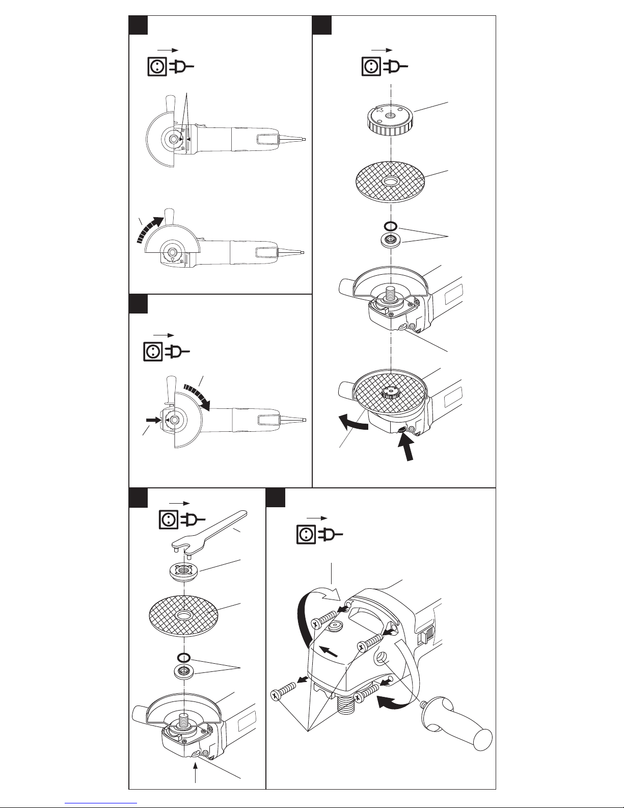
6.4.1 Schutzhaube montieren
Die Schutzhaube besitzt Codiernocken, welche Sicherstellen dass nur eine zum Gerät
passende Schutzhaube montiert werden kann.
Die Schutzhaube läuft mit ihren Codiernocken in der Führungsnut am Spindelhals
des Geräts.
Das Gerät hat eine Bajonett-Schnellspannung für die Schutzhaube.
1. Ziehen Sie den Netzstecker aus der Steckdose.
2. Setzen Sie die Schutzhaube so auf den Spindelhals, dass die beiden Dreieck-Mar-
kierungen an der Schutzhaube und am Gerät sich gegenüberstehen.
3. Drücken Sie die Schutzhaube gegen die Federkraft auf den Spindelhals und dre-
hen Sie sie bis sie einrastet.
6.4.2 Schutzhaube verstellen
1. Ziehen Sie den Netzstecker aus der Steckdose.
2. Drücken Sie den Entriegelungsknopf und drehen Sie die Schutzhaube in die
gewünschte Position.
6.4.3 Schutzhaube demontieren
1. Ziehen Sie den Netzstecker aus der Steckdose.
2. Drücken Sie den Entriegelungsknopf und drehen Sie die Schutzhaube bis die bei-
den Dreieck-Markierungen an der Schutzhaube und am Gerät sich gegenüberstehen.
3. Heben Sie die Schutzhaube ab.
6.5 Schleif-/ Trennscheibe montieren
Verwenden Sie nur Schleifwerkzeuge deren zulässige Drehzahl mindestens so hoch
ist, wie die höchste Leerlaufdrehzahl des Geräts.
Printed: 07.07.2013 | Doc-Nr: PUB / 5069435 / 000 / 00
Page 13

9
Beschädigte, unrunde bzw. vibrierende Schleifwerkzeuge dürfen nicht verwendet
werden.
1. Ziehen Sie den Netzstecker aus der Steckdose.
2. Setzen Sie den Spannflansch auf die Schleifspindel.
-HINWEIS-
Im Spannflansch ist ein O-Ring eingesetzt. Fehlt dieser O-Ring oder ist er beschädigt, muss er ersetzt werden.
3. Setzen Sie die Diamanttrennscheibe, Trennscheibe oder Schleifscheibe auf.
4. Schrauben Sie die Spannmutter fest.
5. Drücken Sie den Spindel-Arretierknopf und halten Sie ihn gedrückt.
-HINWEIS-
Der Spindel-Arretierknopf darf nur bei stillstehender Schleifspindel betätigt werden.
6. Ziehen Sie mit dem Strinlochschlüssel die Spannmutter fest und lassen Sie ansch-
liessend den Spindel-Arretierknopf los.
6.6 Schleif-/ Trennscheibe mit Schnellspannmutter Kwik-Lock
Anstelle der Spannmutter kann das Kwik-Lock verwendet werden. Damit lassen sich
Trennscheiben ohne Werkzeug wechseln.
-HINWEIS-
Für Schleiftöpfe, Bürsten, Gummi-Schleifteller , Tuck pointing-Scheiben und DiamantTopfscheiben kann Kwik-Lock nicht eingesetzt werden.
6.6.1 Schleif-/ Trennscheibe mit Schnellspannmutter Kwik-Lock montieren
Der Pfeil auf der Oberseite muss sich innerhalb der Indexmarke befinden. Wird die
Schnellspannmutter angezogen, ohne dass der Pfeil sich innerhalb der Indexmarke
befindet, lässt sie sich nicht mehr von Hand öffnen. In diesem Fall die Schnellspannmutter mit dem Stirnlochschlüssel lösen (Nicht mit einer Rohrzange).
1. Ziehen Sie den Netzstecker aus der Steckdose.
2. Reinigen Sie den Spannflansch und die Schnellspannmutter.
3. Setzen Sie den Spannflansch auf die Schleifspindel.
-HINWEIS-
Im Spannflansch ist ein O-Ring eingesetzt. Fehlt dieser O-Ring oder ist er beschä-
digt, muss er ersetzt werden.
4. Setzen Sie die Diamanttrennscheibe, Trennscheibe oder Schleifscheibe auf.
5. Schrauben Sie die Schnellspannmutter (Beschriftung im aufgeschraubten Zustand
sichtbar) bis zum Aufsitzen auf der Schleifscheibe auf.
6. Drücken Sie den Spindel-Arretierknopf und halten Sie ihn gedrückt.
-HINWEIS-
Der Spindel-Arretierknopf darf nur bei stillstehender Schleifspindel betätigt wer-
den.
7. Drehen Sie die Schleifscheibe mit der Hand im Uhrzeigersinn kräftig weiter bis die
Schnellspannmutter fest angezogen ist.
6.6.2 Schleif-/ Trennscheibe mit Schnellspannmutter Kwik-Lock demontieren
1. Ziehen Sie den Netzstecker aus der Steckdose.
2. Lösen Sie die Schnellspannmutter durch drehen des Rändelrings im Gegenuhr-
zeigersinn (Lösen Sie eine festsitzende Schnellspannmutter mit dem Strinlochschlüssel. Verwenden Sie keine Rohrzange).
6.7 Getriebekopf drehen
Um in jeder Lage sicher und ermüdungsfrei arbeiten zu können, (z.B. Ein-/AusSchalter nach oben) lässt sich der Getriebekopf viermal um 90º verstellen.
1. Ziehen Sie den Netzstecker aus der Steckdose.
2. Reinigen Sie das Gerät.
3. Entfernen Sie den Seitenhandgriff vom Gerät.
4. Entfernen Sie die vier Schrauben am Getriebekopf.
5. Drehen Sie den Getriebekopf, ohne ihn nach vorne vom Gerät zu ziehen, in die
gewünschte Position.
6. Befestigen Sie den Getriebekopf mit den vier Schrauben.
7. Montieren Sie den Seitenhandgriff.
Printed: 07.07.2013 | Doc-Nr: PUB / 5069435 / 000 / 00
Page 14

10
7. Bedienung
● Die Netzspannung muss mit den Angaben auf dem Typenschild des Geräts übereinstimmen. Mit 230 V gekennzeichnete Geräte können mit 220 V betrieben werden.
● Verwenden Sie das Gerät immer mit dem Seitenhandgriff.
● Befestigen Sie lose Werkstücke mit einer Spannvorrichtung oder einem Schraub-
stock.
7.1 Statikhinweis
Schlitze in tragenden Wänden unterliegen der Norm DIN 1053 Teil 1 oder länderspezifischen Festlegungen.
Diese Vorschriften sind unbedingt einzuhalten. Vor Arbeitsbeginn den verantwortlichen Statiker, Architekten oder die zuständige Bauleitung befragen.
-VORSICHT-
■ Das Gerät und der Schleifvorgang erzeugen Schall.
■ Zu starker Schall kann das Gehör schädigen.
■ Benutzen Sie einen Gehörschutz.
-VORSICHT-
■ Durch den Schleifvorgang kann Material absplittern.
■ Abgesplittertes Material kann Körper und Augen verletzen.
■ Benutzen Sie einen Augenschutz, Schutzhandschuhe und wenn
Sie keine Staubabsaugung verwenden, einen leichten Atemschutz.
7.2 Betrieb
-HINWEIS-
Neue Schleifwerkzeuge bei max. Leerlaufdrehzahl mindestens 30 Sekunden zur Probe laufen lassen.
-VORSICHT-
Verwenden Sie niemals Trennschleifscheiben zum Schruppen.
7.3 Drehzahlvorwahl (Typ: AG125-SE)
Untergrund Anwendung Werkzeug Drehzahlvorwahl
Kunststoff Polieren Lammfellhaube 1
Feinschliff Filzpolierhaube 1
Metall Feinschliff Schwabbelscheibe 1
Farbe entfernen Schleifblatt 2–3
Holz, Metall Bürsten, Topfbürste,
Entrosten Schleifblatt 3
Metall, Stein Schleifen Schleifscheibe 4–6
Metall Schruppen Schruppscheibe 6
Stein* Trennen* Trennscheibe und Führungschlitten 6
* Trennen von Gestein ist nur mit Führungschlitten zulässig (Zubehör)
Printed: 07.07.2013 | Doc-Nr: PUB / 5069435 / 000 / 00
Page 15

11
7.4 Ein-/Aus-Schalten
1. Stecken Sie den Netzstecker in die Steckdose.
2. Schalten Sie den Ein-/Aus-Schalter ein.
Einschalten
:
Ein-/Aus-Schalter nach vorne schieben.
Ausschalten:
Ein-/Aus-Schalter hinten niederdrücken
(Der Ein-/Aus-Schalter spingt in die Aus-Position).
8. Pflege und Instandhaltung
Ziehen Sie den Netzstecker aus der Steckdose.
8.1 Pflege des Geräts
Die äussere Gehäuseschale des Geräts ist aus einem schlagfesten Kunststoff gefertigt. Die Griffpartie ist aus Elastomer-Werkstoff.
Betreiben Sie das Gerät nie mit verstopften Lüftungsschlitzen! Reinigen Sie die Lüftungsschlitze vorsichtig mit einer trockenen Bürste. Verhindern Sie das Eindringen
von Fremdkörpern in das Innere des Geräts. Reinigen Sie die Geräteaussenseite regelmässig mit einem leicht angefeuchteten Putzlappen. Verwenden Sie kein Sprühgerät,
Dampfstrahlgerät oder fliessendes Wasser zur Reinigung! Die elektrische Sicherheit
des Geräts kann dadurch gefährdet werden. Halten Sie die Griffpartien am Gerät immer
frei von Öl und Fett. Verwenden Sie keine silikonhaltigen Pflegemittel.
8.2 Instandhaltung
Prüfen Sie regelmässig alle aussenliegenden Teile des Geräts auf Beschädigungen
und alle Bedienungselemente auf einwandfreie Funktion. Betreiben Sie das Gerät nicht,
wenn Teile beschädigt sind, oder Bedienelemente nicht einwandfrei funktionieren.
Lassen Sie das Gerät vom Hilti-Service reparieren.
Reparaturen am elektrischen Teil dürfen nur durch eine Elektrofachkraft ausgeführt
werden.
8.3 Kontrolle nach Pflege- und Instandhaltungsarbeiten
Nach Pflege- und Instandhaltungsarbeiten ist zu prüfen, ob alle Schutzeinrichtungen
angebracht sind und fehlerfrei funktionieren.
9. Fehlersuche
Fehler Mögliche Ursache Behebung
Gerät läuft nicht an. Netzstromversorgung Anderes Elektrogerät ein-
unterbrochen. stecken, Funktion prüfen.
Netzkabel oder Stecker Von Elektrofachkraft prüfen
defekt. und gegebenenfalls
ersetzen lassen.
Gerät hat nicht volle Verlängerungskabel mit zu Verlängerungskabel mit
Leistung. geringem Querschnitt. ausreichendem
Querschnitt einsetzen.
Stellrad (bei Typ SE) auf Drehzahl auf volle Leistung
Stellung geringem Quer- stellen (5–6).
schnitt.
10. Entsorgung
Hilti-Geräte sind zu einem hohen Anteil aus wieder verwendbaren Materialien hergestellt. Voraussetzung für eine Wiederverwendung ist eine sachgemässe Stofftrennung.
In vielen Ländern ist Hilti bereits eingerichtet, Ihr Altgerät zur Verwertung zurückzu-
Printed: 07.07.2013 | Doc-Nr: PUB / 5069435 / 000 / 00
Page 16

12
nehmen. Fragen Sie den Hilti Kundenservice oder Ihren Verkaufsberater.
Nur für EU-Länder
Werfen Sie Elektrowerkzeuge nicht in den Hausmüll!
Gemäss Europäischer Richtlinie 2002/96/EG über Elektro- und Elektronik-Altgeräte und Umsetzung in nationales Recht müssen verbrauchte
Elektrowerkzeuge getrennt gesammelt und einer umweltgerechten Wiederverwertung zugeführt werden.
11. Garantie
Hilti garantiert, dass das gelieferte Gerät frei von Material- oder Fertigungsfehlern ist.
Diese Garantie gilt unter der Voraussetzung, dass das Gerät in Übereinstimmung mit
der Hilti Bedienungsanleitung richtig eingesetzt und gehandhabt, gepflegt und gereinigt wird, dass alle Garantieansprüche innerhalb von 12 Monaten (sofern nicht zwingende nationale Vorschriften eine längere Mindestdauer vorschreiben) ab dem Verkaufsdatum (Rechnungsdatum) erfolgen und dass die technische Einheit gewahrt
wird, d.h. dass nur Original Hilti Verbrauchsmaterial, Zubehör- und Ersatzteile mit dem
Gerät verwendet werden.
Diese Garantie umfasst die kostenlose Reparatur oder den kostenlosen Ersatz der
defekten Teile. T eile, die dem normalen Verschleiss unterliegen, fallen nicht unter diese Garantie.
Weitergehende Ansprüche sind ausgeschlossen, soweit nicht zwingende nationale Vorschriften entgegenstehen. Insbesondere haftet Hilti nicht für unmittelbare oder mittelbare, Mangel- oder Mangelfolgeschäden, Verluste oder Kosten im
Zusammenhang mit der Verwendung oder wegen der Unmöglichkeit der Verwendung des Geräts für irgendeinen Zweck. Stillschweigende Zusicherungen für Verwendung oder Eignung für einen bestimmten Zweck werden ausdrücklich ausgeschlossen.
Für Reparatur oder Ersatz sind Gerät und/oder betroffene T eile unverzüglich nach Feststellung des Mangels an die zuständige Hilti Marktorganisation zu senden.
Die vorliegende Garantie umfasst sämtliche Garantieverpflichtungen seitens Hilti und
ersetzt alle früheren oder gleichzeitigen Erklärungen, schriftlichen oder mündlichen
Verabredungen betreffend Garantien.
12. EG-Konformitätserklärung
Bezeichnung: Diamant-Trenngerät
Typenbezeichnung: AG125-S / AG125-SE
Konstruktionsjahr: 2002
Wir erklären in alleiniger Verantwortung, dass dieses Produkt mit den folgenden Richt-
linien und Normen übereinstimmt: 89/336/EWG, 98/37/EG, EN 55014-1,
EN 55 014-2,
EN 50144-1, EN 50144-2-3, EN 61000-3-2, EN 61000-3-3
Hilti Corporation
Dr. Ivo Celi Dr. Heinz-Joachim Schneider
Senior Vice President Executive Vice President
Business Unit Diamond Business Area Electric Tools & Accessories
01 / 2005 01 / 2005
Printed: 07.07.2013 | Doc-Nr: PUB / 5069435 / 000 / 00
Page 17

13
AG 1 25-S/-SE
diamond cutter
It is essential that the operating instructions are read
before the tool is operated for the first time.
Always keep these operating instructions together
with the tool.
Ensure that the operating instructions are with the tool
when it is given to other persons.
Operating controls and components
햲 Ventilation slots 햹 Clamping flange with O-ring
햳 On / off switch 햺 Cutting disc / grinding disc
햴 Side handle 햻 Clamping nut
햵 Spindle lockbutton 햽 Kwik-Lock quick-release nut
햶 Disc guard release button 햾 Pin wrench
햷 Spindle 햿 Thumbwheel for speed preselection
햸 Disc guard (SE model)
Contents Page Contents Page
1. General information 13 7. Operation 22
2. Description 14 8. Care and maintenance 23
3. Tools and accessories 14 9. Troubleshooting 23
4. Technical data 15 10. Disposal 23
5. Safety precautions 16 11. Warranty 24
6. Before use 19 12. Declaration of conformity 24
1. General information
1.1 Indication of danger
-CAUTION-
This word is used to draw attention to a potentially dangerous situation which could
lead to minor personal injury or damage to the equipment or other property.
-NOTE-
This word is used to indicate instructions and other useful information.
1.2 Pictograms
Warning signs Symbols
Warning:
electricity
Warning:
hot surface
Read the
operating
instructions
before use.
General
warning
Return waste
material for
recycling
Printed: 07.07.2013 | Doc-Nr: PUB / 5069435 / 000 / 00
Page 18

14
Obligation signs
Safety
helmet must
be worn
Respiratory
equipment
must be worn
Ear protection
must be worn
Safety
gloves must
be worn
Eye protection
must be worn
These numbers refer to the corresponding illustrations. The illustrations can be
found on the fold-out cover pages. Keep these pages open while studying the operating instructions.
In these operating instructions, the AG 125-S/SE diamond cutter is referred to as "the
tool".
Location of identification data on the tool
The type designation and serial number can be found on the rating plate on the tool.
Make a note of this data in your operating instructions and always refer to it when
making an enquiry to your Hilti representative or service department.
Type :
Serial no.:
2. Description
2.1 Electronic regulation and control
2.1.1 Starting current regulator
The current drawn by the tool at the moment it is switched on is many times that of
its rated current input. The starting current regulator reduces this starting current
greatly, thus preventing the electric power supply fuse from tripping. It also ensure
that the tool starts smoothly, without a jolt.
2.1.2 Constant-speed electronics
The constant-speed electronics maintain spindle speed at an almost constant level
during idling and while running under load. This constant speed of rotation ensures
optimum material removal performance.
2.2 Motor protection
2.2.1 Temperature-dependent motor protection
The temperature-dependent motor protection system monitors current input and
motor temperature, thus preventing damage to the tool caused by overheating.
Should the tool overheat during use, the motor then cuts out and can be restarted
only when the pressure applied to the disc is reduced.
The permissible load on the tool is not a fixed value, but depends on motor temperature.
In the event of the motor cutting out due to overheating, the pressure on the disc must
be relieved and the tool allowed to run under no load for approx 30 seconds.
3. Insert tools and accessories
Hilti abrasive cutting and grinding discs
(Max. dia. 125 mm, max. speed 11,000 r.p.m., max. disc peripheral speed 80 m/sec.)
AC-D universal premium Cutting
AC-D universal super premium Cutting
Printed: 07.07.2013 | Doc-Nr: PUB / 5069435 / 000 / 00
Page 19

15
AC-D INOX Cutting
AG-D universal premium Grinding
AG-D universal super premium Grinding
AF-D abrasive flap disc Grinding
Products supplied by other manufacturers
(Max. dia. 125 mm, max. speed 11,000 r.p.m., max. disc peripheral speed 80 m/sec.)
Wire brushes
Cup wheels, rubber backing pads
Other accessories
Kwik-Lock quick-release clamping nut
Dust extraction hood for grinding DG125-EX
Disc guard with carriage
Dust extraction hood for cutting DC 125-EX
Vacuum cleaner TDA-VC40/60
3.1 Kwik-Lock quick-release clamping nut for cutting or grinding discs
The Kwik-Lock nut can be used instead of the standard clamping nut. No tools are
then required for changing cutting or grinding discs.
-NOTE-
The Kwik-Lock nut cannot be used in conjunction with abrasive cup wheels, brushes, rubber backing pads, tuck pointing discs or diamond cup wheels.
3.2 Dust extraction hood for grinding work
The tool is suitable only for occasional grinding of mineral materials with diamond
cup wheels.
-NOTE-
The tool may be used for this application only when equipped with the appropriate
dust extraction hood and when connected to a suitable vacuum cleaner.
3.3 Disc guard with carriage
The tool should be equipped with the carriage when used for cutting applications.
3.4 Dust extraction hood
In principle, we recommend use of a dust extraction hood and suitable Hilti vacuum
cleaner with the tool for all concrete or stone slitting or cutting applications.
These accessories reduce the amount of dust to which the operator is exposed and
extend the life of the tool and disc.
4. Technical data
Tool AG125-S / AG125-SE
Rated voltage 110 V 230 V 240 V
Rated current 8.8 A 4.5 A 4.3 A
Power input 1020 W
Power output 550 W 600 W 600 W
Electric supply frequency 50 Hz
No-load speed AG125-S:
E 11000 r.p.m.
AG125-SE: 2800–11000 r.p.m.
Drive spindle thread M 14
Cutting disc diameter max. 125 mm
Approx. weight (without accessories) 1.6 kg
Double insulation (as per EN 50144) Protection class II Z
Interference immunity as per EN 55014-2
Radio and television interference suppression as per EN 55014-1
Printed: 07.07.2013 | Doc-Nr: PUB / 5069435 / 000 / 00
Page 20

16
Noise and vibration information (measured in accordance with EN 50144):
Typical A-weighted noise power level
(LwA): = 101 dB (A)
Typical A-weighted noise pressure level
(LpA): = 88 dB (A)
Wear ear protection!
Typical weighted vibration at the grips: = 5.0 m/s
2
(standard grip)
= 3.5 m/s2(vibration-absorbing grip)
Right of technical changes reserved!
5. Safety precautions
5.1 Basic information concerning safety
In addition to the information relevant to safety given in each of the sections of these
operating instructions, the following points must be strictly observed at all times.
5.2 Correct use
The tool is designed for cutting, grinding and brushing metals and stone materials
without use of water. Use of a carriage is mandatory when cutting stone.
The working environment may be on a construction site or in a workshop and may
consist of renovation, conversion or new building work.
The tool may be operated only when connected to a power supply providing a voltage and frequency in compliance with the information given on its rating plate.
● Use only synthetic resin-bonded, fiber-reinforced grinding or cutting discs and diamond cup wheels approved for use at a peripheral speed of 80 m/sec.
● The tool may be used for dry cutting or grinding only.
● Materials containing asbestos may not be cut or ground with this tool.
● When grinding stone, a vacuum cleaner equipped with a stone dust filter , e.g. the
Hilti TDA-VC40/60 vacuum cleaner, must be used.
● Manipulation or modification of the tool is not permissible.
● To avoid the risk of injury, use only original Hilti accessories and ancillary equip-
ment.
● Observe the information printed in the operating instructions concerning operation, care and maintenance.
● The tool and its ancillary equipment may present hazards when used incorrectly
by untrained personnel or not as directed.
5.3 Take the necessary precautions to make the workplace safe
● Ensure that the working area is well lit.
● Ensure that the working area is well ventilated.
● Objects which could cause injury should be removed from the working area.
● When working, keep other persons, particularly children, outside the range of the
tool.
● Avoid unfavorable body positions.
● Sparks may fly when cutting or grinding. T ake care to ensure that flying sparks pre-
sent no hazard to persons. Due to the risk of fire, no inflammable materials should
be in the vicinity (within the range of flying sparks).
● Take note of the direction of rotation of the disc. Always hold the tool in such a way
that sparks and dust are directed away from the body .
● Wear non-slip shoes and always ensure that you have a secure stance.
● It is recommended that rubber gloves are worn when working outdoors.
Printed: 07.07.2013 | Doc-Nr: PUB / 5069435 / 000 / 00
Page 21

17
● Wear suitable working clothing. Do not wear loose clothing, loose long hair or jewelry as it can become caught up in moving parts.
● To avoid tripping and falling when working, always lead the supply cord, extension
cord and extraction hose away to the rear .
● Concealed electric cables, gas and water pipes present a serious hazard if damaged while working. Accordingly, check the working area in advance, e.g. using a metal detector. Avoid body contact with earthed objects such as pipes or radiators. External metal parts of the tool could become live when, for example, a live cable is cut or
otherwise damaged while working.
● Use clamps or a vice to secure a loose workpiece.
5.4 General safety precautions
● Operate the tool only as directed and only when it is in faultless condition.
● Do not expose the tool to rain or snow and do not use it in wet or damp environ-
ments or in the vicinity of inflammable liquids or gasses.
● Never leave the tool unsupervised.
● Use only cutting or grinding discs approved for use at a speed at least as high as
the highest no-load speed of the tool.
● Ensure that the discs are of a size suitable for use with the tool.
● Grinding discs must be stored and handled carefully in accordance with the man-
ufacturer’s instructions.
● Check that the disc is fitted to the tool in accordance with the manufacturer’s instructions.
● Do not use separate reducing rings or adapters in order to permit use of discs with
a larger mounting hole.
● When insert tools with threaded mounting holes are used, ensure that the threaded section is deep enough to accept the full length of the drive spindle.
● Do not use cutting discs for grinding.
● Damaged discs, or discs that are out of round or cause vibration, must not be used.
● The side handle must be fitted to the tool for all types of work.
● The tool is for hand-held use only .
● Always hold the tool securely with both hands.
● Hold the side handle securely at its outermost end.
● Keep the grips clean and free from oil and grease.
● The disc guard must not be removed from the tool.
● Do not subject cutting or grinding discs to impacts or expose them to oil and grease.
● Do not overload the tool. It will operate more efficiently and more safely within the
performance range for which it is designed.
● When not in use, the tool must be stored in a dry place and locked away or kept
out of reach of children.
● Avoid unintentional starting. Do not carry the tool with your finger on the on / off
switch.
● Always unplug the supply cord when the tool is not in use, e.g. during pauses between
work, before carrying out care and maintenance and before changing insert tools.
● Take good care of your discs. You will be able to work more safely and more efficiently if they are kept sharp and clean. Observe the instructions on maintenance and
on changing discs.
● Check that no parts are damaged and that all moving parts function faultlessly without sticking. All parts must be fitted correctly and fulfil all conditions necessary to
ensure trouble-free operation.
● -CAUTION- The disc continues to rotate for some time after switching the tool off.
● Do not attempt to brake the rotating disc by applying lateral pressure.
● New cutting or grinding discs should be tested by running the tool with the disc at
maximum speed for at least 30 seconds. If considerable vibration or any other faults
are noticed, switch off the tool immediately and check it and the disc to determine
the cause.
● The guard and other components with protective functions or parts found to be
slightly damaged should be checked carefully to determine whether they function
Printed: 07.07.2013 | Doc-Nr: PUB / 5069435 / 000 / 00
Page 22

18
correctly and as intended. Damaged guards or other parts with a protective function
must be repaired or replaced by an authorized repair workshop unless otherwise indicated in the operating instructions.
● Check that the tool is switched off before plugging in the supply cord.
5.4.1 Mechanical
● Do not leave adjusting tools (wrenches etc.) attached to the electric tool. Check to
ensure that wrenches etc. have been removed from the tool before switching it on.
● Observe the instructions on care and maintenance and concerning replacement of
the disc in good time.
● Ensure that the disc is compatible with the mounting system used by the tool and
check that the disc is correctly and securely fitted.
● Observe the direction of rotation (indicated by arrow) when fitting the disc.
5.4.2 Electrical
● Check the condition of the tool, supply cord, extension cord and plug connections.
Do not operated the tool if it is found to be damaged, if the tool is not complete or if
its controls cannot be operated faultlessly.
● Do not touch the supply cord in the event of it becoming damaged while working.Unplug it from the electric socket.
● Damaged or faulty switches must be replaced at a Hilti service center. Do not use
the tool if it cannot be switched on and off correctly.
● The tool should be repaired by a trained electrical specialist (Hilti service center).
● Never carry the tool by the supply cord.
● Grip the plug and not the cord when pulling it out of the socket.
● Do not expose the supply cord to heat, oil or sharp edges.
● When working outdoors, use only extensions cords that are approved and corre-
spondingly marked for this application.
● In the event of a power failure, switch the tool off and unplug the supply cord.
● Avoid using extension cords with multiple sockets and the simultaneous use of
several electric tools connected to one extension cord.
● To avoid the risk of accident, always use only original Hilti spare parts.
● Never operate the tool when it is dirty or wet. Dust or dampness on the surface of
the tool make it more difficult to hold and, under unfavorable conditions, may lead to
electric shocks.
5.4.3 Thermal
Warning: Safety gloves
hot surface must be worn
● The disc may become hot during use. Wear protective gloves when changing discs.
5.4.4 Dust
Respiratory equipment must be worn
● If the tool is operated without a dust extraction system, breathing protection must
be worn by the operator when the work causes dust.
● Ensure that the ventilation openings on the tool remain unobstructed when working under dusty conditions. Should it become necessary to remove dust that may
have accumulated, first unplug the electric supply cord. Use a non-metallic object
and take care to avoid damage to internal parts of the tool.
● The person responsible for operation of the tool must ensure that hazardous grinding dust is disposed of in accordance with national and regional regulations.
Printed: 07.07.2013 | Doc-Nr: PUB / 5069435 / 000 / 00
Page 23

19
● Conductive dust may accumulate inside the tool when working on conductive materials, resulting in a short circuit or breakdown of the tool’s protective insulation and
thus present a risk of electric shock. Accordingly , the tool must be inspected and its
insulation resistance tested at frequent intervals by a trained specialist at a Hilti repair
center in order to ensure that the tool is free from accumulations of conductive dust
or other conductive deposits.
● An industrial vacuum cleaner equipped with filters of a type suitable for the material worked on must be used when grinding.
● Before beginning the work, determine to which class of risk the resulting dust will
belong. Always wear eye protection and ear protection. Other personal protective
equipment such as breathing protection, protective gloves, special overalls and safety helmet should be worn as necessary. When assessing whether breathing protection or a full face mask (respirator) should be worn, the hazardous characteristics of
the material to be cut or ground as well as any coatings applied to it should be taken
into account. In cases of doubt, full protective equipment should be worn. Use an
industrial vacuum cleaner, with an officially approved protection classification, which
complies with the local dust control regulations.
5.5 Requirements to be met by users
● The tool is intended for professional use.
● The tool may be operated, serviced and repaired only by authorized, trained per-
sonnel. This personnel must be informed of any special hazards that may be encountered.
● Always concentrate on the job you are doing. Proceed carefully and do not use the
tool if your full attention is not on the job.
5.6 Personal protective equipment
The operator and any other persons in the vicinity must wear suitable eye protection,
a safety helmet, ear protection, protective gloves and breathing protection (if no dust
extraction system is used) while the tool is in use.
5.7 rotective equipment
Never use the tool without the disc guard fitted.
6. Before use
-CAUTION-
■ The disc may become hot during use.
■ You may burn your hands.
■ Wear protective gloves when changing insert tools.
Safety
helmet must
be worn
Respiratory
equipment
must be worn
Ear protection
must be worn
Safety
gloves must
be worn
Eye protection
must be worn
Printed: 07.07.2013 | Doc-Nr: PUB / 5069435 / 000 / 00
Page 24

20
6.1 Use of extension cords
Use only extension cords of a type approved for the intended use and of adequate
cross section.
Recommended minimum cross sections and maximum cord lengths:
Supply Conductor cross section
voltage 1.5 mm22.0 mm22.5 mm23.3 mm2AWG AWG
100 V – 30 m – 50 m – –
110–120 V 20 m 30 m 40 m 50 m 75 ft 125 ft
220–240 V 50 m – 100 m – – –
Do not use extension cords with 1.25mm2 or 16 AWG conductor cross sections.
6.2 Use of generators or transformers
This tool may be powered by a generator or transformer when the following conditions are fulfilled:
– Alternating current, power output at least 2600 W.
– The operating voltage must be within +5% to –15% of the rated voltage at all times.
– Frequency must be within the 50–60 Hz range and never greater than 65 Hz.
– An automatic voltage regulator with starting boost must be used.
The generator or transformer should never be used to power other tools or appliances simultaneously. Switching other tools or appliances on or off may cause undervoltage or overvoltage peaks that can cause damage to the electric tool.
6.3 Fitting the side handle
The side handle must be fitted at all times when the tool is in use. The side handle can
be fitted on the left or right side of the tool.
6.4 Disc guard
-NOTE-
The disc guard must be fitted at all times when the tool is in use.
Always take care to ensure that the closed side of the guard is positioned towards the
operator’s body.
The position of the guard can be adjusted to suit the requirements of the work being
done.
6.4.1 Fitting the disc guard
The disc guard is equipped with locating lugs that ensure only disc guards of a type
suitable for use with the tool can be fitted.
The locating lugs of the disc guard fit into the guide groove in the collar around the
drive spindle.
The tool features a bayonet-type quick-release clamping mechanism for the disc
guard:
1. Unplug the supply cord from the electric socket.
2. Place the disc guard on the drive spindle collar so that the two triangular marks on
the guard and on the tool are in alignment.
3. Press the disc guard, under spring pressure, onto the drive spindle collar and rotate
it until it engages.
6.4.2 Adjusting the disc guard
1. Unplug the supply cord from the electric socket.
2. Press the release button and rotate the disc guard into the desired position.
6.4.3 Removing the disc guard
1. Unplug the supply cord from the electric socket.
2. Press the release button and rotate the disc guard until the two triangular marks on
the guard and on the tool are in alignment.
3. Lift the disc guard away from the tool.
6.5 Fitting cutting / grinding discs
Use only cutting or grinding discs approved for use at a speed at least as high as the
highest no-load speed of the tool.
Damaged discs, or discs that are out of round or cause vibration, must not be used.
1. Unplug the supply cord from the electric socket.
Printed: 07.07.2013 | Doc-Nr: PUB / 5069435 / 000 / 00
Page 25

21
2. Place the clamping flange on the drive spindle.
-NOTE-
An O-ring is set into a recess in the clamping flange. This O-ring must be replaced
if missing or damaged.
3. Place the diamond cutting disc or abrasive cutting / grinding disc on the clamping
flange.
4. Screw the clamping nut on tightly.
5. Press the spindle lockbutton and hold it in this position.
-NOTE-
Press the spindle lockbutton only after rotation of the spindle has stopped.
6. Use the pin wrench to tighten the clamping nut securely and then release the spin-
dle lockbutton.
6.6 Using the Kwik-Lock quick-release clamping nut
The Kwik-Lock nut can be used instead of the standard clamping nut. No tools are
then required for changing discs.
-NOTE-
The Kwik-Lock nut cannot be used in conjunction with cup wheels, brushes, rubber
backing pads, tuck pointing discs and diamond cup wheels.
6.6.1 Using the Kwik-Lock clamping nut to fit a cutting / grinding disc
The arrow on the upper surface of the nut must be within the index marks. If the arrow
is not within the index marks when the nut is tightened, it will be impossible to release
the nut by hand. Should it be necessary, the pin wrench can be used to release the
Kwik-Lock nut (do not use pliers or a pipe wrench!).
1. Unplug the supply cord form the electric socket.
2. Clean the clamping flange and the quick-release nut.
3. Place the clamping flange on the drive spindle.
-NOTE-
An O-ring is set into a recess in the clamping flange. This O-ring must be replaced
if missing or damaged.
4. Place the diamond cutting disc or abrasive cutting / grinding disc on the clamping
flange.
5. Screw the Kwik-lock nut onto the spindle until it contacts the disc (the side with
the lettering should remain visible after the nut is screwed on).
6. Press the spindle lockbutton and hold it in this position.
-NOTE-
Press the spindle lockbutton only after rotation of the spindle has stopped.
7. Continue to tighten the nut firmly by hand in a clockwise direction until the Kwik-
Lock nut holds securely.
6.6.2 Removing a cutting / grinding disc secured with the Kwik-Lock clamping nut
1. Unplug the supply cord form the electric socket.
2. Release the Kwik-Lock nut by turning the knurled ring in a counter-clockwise direc-
tion (use the pin wrench if the Kwik-Lock nut cannot be released by hand. Do not
use pliers or a pipe wrench!).
6.7 Rotating the gearing section
To permit the tool to be used safely and without fatigue in all situations (e.g. on / off
switch facing upwards), the gearing section of the tool can be rotated, in increments
of 90°, to one of four positions.
1. Unplug the supply cord form the electric socket.
2. Clean the tool.
3. Remove the side handle from the tool.
4. Remove the four screws from the gearing section.
5. Rotate the gearing section to the desired position without pulling it away from the
tool.
6. Insert and tighten the four screws.
7. Fit the side handle.
Printed: 07.07.2013 | Doc-Nr: PUB / 5069435 / 000 / 00
Page 26

22
7. Operation
● The supply voltage must comply with the information printed on the rating plate
on the tool. Tools with a voltage rating of 230 V may also be connected to a 220 V
supply.
● The side handle must always be fitted when the tool is in use.
● Use clamps or a vice to secure a loose workpiece.
7.1 Structural design considerations
Slits in load-bearing walls are subject to part 1 of the DIN 1053 standard, or other
national regulations and directives.
It is essential that these regulations are observed. The design engineer, architect, or
person in charge of the building project must be consulted before beginning cutting
or slitting work.
-CAUTION-
■ Operation of the tool creates noise.
■ Excessive noise may damage the hearing.
■ Wear ear protection.
-CAUTION-
■ The material may splinter during cutting or grinding.
■ Splintering material may injure parts of the body and the eyes.
■ Wear eye protection, protective gloves and breathing protec-
tion if a dust removal system is not used.
7.2 Operation
-NOTE-
Test new cutting or grinding discs by allowing them to run at maximum speed for at
least 30 seconds.
-CAUTION-
Never use cutting discs for grinding.
7.3 Speed preselection (model AG125-SE)
Material Application Disc or insert tool Speed setting
Plastic Polishing Lambswool pad 1
Fine grinding Felt polishing pad 1
Metal Fine grinding Buffing wheel 1
Removing paint Sanding disc 2–3
Wood, metal Brushing, Cup wheel,
removing rust sanding disc 3
Metal, stone Grinding Grinding disc 4–6
Metal Rough grinding Rough grinding disc 6
Stone* Cutting * Cutting disc and carriage 6
* Use of the carriage (accessory) is mandatory for cutting stone.
Printed: 07.07.2013 | Doc-Nr: PUB / 5069435 / 000 / 00
Page 27

23
7.4 Switching on and off
1. Plug the supply cord into the electric socket.
2. Switch on by operating the on / off switch.
Switching on:
Push the on / off switch forwards.
Switching off:
Press the rear end of the switch down (the on / off switch then returns to the
“off” position).
8. Care and maintenance
Unplug the supply cord form the electric socket.
8.1 Care of the tool
The outer casing of the tool is manufactured from impact-resistant plastic. The grip section and supply cord protective sleeve are manufactured form an elastomer material.
Never operate the tool if its ventilation slots are blocked. Clean the ventilation slots
carefully with a dry brush. Do not allow foreign objects to enter the interior of the tool.
Clean the outside surfaces of the tool with a damp cloth at regular intervals. Do not
use a spray, steam cleaning equipment or running water for cleaning. This could negatively affect the electrical safety of the tool. Always keep the grip surfaces of the tool
free from oil and grease. Do not use cleaning agents which contain silicone.
8.2 Maintenance
Check all external parts of the tool for damage at regular intervals and check that all
operating controls function faultlessly . Do not operate the tool when parts are damaged or when operating controls do not function faultlessly. The tool should be repaired
at a Hilti service center.
Repairs to the electrical section of the tool may be carried out by trained electrical
specialists only .
8.3 Checking the tool after care and maintenance
After cleaning or maintenance, check that all guards or other protective devices are
fitted and that they function faultlessly.
9. Troubleshooting
Fault Possible cause Remedy
The tool doesn’t run. Interruption in the electric Plug in another electric tool
power supply or appliance and check
whether it functions
correctly.
Supply cord or plug Have it checked by an
defective electrical specialist and
replaced if necessary.
The tool doesn’t produce Extension cord with inade- Use an extension cord
full power. quate cross section used with adequate cross
section.
Speed preselection Set speed preselection to
thumbwheel(model SE) full speed (5–6).
set to slow speed (1–2)
10. Disposal
Most of the materials from which Hilti electric tools are manufactured can be recycled. The materials must be correctly separated before they can be recycled. In
Printed: 07.07.2013 | Doc-Nr: PUB / 5069435 / 000 / 00
Page 28

24
many countries, Hilti has already made arrangements for taking back your old electric tools for recycling. Please ask your Hilti customer service department or Hilti
representative for further information.
Only for EU countries
Disposal of electric tools together with household waste is not permissible!
In observance of European Directive 2002/96/EC on waste electrical and
electronic equipment and its implementation in accordance with national law, electric tools that have reached the end of their life must be collected separately and returned to an environmentally compatible recycling
facility.
11. Warranty
Hilti warrants that the tool supplied is free of defects in material and workmanship.
This warranty is valid as long as the tool is operated and handled correctly , cleaned
and serviced properly and in accordance with the Hilti operating instructions, all warranty claims are made within 12 months (unless other mandatory national regulations
prescribe a longer minimum period) from the date of the sale (invoice date), and the
technical system is maintained. This means that only original Hilti consumables, components and spare parts may be used in the tool.
This warranty provides the free-of-charge repair or replacement of defective parts only.
Parts requiring repair or replacement as a result of normal wear and tear are not covered by this warranty.
Additional claims are excluded, unless mandatory national rules prohibit such
exclusion. In particular, Hilti is not obligated for direct, indirect, incidental or consequential damages, losses or expenses in connection with, or by reason of, the
use of, or inability to use the tool for any purpose. Implied warranties of merchantability or fitness for a particular purpose are specifically excluded.
Send the tool and/or related parts immediately upon discovery of a defect to the local
Hilti marketing organisation for repair or replacement.
This constitutes Hilti’s entire obligation with regard to warranty and supersedes all prior or contemporaneous comments and oral or written agreements concerning warranties.
12. EC declaration of conformity
Designation: Diamond cutter
Type: AG125-S / AG125-SE
Year of design: 2002
We declare, on our sole responsibility, that this product complies with the following
directives and standards: 89/336/EEC, 98/37/EC, EN 55014-1, EN 55014-2,
EN 50144-1,
EN 50144-2-3, EN 61000-3-2, EN 61000-3-3.
Hilti Corporation
Dr. Ivo Celi Dr. Heinz-Joachim Schneider
Senior Vice President Executive Vice President
Business Unit Diamond Business Area Electric Tools & Accessories
01 / 2005 01 / 2005
Printed: 07.07.2013 | Doc-Nr: PUB / 5069435 / 000 / 00
Page 29

Hilti = registered trademark of Hilti Corp., Schaan W 2747 0105 00-Pos. 1 1 Printed in Liechtenstein © 2005
Right of technical and programme changes reserved S. E. & O.
282138/C
*282138*
Hilti Corporation
FL-9494 Schaan
Tel.: +423 / 2342111
Fax: +423 / 234 2965
www.hilti.com
Printed: 07.07.2013 | Doc-Nr: PUB / 5069435 / 000 / 00
 Loading...