

Page 1
User Manual
netPLC C100
Startup Guide
Hilscher Gesellschaft für Systemautomation mbH
www.hilscher.com
DOC090701UM02EN | Revision 2 | English | 2009-10 | Released | Public
Page 2

Introduction 2/142
netPLC C100 | Startup Guide
DOC090701UM02EN | Revision 2 | English | 2009-10 | Released | Public © Hilscher, 2009
Table of Contents
1 INTRODUCTION.........................................................................................................6
1.1 About the User Manual.............................................................................................6
1.1.1 List of Revisions ...................................................................................................6
1.1.2 Reference on Hardware, Firmware, Software and Driver ....................................7
1.1.3 Conventions in this Man ua l ..................................................................................8
1.2 Contents of the Product DV D...................................................................................9
1.2.1 Directory Structure of the DVD.............................................................................9
1.2.2 Documentations netPLC.....................................................................................10
1.3 Legal Notes............................................................................................................11
1.3.1 Copyright ............................................................................................................11
1.3.2 Important Notes..................................................................................................11
1.3.3 Exclusion of Liability...........................................................................................12
1.3.4 Warranty.............................................................................................................12
1.3.5 Export Regulations .............................................................................................13
1.3.6 Registered Trademarks......................................................................................13
1.4 Licenses.................................................................................................................13
2 SAFETY ....................................................................................................................14
2.1 Safety Instructions..................................................................................................14
2.2 Intended Use..........................................................................................................14
2.3 Personnel Qualification..........................................................................................14
2.4 Commitment to read and understand the Manual................................................... 14
2.5 Labeling of Safety Instructions ............................................................................... 15
2.6 Safety Instructions..................................................................................................16
2.6.1 Electrical Shock Hazard.....................................................................................16
2.7 Property Damage Messages..................................................................................16
2.7.1 Electrostatically sensitive Devices......................................................................16
2.8 Safety Instructions USA.........................................................................................17
2.8.1 Electrical Shock Hazard.....................................................................................17
2.9 Property Damage Messages USA.......................................................................... 17
2.9.1 Electrostatically sensitive Devices......................................................................17
3 DESCRIPTION AND REQUIREMENTS....................................................................18
3.1 Description.............................................................................................................18
3.2 System Requirements ............................................................................................ 19
3.2.1 System Requirements PC ..................................................................................19
3.2.2 System Requirements CoDeSys........................................................................19
3.3 Requiremen ts for Operation................................................................................... 20
3.3.1 Slot PLC .............................................................................................................20
4 DEVICE DRAWINGS................................................................................................21
Page 3

Introduction 3/142
netPLC C100 | Startup Guide
DOC090701UM02EN | Revision 2 | English | 2009-10 | Released | Public © Hilscher, 2009
4.1 Device Drawing NPLC-C100-DP............................................................................ 21
4.1.1 Cover NPLC-C100-DP .......................................................................................22
5 SYSTEM OVERVIEW...............................................................................................23
6 INSTALLING SOFTWARE........................................................................................27
6.1 Plug In SYCON.net Setup...................................................................................... 30
6.2 CoDeSys Programming System Setup...................................................................35
6.3 Device Driver Setup...............................................................................................42
6.4 netPLC CoDeSys Server Setup ............................................................................. 45
6.5 Installing the Device Driver..................................................................................... 47
6.6 Installing USB Driver..............................................................................................50
7 INSTALLING HARDWARE (SLOT PLC)...................................................................54
7.1 Safety Advices....................................................................................................... 54
7.1.1 Safety Advices USA ...........................................................................................54
7.2 Installing Battery.....................................................................................................55
7.3 Installing Slot PLC NPLC C100-DP........................................................................56
8 FIRST PROJECT......................................................................................................57
8.1 Overview................................................................................................................ 57
8.2 Preparation ............................................................................................................ 58
8.2.1 netPLC CoDeSys Server....................................................................................58
8.2.2 CoDeSys ............................................................................................................59
8.3 Create Control Program and Bus Configuration.....................................................61
8.3.1 Create Project.....................................................................................................61
8.3.2 Add PROFIBUS-DP Slave Device by use of a GSD File...................................66
8.3.3 Bus Configuration...............................................................................................67
8.3.4 Create PLC Program..........................................................................................73
8.3.5 Create Symbol Configuration ............................................................................. 77
8.3.6 Build Project .......................................................................................................81
8.4 Connect to the Slot PLC......................................................................................... 82
8.4.1 Define Gateway..................................................................................................82
8.4.2 Scan Network and set Active Path.....................................................................84
8.5 Download Control Program and Bus Configuration................................................ 86
8.5.1 Login and Download...........................................................................................86
8.5.2 Create Boot Application......................................................................................88
8.5.3 Remove Boot Application...................................................................................88
8.5.4 Start PLC Program.............................................................................................89
8.6 Disconnect from the Slot PLC................................................................................90
9 VISUALIZATION .......................................................................................................91
9.1 OPC Configurator...................................................................................................92
9.2 OPC Client.............................................................................................................96
Page 4

Introduction 4/142
netPLC C100 | Startup Guide
DOC090701UM02EN | Revision 2 | English | 2009-10 | Released | Public © Hilscher, 2009
10 FUNCTIONS .............................................................................................................97
10.1 Functions – CmpSysFunctions_netPLC.................................................................97
10.1.1 Battery Status – StatusOfBattery.......................................................................98
10.1.2 Status External Power Supply – StatusOfExt24VDC.........................................99
10.1.3 Status PCI Power Supply – StatusOfPCIPower...............................................100
11 HARDWARE ...........................................................................................................101
11.1 Block Diagram......................................................................................................101
11.2 Internal and External Power Supply ..................................................................... 102
11.3 Reset Behaviour................................................................................................... 102
11.4 RUN/STOP Switch............................................................................................... 102
12 BATTERY................................................................................................................103
12.1 Changing the Battery............................................................................................104
12.2 Battery Disposal................................................................................................... 106
12.3 Check the Battery Status with CoDeSys...............................................................106
13 BUS DIAGNOSTIC..................................................................................................107
13.1 Start up the Bus and Test.....................................................................................107
13.1.1 Login and Download.........................................................................................107
13.1.2 Device Assignment...........................................................................................109
13.1.3 Connect to the PROFIBUS-DP Master ............................................................112
13.1.4 Debug Bus Configuration .................................................................................114
13.1.5 Verify Input and Output Data............................................................................117
14 TROUBLESHOOTING............................................................................................119
15 LED.........................................................................................................................120
15.1 LED SYS.............................................................................................................. 120
15.2 LED APL.............................................................................................................. 121
15.3 LED PROFIBUS DP-Master.................................................................................121
16 ERROR NUMBERS ................................................................................................122
16.1 Error Numbers CmpSysFunctions_netPLC Functions..........................................122
17 TECHNICAL DATA .................................................................................................123
17.1 Technical Data Slot PLC...................................................................................... 123
17.1.1 NPLC C100-DP................................................................................................123
17.2 Protocols..............................................................................................................124
17.2.1 PROFIBUS DP Master .....................................................................................124
18 APPENDIX..............................................................................................................125
18.1 netPLC CoDeSys Server Program....................................................................... 125
18.1.1 Starting netPLC CoDeSys Server ....................................................................125
18.1.2 netPLC CoDeSys Server Window....................................................................126
Page 5

Introduction 5/142
netPLC C100 | Startup Guide
DOC090701UM02EN | Revision 2 | English | 2009-10 | Released | Public © Hilscher, 2009
18.1.3 Stopping netPLC CoDeSys Server ..................................................................127
18.2 Example Projects................................................................................................. 128
18.2.1 netPLC PROFIBUS Simple IO .........................................................................128
18.2.2 netPLC System Functions................................................................................ 128
18.2.3 netPLC Open Process Control (OPC)..............................................................129
18.2.4 netPLC Real Time Clock ..................................................................................130
18.3 Firmware Update.................................................................................................. 131
18.4 Memory Card.......................................................................................................135
18.5 PROFIBUS Interface............................................................................................136
18.5.1 PROFIBUS Interface Pinning...........................................................................136
18.5.2 PROFIBUS Wiring............................................................................................136
18.6 Mini-B USB Connector (5 Pin).............................................................................. 138
18.7 List of Figures ...................................................................................................... 139
18.8 List of Tables........................................................................................................140
18.9 Glossary...............................................................................................................141
18.10 Contacts............................................................................................................... 142
Page 6

Introduction 6/142
netPLC C100 | Startup Guide
DOC090701UM02EN | Revision 2 | English | 2009-10 | Released | Public © Hilscher, 2009
1 Introduction
1.1 About the User Manual
This user manual is the startup guide for the use of the PLC programming
software CoDeSys in odrer to program a slot PLC card named “NPLC
C100-DP” for a PC with an example program.
This user manual describes the product
• NPLC-C100-DP/CDS-OPC
1.1.1 List of Revisions
Index Date Chapter Revisions
2 2009-10-01 all created
Table 1: List of Revisions
Page 7

Introduction 7/142
netPLC C100 | Startup Guide
DOC090701UM02EN | Revision 2 | English | 2009-10 | Released | Public © Hilscher, 2009
1.1.2 Reference on Hardware, Firmware, Software and Driver
Note: The listed hardware revision, firmware and driver versions or
versions of the programming software CoDeSys including the
configuration software functionally belong together.
Hardware
Hardware Revision
NPLC-C100-DP 3, 4
Table 2: Reference on Hardware
Firmware
Firmware File Fieldbus System Firmware Version
NPC1CDPM.nxf PROFIBUS-DP Master 3.3.1.20
Table 3: Reference on Firmware
Driver
Driver Driver Version
cifX Device Driver
0.945
USB Driver 5.1.2600.2180
Table 4: Reference on Driver
Server
Software Software Version
netPLC CoDeSys Server
0.9.0.3
Table 5: Reference on Server
Software
Software Software Version
CoDeSys
V3.3 SP1 Patch 2
SYCONnet netX setup.exe
1.200.x.x
Table 6: Reference on Software
Page 8

Introduction 8/142
netPLC C100 | Startup Guide
DOC090701UM02EN | Revision 2 | English | 2009-10 | Released | Public © Hilscher, 2009
1.1.3 Conventions in this Manual
Operation instructions, a result of an operation step or notes are marked as
follows:
Operation Instructions:
¾
<instruction>
Or
1. <instruction>
2. <instruction>
Results:
°
<result>
Notes:
Important: <important note>
Note: <note>
<note, were to find further information>
Page 9

Introduction 9/142
netPLC C100 | Startup Guide
DOC090701UM02EN | Revision 2 | English | 2009-10 | Released | Public © Hilscher, 2009
1.2 Contents of the Product DVD
The Product DVD for the slot PLC contains:
• CoDeSys (PLC programming system) including bus configuration
software
• cifX Device Driver
• netPLC CoDeSys Server program
• Firmware with CoDeSys SP
• Documentation
• Examples
1.2.1 Directory Structure of the DVD
All manuals on this DVD are delivered in the Adobe Acrobat® Reader
format (PDF).
Directory Name Description
Adobe Flash Player Adobe Flash Player installation program
Documentation
Documentation in the Acrobat
®
Reader Format (PDF)
Drivers PCI device driver and USB driver
Example CoDeSys example programs
Firmware Loadable Firmware (contains CoDeSys SP)
Presentation netPLC presentation in Power Point format
Software Setup for CoDeSys programming software including configuration
software
Setup netPLC CoDeSys Server
Setup Device Driver
Table 7: Directory Structure of the CD
Page 10
Introduction 10/142
netPLC C100 | Startup Guide
DOC090701UM02EN | Revision 2 | English | 2009-10 | Released | Public © Hilscher, 2009
1.2.2 Documentations netPLC
The following documentation overview gives information about where to
find further information and refers the corresponding manual.
All manuals listed in the overview below can be found in the
Documentation directory on the CD delivered, in the Adobe Acrobat
®
Reader format (PDF).
Manual Contents Document name
User Manual
Slot PLC C100
Startup Guide including installation , operati on
and hardware description
netPLC C100 Startup Guide UM xx EN.pdf
CoDeSys Installation and first steps CoDesys Installation and Start.pdf CoDeSys
OPC Server V3 OPC_V3_how_to_use_E.pdf
DTM for Hilscher NETX PROFIBUS Master
Devices
PROFIBUS_Master_DTMx_en.pdf
Operating Instruction
Manual SYCON.net
Generic Slave DTM for PROFIBUS DP Slave
Devices
PROFIBUS_Slave_DTMx_en.pdf
Table 8: Documentations Slot PLC PROFIBUS-DP Master
Page 11

Introduction 11/142
netPLC C100 | Startup Guide
DOC090701UM02EN | Revision 2 | English | 2009-10 | Released | Public © Hilscher, 2009
1.3 Legal Notes
1.3.1 Copyright
©
2008-2009 Hilscher Gesellschaft für Systemautomation mbH
All rights reserved.
The images, photographs and texts in the accompanying material (user
manual, accompanying texts, documentation, etc.) are protected by
German and international copyright law as well as international trade and
protection provisions. You are not authorized to duplicate these in whole or
in part using technical or mechanical methods (printing, photocopying or
other methods), to manipulate or transfer using electronic system s without
prior written consent. You are not permitted to make changes to copyright
notices, markings, trademarks or ownership declarations. The included
diagrams do not take the patent situation into account. The company
names and product descriptions included in this document may be
trademarks or brands of the respective owners and may be trademarked or
patented. Any form of further use requires the explicit consent of the
respective rights owner.
1.3.2 Important Notes
The user manual, accompanying texts and the documentation were created
for the use of the products by qualified experts, however, errors cannot be
ruled out. For this reason, no guarantee can be made and neither juristic
responsibility for erroneous information nor any liability can be assumed.
Descriptions, accompanying texts and documentation included in the user
manual do not present a guarantee nor any information about proper use
as stipulated in the contract or a warranted featur e. It cannot be ruled out
that the user manual, the accompanying texts and the documentation do
not correspond exactly to the described features, standards or other data of
the delivered product. No warranty or guarantee regarding the correct ness
or accuracy of the information is assumed.
We reserve the right to change our products and their specification as well
as related user manuals, accompanying texts and documentation at all
times and without advance notice, without obligation to report the change.
Changes will be included in future manuals and do not constitute any
obligations. There is no entitlement to revisions of delivered documents.
The manual delivered with the product applies.
Hilscher Gesellschaft für Systemautomation mbH is not liable under any
circumstances for direct, indirect, incidental or follow-on damage or loss of
earnings resulting from the use of the information contained in this
publication.
Page 12

Introduction 12/142
netPLC C100 | Startup Guide
DOC090701UM02EN | Revision 2 | English | 2009-10 | Released | Public © Hilscher, 2009
1.3.3 Exclusion of Liability
The delivered product (including the technical data) is subject to export or
import laws as well as the associated reg ulations of different counters, in
particular those of Germany and the USA. The software may not be
exported to countries where this is prohibited by the United States Export
Administration Act and its additional provisions. You are obligated to
comply with the regulations at your personal responsibility. We wish to
inform you that you may require permission from state authorities to export,
re-export or import the product.
1.3.4 Warranty
Although the hardware and software was developed with utmost care and
tested intensively, Hilscher Gesellschaft für Systemautomation mbH does
not guarantee its suitability for any purpose not confirmed in writing. It
cannot be guaranteed that the hardware and software will meet your
requirements, that the use of the software operates without int err uption and
that the software is free of errors. No guarantee is made regarding
infringements, violations of patents, rights of ownership or t he f reedom from
interference by third parties. No additional guarantees or assurances are
made regarding marketability, freedom of defect of title, integration or
usability for certain purposes unless they are required in accordance with
the law and cannot be limited. Warranty claims are limited to the right to
claim rectification.
Page 13

Introduction 13/142
netPLC C100 | Startup Guide
DOC090701UM02EN | Revision 2 | English | 2009-10 | Released | Public © Hilscher, 2009
1.3.5 Export Regulations
The delivered product (including the technical data) is subject to export or
import laws as well as the associated reg ulations of different counters, in
particular those of Germany and the USA. The software may not be
exported to countries where this is prohibited by the United States Export
Administration Act and its additional provisions. You are obligated to
comply with the regulations at your personal responsibility. We wish to
inform you that you may require permission from state authorities to export,
re-export or import the product.
1.3.6 Registered Trademarks
Windows® XP are registered trademarks of the Microsoft Corporation.
Adobe-Acrobat
®
is an registered trademark of the Adobe Systems
Incorporated.
1.4 Licenses
Licenses are required for the operation of the slot PLC NPLC C100DP/CDS-OPC as a PROFIBUS-DP Master* as well as for CoDeSys SP.
These licenses are included in the scope of delivery.
* The master license includes operating of the slot PLC as master and the
license for the bus configuration software SYCON.net for the respective
card.
Page 14

Safety 14/142
netPLC C100 | Startup Guide
DOC090701UM02EN | Revision 2 | English | 2009-10 | Released | Public © Hilscher, 2009
2 Safety
2.1 Safety Instructions
The user manual, the accompanying texts and the documentation are
written for the use of the products by educated personnel. W hen using the
products, all safety instructions and all valid legal regulations have to be
obeyed. Technical knowledge is presumed. The user has to assure that all
legal regulations are obeyed.
2.2 Intended Use
The slot PLC described in this user manual is a PC card with PLC
functionality and fieldbus communication. Depending from the loaded
firmware, the fieldbus systems listed in the following table can be r ealized
using the respective slot PLC.
Slot PLC Fieldbus System
NPLC-C100-DP/CDS-OPC PROFIBUS DP Master
Table 9: Slot PLC and Fieldbus Systems realized thereby
2.3 Personnel Qualification
The slot PLC must only be installed, configured and removed by qualif ied
personnel.
2.4 Commitment to read and understand the Manual
Important! Read and understand all instructions in this manual before
installation or use of your device to avoid injury.
Page 15
Safety 15/142
netPLC C100 | Startup Guide
DOC090701UM02EN | Revision 2 | English | 2009-10 | Released | Public © Hilscher, 2009
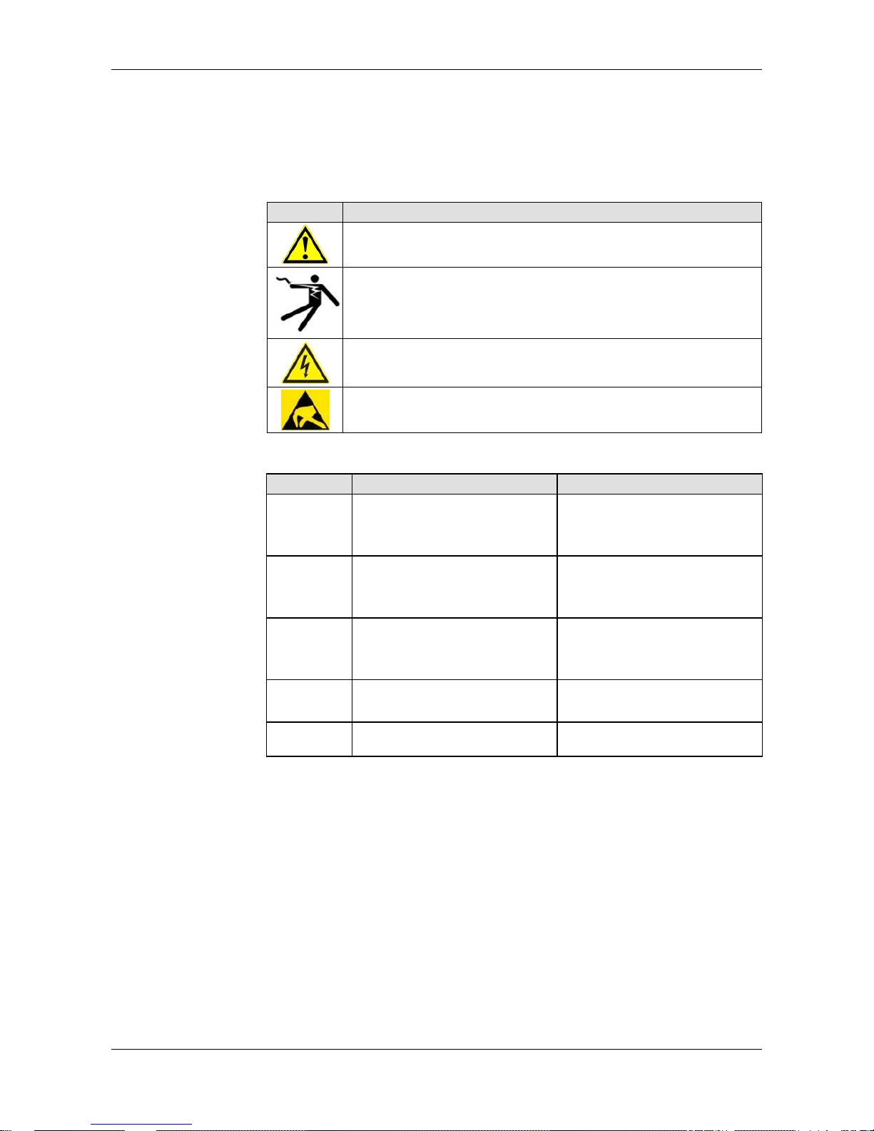
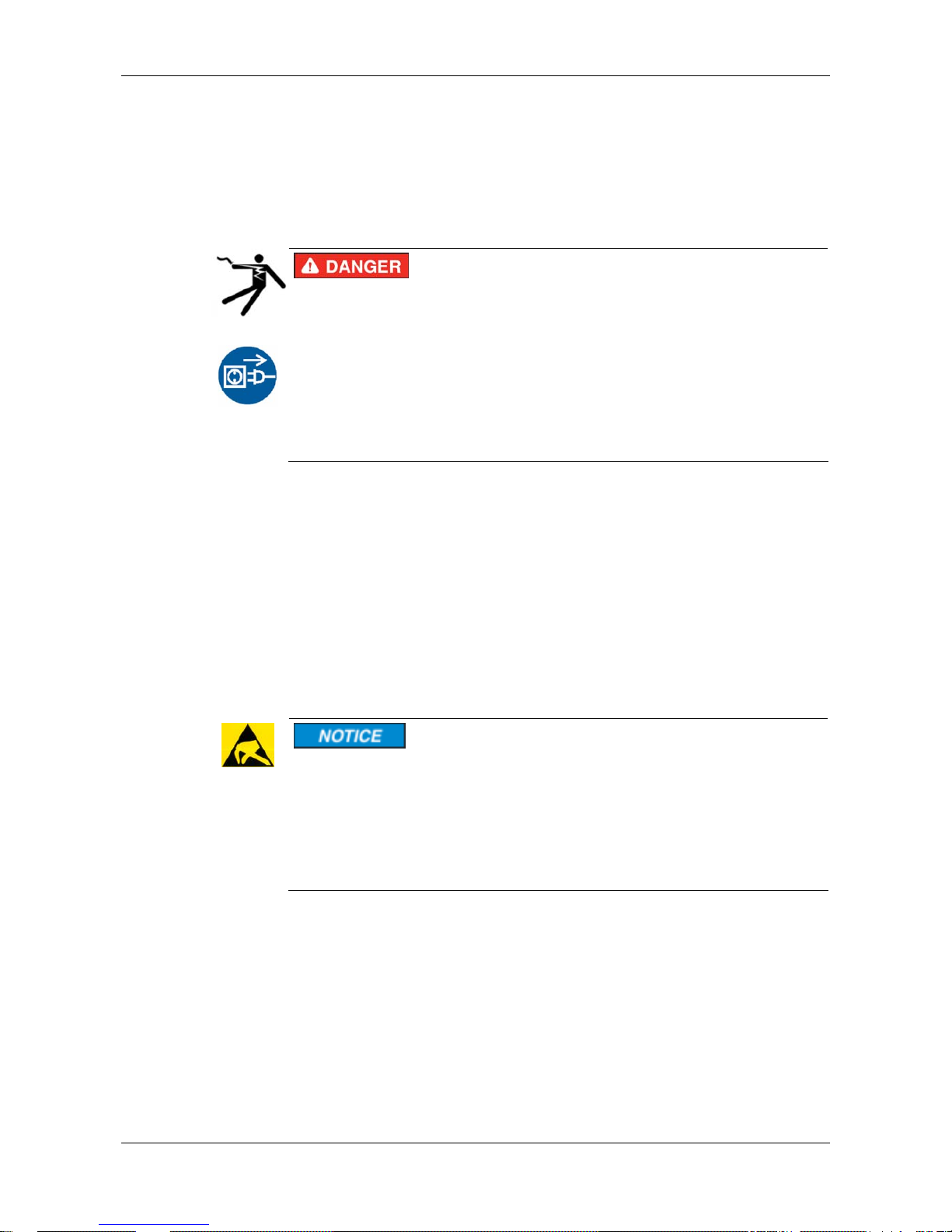
2.5 Labeling of Safety Instructions
The safety instructions are pinpointed particularly. The instructions are
highlighted with a specific safety symbol, a warning triangle and a signal
word according to the degree of endangerment. Inside the note the danger
is exactly named. Instructions to a property damage message do not
contain a warning triangle.
Symbol Sort of Warning or Principle
Safety symbol for the warning to personal injury
Warning for Electrical Shock Hazard
Warning of danger by electrical current
Warning of damages by electrostatic discharge
Table 10: Safety Symbols and Sort of Warning or Principle
Signal Word Meaning Meaning (ANSI)
DANGER
Indicates a direct hazard with high
risk, which will have as
consequence death or grievous
bodily harm if it isn't avoided.
Indicates a Hazardous Situation
Which, if not Avoided, will Result in
Death or Serious Injury.
WARNING
Indicates a possible hazard with
medium risk, which will have as
consequence death or (grievous)
bodily harm if it isn't avoided.
Indicates a Hazardous Situation
Which, if not Avoided, could Result
in Death or Serious Injury.
CAUTION
Indicates a minor hazard with
medium risk, which could have as
consequence simple battery if it isn't
avoided.
Indicates a Hazardous Situation
Which, if not Avoided, may Result in
Minor or Moderate Injury.
NOTICE
Indicates a Property Damage
Message.
Indicates a Property Damage
Message.
Note
Indicates an important note in the
manual.
Indicates an Important Note in the
Manual.
Table 11: Signal Words
Page 16
Safety 16/142
netPLC C100 | Startup Guide
DOC090701UM02EN | Revision 2 | English | 2009-10 | Released | Public © Hilscher, 2009
2.6 Safety Instructions
This manual contains instructions which must be observed to ensure your
own personal safety and to avoid damage to devices.
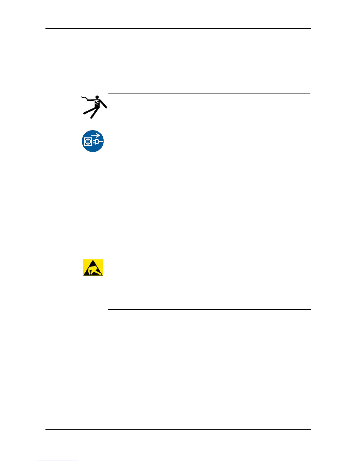
2.6.1 Electrical Shock Hazard
Electrical Shock Hazard
HAZARDOUS VOLT AGE inside of the PC or of the connecting device.
Therefore f irst disconnect the power plug of the PC or of the connecting
device.
Make sure, that the power supply is off at the PC or at the connecting
device.
Open the PC cabinet and install or remove the slot PLC only after
disconnecting power.
2.7 Property Damage Messages
This manual contains instructions which must must be red, understod and
observed to avoid damage to devices.
2.7.1 Electrostatically sensitive Devices
Adhere to the necessary safety precautions for components that are
vulnerable with electrostatic discharge (EN 61340-5-1 and EN 61340-5-2
as well as IEC 61340-5-1 and IEC 61340-5-2).
CAUTION!
Electrostatically sensitive Devices
This equipment is sensitive to electrostatic discharge, which cause
internal damage and affect normal operation. Follow guidelines when you
handle this equipment.
Observe the necessary safety precautions when handling components
that are vulnerable to electrostatic discharge.
Page 17
Safety 17/142
netPLC C100 | Startup Guide
DOC090701UM02EN | Revision 2 | English | 2009-10 | Released | Public © Hilscher, 2009
2.8 Safety Instructi ons USA
This manual contains instructions which must be observed to ensure your
own personal safety and to avoid damage to devices.
2.8.1 Electrical Shock Hazard
Electrical Shock Hazard
HAZARDOUS VOLT AGE inside of the PC or of the connecting device.
Therefore f irst disconnect the power plug of the PC or of the connecting
device.
Make sure, that the power supply is off at the PC or at the connecting
device.
Open the PC cabinet and install or remove the XXX card only after
disconnecting power.
2.9 Property Damage Messages USA
This manual contains instructions which must must be red, understod and
observed to avoid damage to devices.
2.9.1 Electrostatically sensitive Devices
Adhere to the necessary safety precautions for components that are
vulnerable with electrostatic discharge (EN 61340-5-1 and EN 61340-5-2
as well as IEC 61340-5-1 and IEC 61340-5-2).
Electrostatic Discharge
This equipment is sensitive to electrostatic discharge, which cause
internal damage and affect normal operation. Follow guidelines when you
handle this equipment.
Observe the necessary safety precautions when handling components
that are vulnerable to electrostatic discharge.
Page 18

Description and Requirements 18/142
netPLC C100 | Startup Guide
DOC090701UM02EN | Revision 2 | English | 2009-10 | Released | Public © Hilscher, 2009
3 Description and Requirements
3.1 Description
The slot PLC described in this user manual is a PC card with PLC
functionality and fieldbus communication. Depending from the loaded
firmware, the fieldbus systems listed in the following table can be r ealized
using the respective slot PLC.
Slot PLC Fieldbus System
NPLC-C100-DP/CDS-OPC PROFIBUS-DP Master
Table 12: Slot PLC
These slot PLC device is a PC card for fieldbus communication and
handles the complete data exchange between the connected fieldbus
devices and CoDeSys.
In one PC a maximum of two slot PLC can be used.
Page 19

Description and Requirements 19/142
netPLC C100 | Startup Guide
DOC090701UM02EN | Revision 2 | English | 2009-10 | Released | Public © Hilscher, 2009
3.2 System Requirements
3.2.1 System Requirements PC
• Windows® XP
• PC with PCI connector with 5 V for hardware revision 3 of “NPLC C100-
DP“
• PC with PCI connector with 3,3 V respectively 5 V for hardware revision
4 of “NPLC C100-DP“
• DVD ROM drive
• Graphic resolution: min. 1024 x 768 pixel or higher
• Keyboard and Mouse
3.2.2 System Requirements CoDeSys
System requirements for the programming system CoDeSys with
configuration software SYCON.net. The configuration software SYCON. net
is contained in CoDeSys as Plug In.
• Windows
®
XP
• Internet Explorer 5.5 or higher
• Free disk space: min. 400 MByte, recommended 1 GByte
• RAM: min. 512 MByte, recommended 1024 MByte
• Graphic resolution: min. 1024 x 768 pixel
• Keyboard and Mouse
Note: If the project file is saved and opened again or it is used on another
PC, the system requirements need to match. Particularly the DT Ms need
to be installed on the used PC.
Page 20
Description and Requirements 20/142
netPLC C100 | Startup Guide
DOC090701UM02EN | Revision 2 | English | 2009-10 | Released | Public © Hilscher, 2009
3.3 Requirements for Operation
Note: Upgrade older versions of the cifX Device Driver necessarily on
the version V0.945.
3.3.1 Slot PLC
For the slot PLC operation as a master the following requirements must be
fulfilled:
Protocol
PROFIBUS-DP Master
The device driver cifX Device Driver has to be installed (from
V0.945).
Software
Installation
The netPLC CoDeSys Server has to be installed and must run, if
communicating via PCI with the slot PLC.
Firmware
The firmware NPC1CDPM.NXF has to be loaded into the slot PLC.
License
Licenses are required for the operation of the slot PLC NPLC C100DP/CDS-OPC as a PROFIBUS-DP Master as well as for CoDeSys
SP. These licenses are included in the scope of delivery.
Configuration
Die slot PLC must be configured using the configuration software.
Programming
The PLC program must be created with CoDeSys and loaded into
the slot PLC.
Communication
For communication slave devices for the communication system
PROFIBUS-DP are required.
Table 13: Requirements for operation of the Slot PLC
Page 21

Device Drawings 21/142
netPLC C100 | Startup Guide
DOC090701UM02EN | Revision 2 | English | 2009-10 | Released | Public © Hilscher, 2009
4 Device Drawings
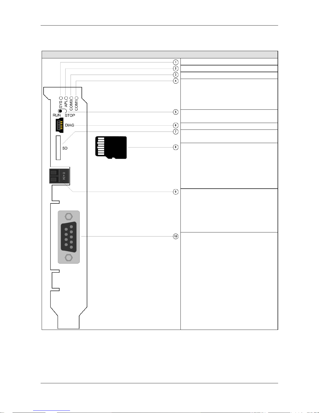
4.1 Device Drawing NPLC-C100-DP
Figure 1: Device Drawing NPLC-C100-DP
Number Designation
1 LED SYS
2 LED APL
3 LED COM0
4 LED COM1
5 RUN/STOP Switch
6 DIAG – USB Diagnostic Interface
7 Slot for Memory Card
8 MicroSD Memory Card
9 External Power Supply
10 PROFIBUS Interface
11 Battery holder
12 Battery
Table 14: Designation in the Device Drawing NPLC-C100-DP
Page 22
Device Drawings 22/142
netPLC C100 | Startup Guide
DOC090701UM02EN | Revision 2 | English | 2009-10 | Released | Public © Hilscher, 2009
4.1.1 Cover NPLC-C100-DP
Designation
LED SYS
LED APL
LED COM0
LED COM1
RUN/STOP Switch
DIAG – USB Diagnostic Interface
Slot for Memory Card
MicroSD Memory Card
External Power Supply
PROFIBUS Interface
Table 15: Designation in the cover of NPLC-C100-DP
Page 23

System Overview 23/142
netPLC C100 | Startup Guide
DOC090701UM02EN | Revision 2 | English | 2009-10 | Released | Public © Hilscher, 2009
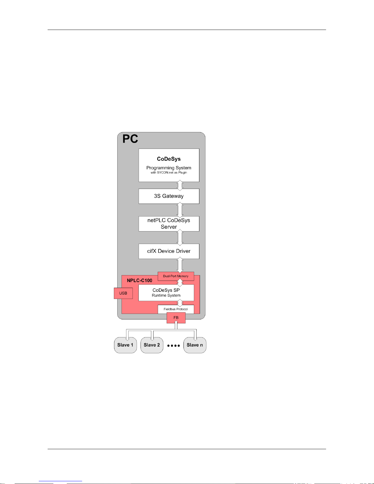
5 System Overview
The CoDeSys programming system and the slot PLC may be installed on
the same PC or on two separate PCs.
The following system overview shows beside the CoDeSys programming
system and the slot PLC additional components, how these communicate
together and which component needs to be installed on which PC.
The following components are important:
• CoDeSys programming system inclusive bus configuration software
• 3S Gateway
• netPLC CoDeSys Server and the
• Card’s Device Driver (cifX Device Driver).
Page 24
System Overview 24/142
netPLC C100 | Startup Guide
DOC090701UM02EN | Revision 2 | English | 2009-10 | Released | Public © Hilscher, 2009
Use Case 1:
The CoDeSys programming system and the slot PLC are installed on the
same PC as use case 1. The following software components are necessary
on this PC:
• CoDeSys programming system inclusive bus configuration software
• 3S Gateway
• netPLC CoDeSys Server and the
• Device Driver (cifX Device Driver) .
Figure 2: System Overview – Use Case 1 (One PC)
Page 25
System Overview 25/142
netPLC C100 | Startup Guide
DOC090701UM02EN | Revision 2 | English | 2009-10 | Released | Public © Hilscher, 2009
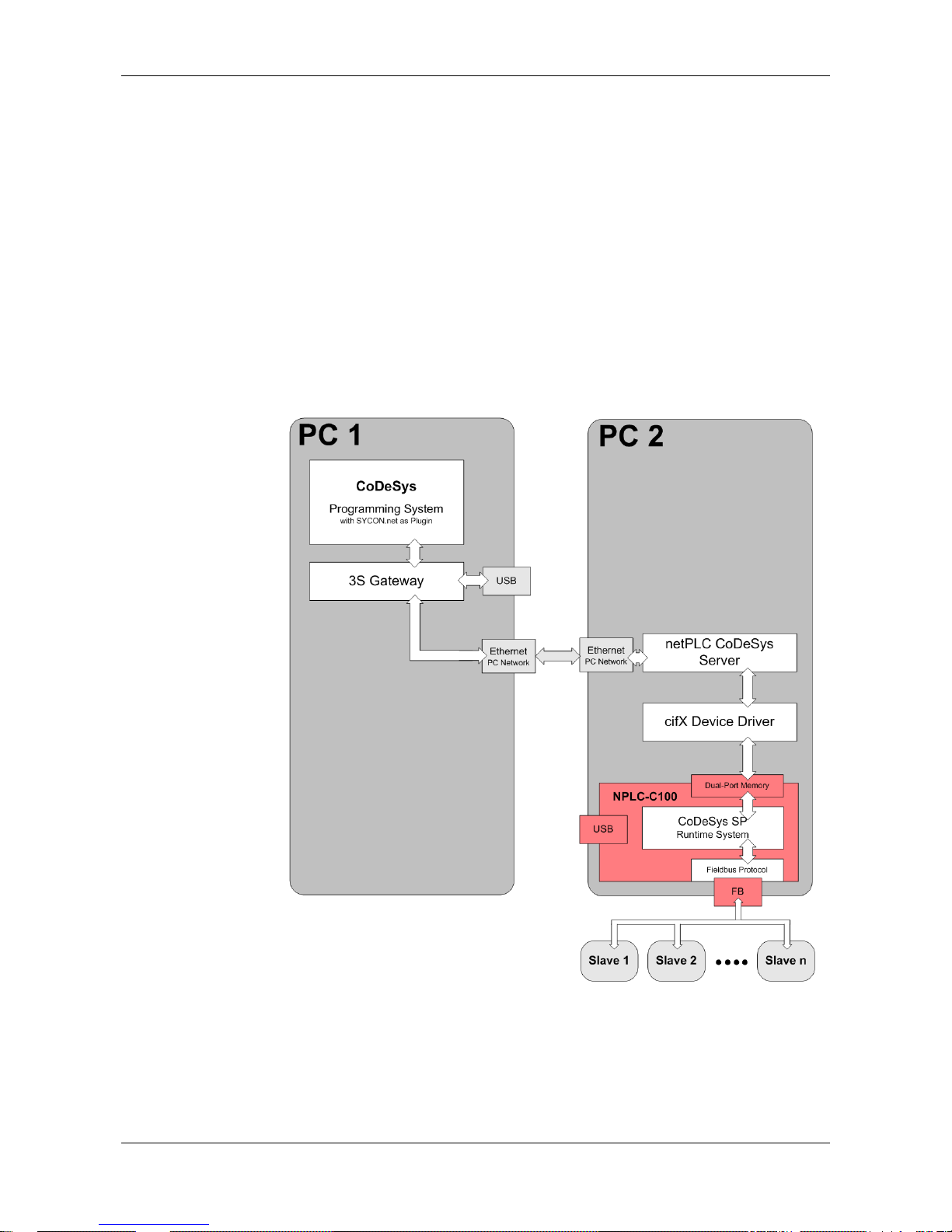
Use Case 2:
The CoDeSys programming system is installed on PC1 and the slot PLC is
installed in PC2 as use case 2. Both PC are connected via Ethernet (local
network).
The following software components are necessary for PC1:
• CoDeSys programming system inclusive bus configuration software
• 3S Gateway
The following software components are necessary for PC2:
• netPLC CoDeSys Server and the
• Device Driver (cifX Device Driver) .
Figure 3: System Overview – Use Case 2 (Two PCs with Ethernet Connection)
Page 26
System Overview 26/142
netPLC C100 | Startup Guide
DOC090701UM02EN | Revision 2 | English | 2009-10 | Released | Public © Hilscher, 2009
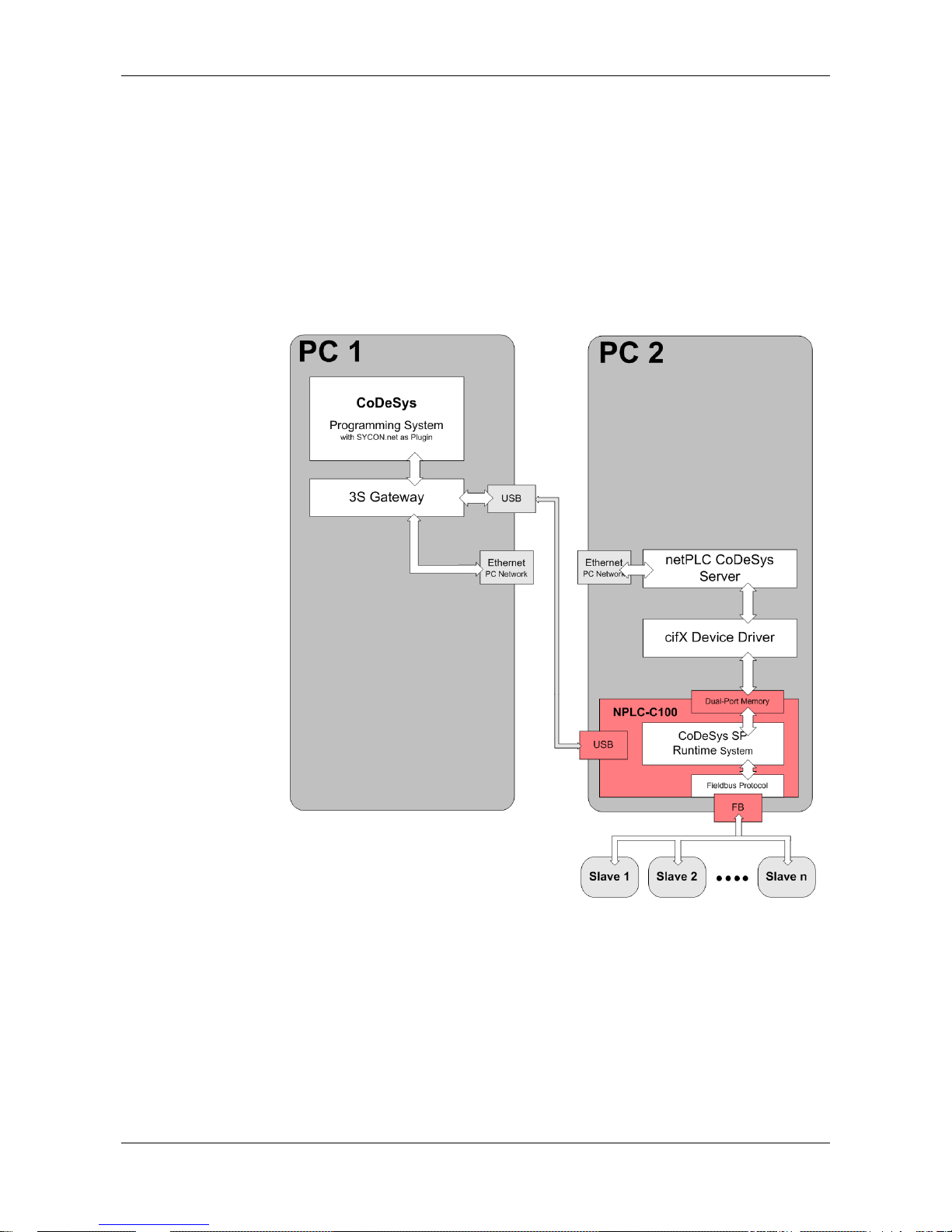
Use Case 3:
The CoDeSys programming system is installed on PC1 and the slot PLC is
installed in PC2 as use case 3. The USB port of PC1 is connected via an
USB cable to the USB port of the Slot PLC.
The following software components are necessary for PC1:
• CoDeSys programming system inclusive bus configuration software
• 3S Gateway
Figure 4: System Overview – Use Case 2 (Two PCs with USB Connection)
The following software components are necessary for PC2 to connect to a
visualization software:
• netPLC CoDeSys Server and the
• Device Driver (cifX Device Driver) .
Page 27
Installing Software 27/142
netPLC C100 | Startup Guide
DOC090701UM02EN | Revision 2 | English | 2009-10 | Released | Public © Hilscher, 2009
6 Installing Software
The software installation installs the following components:
• CoDeSys programming system (with 3S Gateway and bus configuration
software)
• Device Driver (cifX Device Driver) and the
• netPLC CoDeSys Server.
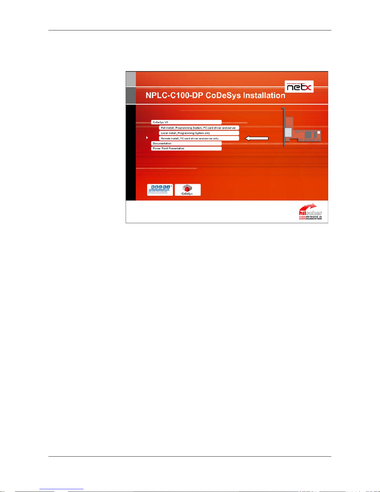
1. Insert the netPLC DVD into your local DVD ROM drive.
2.
Select CoDeSys V3 of the auto start menu.
Note: Administrator privileges are required on Windows
®
XP systems for
installation!
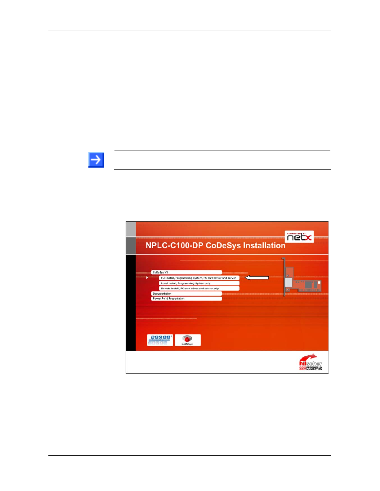
3. Select installation amount
Three selection are available:
¾
Select Full Install, Programming System, PC card driver and server,
when you want to install the programming system and the slot PLC in
the same PC.
Figure 5: netPLC auto start – Full Installation
°
The following setups are started one after the other:
bus configuration software
CoDeSys programming system
device driver (cifX Device Driver)
netPLC CoDeSys Server
Page 28
Installing Software 28/142
netPLC C100 | Startup Guide
DOC090701UM02EN | Revision 2 | English | 2009-10 | Released | Public © Hilscher, 2009
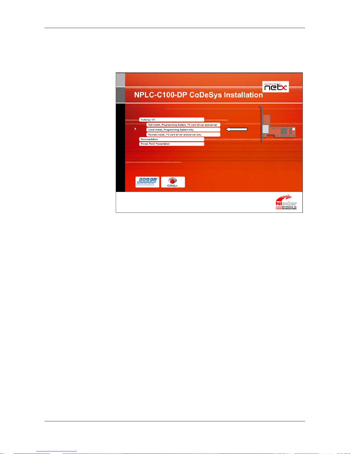
¾
Select Local Install, Programming System only, when you want to
install the programming system on one PC and the slot PLC in an othe
r
PC. The programming system can communicate via Ethernet with t he
PC with the slot PLC or via USB with the slot PLC.
Figure 6: netPLC auto start – Local Installation
°
The following setups are started one after the other:
bus configuration software
CoDeSys programming system
Page 29
Installing Software 29/142
netPLC C100 | Startup Guide
DOC090701UM02EN | Revision 2 | English | 2009-10 | Released | Public © Hilscher, 2009
¾
Select Remote Install, PC card driver and server only, when you
want to install the slot PLC device driver and server. This is the PC with
the slot PLC.
Figure 7: netPLC auto start – Remote Installation
°
The following setups are started one after the other:
device driver (cifX Device Driver)
netPLC CoDeSys Server
Page 30
Installing Software 30/142
netPLC C100 | Startup Guide
DOC090701UM02EN | Revision 2 | English | 2009-10 | Released | Public © Hilscher, 2009
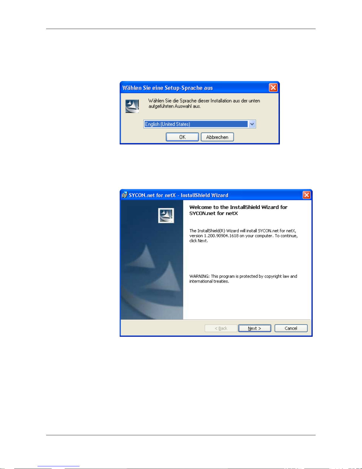
6.1 Plug In SYCON.net Setup
1. Language for the setup
¾
Select the language for the setup
¾
Click on OK.
2. Continue installation
¾
Click on Next > to continue the installation.
Page 31

Installing Software 31/142
netPLC C100 | Startup Guide
DOC090701UM02EN | Revision 2 | English | 2009-10 | Released | Public © Hilscher, 2009
3. Accept license agreement
¾
Select I accept the terms in the license agreement, when you agree
to it.
¾
Click on Next > to continue the installation.
Page 32

Installing Software 32/142
netPLC C100 | Startup Guide
DOC090701UM02EN | Revision 2 | English | 2009-10 | Released | Public © Hilscher, 2009
4. Enter user information
¾
Enter the user name
¾
Enter the name of the organization
¾
Click on Next > to continue the installation.
Page 33

Installing Software 33/142
netPLC C100 | Startup Guide
DOC090701UM02EN | Revision 2 | English | 2009-10 | Released | Public © Hilscher, 2009
5. Select setup type
¾
Select Complete when you want to install the complete software.
¾
Click on Next > to continue the installation.
6. Installation
¾
Click on Install to do the installation now.
°
The components are installed. This will take several minutes.
Page 34

Installing Software 34/142
netPLC C100 | Startup Guide
DOC090701UM02EN | Revision 2 | English | 2009-10 | Released | Public © Hilscher, 2009
7. Finish installation
¾
Click on Finish
°
The software is installed.
Page 35

Installing Software 35/142
netPLC C100 | Startup Guide
DOC090701UM02EN | Revision 2 | English | 2009-10 | Released | Public © Hilscher, 2009
6.2 CoDeSys Progr amming System Setup
1. Accept installation
¾
Click on Next to start the installation.
2. License agreement
¾
Click on Yes when you accept the license agreement.
¾
When you want to print the license agreement then select Print.
Page 36

Installing Software 36/142
netPLC C100 | Startup Guide
DOC090701UM02EN | Revision 2 | English | 2009-10 | Released | Public © Hilscher, 2009
3. Define destination folder
¾
Select Browse when you want to change the default destination folde
r
and enter the new destination folder then.
¾
Click on Next.
Page 37

Installing Software 37/142
netPLC C100 | Startup Guide
DOC090701UM02EN | Revision 2 | English | 2009-10 | Released | Public © Hilscher, 2009
4. Define installation amount
¾
Select as minimum
CoDeSys V3
CoDeSys Gateway
CoDeSys OPC Server 3
CoDeSys Gateway V2.3
°
¾
Click on Next.
Page 38

Installing Software 38/142
netPLC C100 | Startup Guide
DOC090701UM02EN | Revision 2 | English | 2009-10 | Released | Public © Hilscher, 2009
5. Define Program Folder
¾
The default program folder is 3S CoDeSys. If you want to use an othe
r
program folder then enter it now.
¾
Click on Next.
Page 39

Installing Software 39/142
netPLC C100 | Startup Guide
DOC090701UM02EN | Revision 2 | English | 2009-10 | Released | Public © Hilscher, 2009
6. Summary
°
¾
Click on Next.
7. Installation is processed
°
The components are installed. This will take several minutes.
°
Manufacturer specific components (Vendor AddOn) are installed.
Page 40

Installing Software 40/142
netPLC C100 | Startup Guide
DOC090701UM02EN | Revision 2 | English | 2009-10 | Released | Public © Hilscher, 2009
8. Important information
°
¾
Read the information
¾
Select I read the information, when you have read the information.
¾
Click on Next.
Page 41

Installing Software 41/142
netPLC C100 | Startup Guide
DOC090701UM02EN | Revision 2 | English | 2009-10 | Released | Public © Hilscher, 2009
9. Finish installation
¾
Click on Finish.
Page 42

Installing Software 42/142
netPLC C100 | Startup Guide
DOC090701UM02EN | Revision 2 | English | 2009-10 | Released | Public © Hilscher, 2009
6.3 Device Driver Setup
1. Language for the setup
¾
Select the language for the setup
¾
Click on OK.
2. Continue installation
¾
Click on Next > to continue.
Page 43

Installing Software 43/142
netPLC C100 | Startup Guide
DOC090701UM02EN | Revision 2 | English | 2009-10 | Released | Public © Hilscher, 2009
3. Installation
¾
Click on Install to start the installation now.
°
The device driver is (pre)installed.
4. Message: Device Driver is prepared
¾
Click on OK to confirm
Page 44

Installing Software 44/142
netPLC C100 | Startup Guide
DOC090701UM02EN | Revision 2 | English | 2009-10 | Released | Public © Hilscher, 2009
5. Finish installation
¾
Click on Finish.
°
The installation is completed.
Page 45

Installing Software 45/142
netPLC C100 | Startup Guide
DOC090701UM02EN | Revision 2 | English | 2009-10 | Released | Public © Hilscher, 2009
6.4 netPLC CoDeSys Server Setup
1. Continue installation
¾
Click on Next > (Weiter >) to continue
2. Installation
¾
Click on Install (Installieren) to start the installation now
°
The software is installed.
Page 46

Installing Software 46/142
netPLC C100 | Startup Guide
DOC090701UM02EN | Revision 2 | English | 2009-10 | Released | Public © Hilscher, 2009
3. Finish installation
¾
Click on Finish (Fertigstellen) to finish
°
The software is installed.
Note: The netPLC CoDeSys Server starts automatically, when the PC is
started.
Page 47

Installing Software 47/142
netPLC C100 | Startup Guide
DOC090701UM02EN | Revision 2 | English | 2009-10 | Released | Public © Hilscher, 2009
6.5 Installing the Device Driver
Note: In case the Slot SPS was installed as described in section Installing
Slot PLC NPLC C100-DP on page 56 then the Windows
®
Hardware
Detection asks for a driver with the next start of the PC.
1. Switch on the PC
¾
After installing the slot PLC switch on your PC.
°
Windows
®
XP detects the slot PLC automatically.
°
The message Found New Hardware is displayed and the Found new
Hardware Wizard is started.
2. Windows Update
¾
Select No, not this time
¾
Click on Next > to continue
Page 48

Installing Software 48/142
netPLC C100 | Startup Guide
DOC090701UM02EN | Revision 2 | English | 2009-10 | Released | Public © Hilscher, 2009
3. Install software automatically
¾
Select Install software automatically
¾
Click on Next > to continue.
°
The preinstalled device driver is found and installed then.
Page 49

Installing Software 49/142
netPLC C100 | Startup Guide
DOC090701UM02EN | Revision 2 | English | 2009-10 | Released | Public © Hilscher, 2009
4. Finish installation
¾
Click on Finish
°
The installation is completed.
5.
Check in the Device Manager if t he driver for the slot PLC is installed
properly.
¾
Open the Device Manager: Desktop symbol My Computer > right
mouse button Properties > Tab Hardware > button Device Manager.
¾
Check, if the display in the Device Manager shows
netPLC C100 PCI/PCIe Device
Page 50

Installing Software 50/142
netPLC C100 | Startup Guide
DOC090701UM02EN | Revision 2 | English | 2009-10 | Released | Public © Hilscher, 2009
6.6 Installing USB Driver
Note: If the slot PLC is connected via USB to your PC, then the Windows
®
Hardware detection asks for a driver.
1. Connect a USB cable
¾
Connect a USB cable your PC with the USB port of the slot PLC.
°
Windows
®
XP detects the slot PLC automatically.
°
The message Found New Hardware is displayed and the Found new
Hardware Wizard is started.
2. Windows update
¾
Select No, not this time
¾
Click on Next > to continue.
Page 51

Installing Software 51/142
netPLC C100 | Startup Guide
DOC090701UM02EN | Revision 2 | English | 2009-10 | Released | Public © Hilscher, 2009
3. Install software automatically
¾
Select Install from a list or specific location
¾
Click on Next > to continue.
Page 52

Installing Software 52/142
netPLC C100 | Startup Guide
DOC090701UM02EN | Revision 2 | English | 2009-10 | Released | Public © Hilscher, 2009
4. Insert the netPLC-C100 DVD into your local DVD ROM drive
¾
Insert the netPLC-C100 DVD into your local DVD ROM drive
¾
Select Search for the best driver in these locations
¾
Select Include this location in the search
¾
Click on Browse
¾
Select the folder Drivers\USB\Windows .INF from the DVD
¾
Click on Next > to continue.
°
The USB driver is installed
Page 53

Installing Software 53/142
netPLC C100 | Startup Guide
DOC090701UM02EN | Revision 2 | English | 2009-10 | Released | Public © Hilscher, 2009
5. Finish installation
¾
Click on Finish
°
The Installation is completed.
6.
Check in the Device Manager if t he driver for the slot PLC is installed
properly.
¾
Open the Device Manager: Desktop symbol My Computer > right
mouse button Properties > Tab Hardware > button Device Manager.
¾
Check, if the display in the Device Manager shows
netPLC (COMx)
Page 54

Installing Hardware (Slot PLC) 54/142
netPLC C100 | Startup Guide
DOC090701UM02EN | Revision 2 | English | 2009-10 | Released | Public © Hilscher, 2009
7 Installing Hardware (Slot PLC)
7.1 Safety Advices
Obey to the following safety advices, when installing the slot PLC.
Electrical Shock Hazard
HAZARDOUS VOLT AGE inside of the PC or of the connecting device.
Therefore f irst disconnect the power plug of the PC or of the connecting
device.
Make sure, that the power supply is off at the PC or at the connecting
device.
Open the PC cabinet and install or r emove the slot PLC car d only after
disconnecting power.
CAUTION!
Electrostatically sensitive Devices
To prevent damage to the PC and the slot PLC, make sure, that the slot
PLC is grounded via the endplate and the PC and make sure, that you
are discharged when you mount/demount the slot PLC.
7.1.1 Safety Advices USA
Obey to the following safety advices, when installing the slot PLC.
Electrical Shock Hazard
HAZARDOUS VOLT AGE inside of the PC or of the connecting device.
Therefore f irst disconnect the power plug of the PC or of the connecting
device.
Make sure, that the power supply is off at the PC or at the connecting
device.
Open the PC cabinet and install or r emove the slot PLC card only after
disconnecting power.
Electrostatically sensitive Devices
To prevent damage to the PC and the slot PLC, make sure, that the slot
PLC is grounded via the endplate and the PC and make sure, that you
are discharged when you mount/demount the slot PLC.
Page 55

Installing Hardware (Slot PLC) 55/142
netPLC C100 | Startup Guide
DOC090701UM02EN | Revision 2 | English | 2009-10 | Released | Public © Hilscher, 2009
7.2 Installing Battery
With delivery a protection foil protects the battery against discharge.
Remove protection foil
¾
Remove the protection foil to activate the battery buffering.
°
Æ
Page 56

Installing Hardware (Slot PLC) 56/142
netPLC C100 | Startup Guide
DOC090701UM02EN | Revision 2 | English | 2009-10 | Released | Public © Hilscher, 2009
7.3 Installing Slot PLC NPLC C100-DP
For installation of the slot PLC handle as follows:
1. Disconnect the power plug of the PC.
2. Open the cabinet of the PC.
3. Plug in the slot PLC on a free PCI slot
4. Fix the slot PLC using the hole intended.
5. Close the PC casing.
6. Connect the external 24 V power supply.
7. Connect the PC to the power supply and switch on the PC.
Page 57

First Project 57/142
netPLC C100 | Startup Guide
DOC090701UM02EN | Revision 2 | English | 2009-10 | Released | Public © Hilscher, 2009
8 First Project
8.1 Overview
This section describes how a project is created for the slot PLC. It is
assumed that the hardware (slot PLC) and software already is installed.
Additionally a PROFIBUS-DP slave device and a PROFIBUS cable are
needed.
If the project is loaded via USB into the slot PLC, then a USB cable with
type A to type mini B is needed.
An important note in advance:
Important: The name of the application has to be reduced. The name of
the application can have 7 characters as maximum. The target device
supports the MS-DOS file format 8.3 and no long file names. Application
names with more than 7 characters can not
be started in the target device.
The eights character is used internally and therefore is reserved.
Page 58

First Project 58/142
netPLC C100 | Startup Guide
DOC090701UM02EN | Revision 2 | English | 2009-10 | Released | Public © Hilscher, 2009
8.2 Preparation
8.2.1 netPLC CoDeSys Server
The netPLC CoDeSys server program is started automatically with each
start of the PC after the installation from DVD.
Note: Make sure that the server runs, if no USB is used.
Note: The netPLC CoDeSys server program must always be started
before CoDeSys is started.
1. Check if netPLC CoDeSys server is running
¾
Check, that the netPLC CoDeSys server is running, the symbol
has
to be shown in the system tray
¾
If the netPLC CoDeSys server is not running, then start it now: Start >
All Programs > Hilscher GmbH > netPLC CoDeSys Server.
°
The system tray shows the symbol
.
Page 59

First Project 59/142
netPLC C100 | Startup Guide
DOC090701UM02EN | Revision 2 | English | 2009-10 | Released | Public © Hilscher, 2009
8.2.2 CoDeSys
Note: Start CoDeSys always with the profile “for netPLC“
1. Start CoDeSys
¾
Select Start > All Programs > 3S CoDeSys > CoDeS ys > CoDeSys
V3.3 SPx Patch x for netPLC or
¾
Start CoDeSys by a double click on the desktop icon
°
CoDeSys is started.
Page 60

First Project 60/142
netPLC C100 | Startup Guide
DOC090701UM02EN | Revision 2 | English | 2009-10 | Released | Public © Hilscher, 2009
°
The CoDeSys GUI appears.
Page 61

First Project 61/142
netPLC C100 | Startup Guide
DOC090701UM02EN | Revision 2 | English | 2009-10 | Released | Public © Hilscher, 2009
8.3 Create Control Program and Bus Configuration
8.3.1 Create Project
1. Create a new project
¾
Select File > New Project
°
The window New Project appears.
Page 62

First Project 62/142
netPLC C100 | Startup Guide
DOC090701UM02EN | Revision 2 | English | 2009-10 | Released | Public © Hilscher, 2009
2. Set up project-relevant information
¾
Select category (General) at Categories
¾
Select Standard project at Templates
¾
Fill in the project name FirstProject in the field Name
¾
Select a folder for storage of project data in t he field Location such as:
C:\Projekt
¾
Click at button OK with the left mouse button.
°
The window New Project is being closed and the selection window
Standard Project appears
3. Set up information regarding the standard project
¾
Select the device entry NPLC-C100-DP (Hilscher GmbH) at Device
¾
At PLC_PRG in select the programming mode Structured Text (ST)
¾
Click at button OK with the left mouse button.
Page 63

First Project 63/142
netPLC C100 | Startup Guide
DOC090701UM02EN | Revision 2 | English | 2009-10 | Released | Public © Hilscher, 2009
°
The window Standard Project is being closed and the project tree
appears:
4. Switch to the device view
¾
Check that the view is switched to
.
¾
If the view has been switched to POUs, then click onto the tab
using the left mouse button in order to switch to the device
view
°
Now the device view is activated.
5. Save project
¾
Save project using menu entry File > Save Project
°
The project is saved.
Page 64

First Project 64/142
netPLC C100 | Startup Guide
DOC090701UM02EN | Revision 2 | English | 2009-10 | Released | Public © Hilscher, 2009
Important: The name of the application has to be reduced. The name of
the application can have 7 characters as maximum. The target device
supports the MS-DOS file format 8.3 and no long file names. Application
names with more than 7 characters can not be executed in the target
device. The eights character is used internally and therefore is reserved.
6. Set name of application
¾
Single-click with the left mouse button at the name Application:
and change the name to App ( a nam e with less than 7 characters).
°
A security request appears
Page 65

First Project 65/142
netPLC C100 | Startup Guide
DOC090701UM02EN | Revision 2 | English | 2009-10 | Released | Public © Hilscher, 2009
7. Rename the application
¾
Answer with Yes to the security request
°
The name of the application is changed to App.
Page 66

First Project 66/142
netPLC C100 | Startup Guide
DOC090701UM02EN | Revision 2 | English | 2009-10 | Released | Public © Hilscher, 2009
8.3.2 Add PROFIBUS-DP Slave Device by use of a GSD File
1. Add PROFIBUS-DP slave device by use of a GSD file
¾
If you want to add PROFIBUS-DP slave devices to your device catalog ,
then copy the GSD file(s) of your slave device(s) into this folder:
E:\Documents and Settings\All Users\Application Data\
SYCONnet\PROFIBUS\GSD
2. Open window SYCON.net options
¾
Select menu Tools > Options
¾
Select option Sycon.net
°
3. Reload catalog
¾
Click on Reload Catalog to update the device catalog
°
The device catalog is reloaded
4. Close options window
¾
Click on OK to close the window.
Page 67

First Project 67/142
netPLC C100 | Startup Guide
DOC090701UM02EN | Revision 2 | English | 2009-10 | Released | Public © Hilscher, 2009
8.3.3 Bus Configuration
1. Opening the configuration window
¾
Open the configuration window with a double click a
t
NPLC_PROFIBUS (NPLC_PROFIBUS).
°
The configuration window NPLC_PROFIBUS with the tab Configurato
r
appears.
Page 68

First Project 68/142
netPLC C100 | Startup Guide
DOC090701UM02EN | Revision 2 | English | 2009-10 | Released | Public © Hilscher, 2009
2. Insert PROFIBUS-DP Slave Device
¾
Select from the Device Catalog a PROFIBUS-DP Slave Device such as
the CB_AB32-DPS for instance and drag and drop the device icon to
the bus line.
°
The slave device appears at the PROFIBUS bus line.
Page 69

First Project 69/142
netPLC C100 | Startup Guide
DOC090701UM02EN | Revision 2 | English | 2009-10 | Released | Public © Hilscher, 2009
3. Open the slave configuration window
¾
Open the configuration window of the slaves with a double click t he icon
of the slave device.
¾
Select the entry Module in the navigation area.
¾
The slave device used in this example already has selected modules at
Configured Modules. If you use an other slave then insert modules
from Available Modules to Configured Modules by using the insert
button.
°
In Configured Modules the information is displayed that the slave
device occupies 2 byte of input data and 2 byte of output data.
4. Close the configuration window
¾
Click on OK to close the windows and to apply the settings.
°
The window closes and the settings are applied.
Page 70

First Project 70/142
netPLC C100 | Startup Guide
DOC090701UM02EN | Revision 2 | English | 2009-10 | Released | Public © Hilscher, 2009
5. Open the window for Master configuration
¾
Open by a double click on the icon for the Master the configuration
window for the master.
¾
Select in the navigation area Bus Parameters.
°
6. Set Baud Rate
¾
Set at Baud Rate the Baud Rate, e. g. 1500 for 1, 5 MBit/s
Page 71

First Project 71/142
netPLC C100 | Startup Guide
DOC090701UM02EN | Revision 2 | English | 2009-10 | Released | Public © Hilscher, 2009
7. Set stations address of the PROFIBUS-DP slave(s)
¾
Select in the navigation area Station Table.
¾
Set in the column Station Address the address of the PROFIBUS-DP
slave device. The Master uses this address as slave identification to
communicate with the slave device.
°
8. Close the configuration window
¾
Click on OK to close the windows and to apply the settings.
°
The window closes and the settings are applied.
Page 72

First Project 72/142
netPLC C100 | Startup Guide
DOC090701UM02EN | Revision 2 | English | 2009-10 | Released | Public © Hilscher, 2009
9. Addressing of I/O data within the Fieldbus I/O image
¾
In the configuration window NPLC_PROFIBUS click at tab Fieldbus I/ O
Image in order to open the occupation of I/O data within the Fieldbus
I/O image.
¾
Open the variable tree.
°
The configuration window NPLC_PROFIBUS containing the tab
Fieldbus I/O Image appears.
The column Address shows the occupation of the I/O image. The input
addresses %IB0 und %IB1 and the output addresses %QB0 und %QB1
are occupied from the slave device CB_AB32-DPS. These addresses
are used in the PLC program.
10. Connect the PROFIBUS devices with a PROFIBUS cable
¾
Connect the Slot SPS with a PROFIBUS cable with the PROFIBUS-DP
slave device(s).
Page 73

First Project 73/142
netPLC C100 | Startup Guide
DOC090701UM02EN | Revision 2 | English | 2009-10 | Released | Public © Hilscher, 2009
8.3.4 Create PLC Program
1. Open Editor for function module PLC_PRG
¾
Open the Editor with a double click with the left mouse button a
t
PLC_PRG (PRG).
°
The editor window appears. The following picture shows the Edito
r
without any variables and PLC program.
Page 74

First Project 74/142
netPLC C100 | Startup Guide
DOC090701UM02EN | Revision 2 | English | 2009-10 | Released | Public © Hilscher, 2009
2. Create a variable
¾
Create variable following variables:
var1 : BYTE;
opc_ib0 : BYTE;
opc_ib1 : BYTE;
opc_qb0 : BYTE;
°
Page 75

First Project 75/142
netPLC C100 | Startup Guide
DOC090701UM02EN | Revision 2 | English | 2009-10 | Released | Public © Hilscher, 2009
3. Edit PLC Program
¾
Fill in the following PLC Program
var1 := var1 + 1;
%QB1 := var1;
opc_ib0 := %IB0;
opc_ib1 := %IB1;
%QB0 := opc_qb0;
°
A short explanation regarding the programming example
var1 := var1 + 1;
Variable var1 is incremented each PLC cycle.
%QB1 := var1;
The value of variable var1 is written to the output byte %QB1.
opc_ib0 := %IB0; und opc_ib1 := %IB1;
Input bytes %IB0 and %IB1 are copied to the variables opc_ib0 and
opc_ib1. This is the preparation, that the OPC server can access to the
input data.
%QB0 := opcqb0;
The value of variable opc_qb0 is copied to the output byte %QB0. This
is the preparation, that the OPC server can access to the output data.
Remark: Output byte %QB1 is used from the PLC program and
therefore can’t be accessed by the OPC server.
4. Save project
¾
Save project using menu entry File > Save Project
°
The project is saved.
Page 76

First Project 76/142
netPLC C100 | Startup Guide
DOC090701UM02EN | Revision 2 | English | 2009-10 | Released | Public © Hilscher, 2009
To create retain variables:
1. Create retain variables
¾
Create the section
VAR RETAIN
END_VAR
¾
Create a variable inside this section
VAR RETAIN
uiRemCount : UINT;
END_VAR
°
Page 77

First Project 77/142
netPLC C100 | Startup Guide
DOC090701UM02EN | Revision 2 | English | 2009-10 | Released | Public © Hilscher, 2009
8.3.5 Create Symbol Configuration
1. Add Object
¾
Select from the context menu on App t he entry Add Object.
°
The Object selection list appears.
Page 78

First Project 78/142
netPLC C100 | Startup Guide
DOC090701UM02EN | Revision 2 | English | 2009-10 | Released | Public © Hilscher, 2009
2. Add object symbol configuration
¾
Select from the window Add Object the entry Symbol Configuration.
¾
Click on Open
°
In the project tree the entry Symbol configuration appears.
°
In the editor window the tab Symbol configuration appears.
Page 79

First Project 79/142
netPLC C100 | Startup Guide
DOC090701UM02EN | Revision 2 | English | 2009-10 | Released | Public © Hilscher, 2009
3. Refresh available variables
¾
Click at Available Variables on Refresh.
°
The Available Variables are updated.
4. Show available variables
¾
Open below Available Items the tree Variables > PLC_PRG.
°
The variables opc_ib0, opc_ib1 and opc_qb0 appear.
Page 80

First Project 80/142
netPLC C100 | Startup Guide
DOC090701UM02EN | Revision 2 | English | 2009-10 | Released | Public © Hilscher, 2009
5. Add symbols to selected variables
¾
Mark in the tree below Available Variabl es the variable opc_ib0.
¾
Add this variable by a click on “>“ to the Selected Variables.
¾
Mark in the tree below Available Variabl es the variable opc_ib1.
¾
Add this variable by a click on “>“ to the Selected Variables.
¾
ark in the tree below Available Variables the variable opc_qb0.
¾
Add this variable by a click on “>“ to the Selected Variables.
°
The variables opc_ib0, opc_ib1 and opc_qb0 appear at Selected
Variables.
Page 81

First Project 81/142
netPLC C100 | Startup Guide
DOC090701UM02EN | Revision 2 | English | 2009-10 | Released | Public © Hilscher, 2009
8.3.6 Build Project
1. Build Project
¾
Select Build > Build App [Device: PLC Logic] F11 in order to build
the project
°
The project is being built.
2. Check the message window.
¾
Check that the message
Compile complete -- 0 errors, 0 warnings
appears in the message window:
°
The project has successfully been built.
3. Save project
¾
Save project using menu entry File > Save Project
°
The project is saved.
Page 82

First Project 82/142
netPLC C100 | Startup Guide
DOC090701UM02EN | Revision 2 | English | 2009-10 | Released | Public © Hilscher, 2009
8.4 Connect to the Slot PLC
8.4.1 Define Gateway
1.
Open the window Communication Settings.
¾
Open by double clicking with the left mouse butt on onto Device (NPLC-
C100-DP) the tab Communication Settings of the window Device.
°
The window Device with the tab Communication Set t ings appears.
Page 83

First Project 83/142
netPLC C100 | Startup Guide
DOC090701UM02EN | Revision 2 | English | 2009-10 | Released | Public © Hilscher, 2009
If no gateway appears, the do step 2 and 3. If a gateway already shows up,
then skip step 2 and 3.
2. Add Gateway
¾
Click at button Add Gateway.
°
The window Gateway appears
3. Accept Gateway
¾
Click at OK in order to accept setting Gateway-1.
°
The window Gateway is being closed.
Page 84

First Project 84/142
netPLC C100 | Startup Guide
DOC090701UM02EN | Revision 2 | English | 2009-10 | Released | Public © Hilscher, 2009
8.4.2 Scan Network and set Active Path
Note: Make sure that the server runs, if no USB is used.
Note: If you use a USB connection then check now that the USB cable is
connected.
1. Scan the network
¾
Click on Scan Network to search for NPLC-C100 devices
°
Devices are searched over the USB connection, via the parallel system
bus of the slot PLC via the netPLC CoDeSys server as well as via
Ethernet.
°
Found devices are displayed below Gateway-1.
Page 85

First Project 85/142
netPLC C100 | Startup Guide
DOC090701UM02EN | Revision 2 | English | 2009-10 | Released | Public © Hilscher, 2009
2 Set active path
¾
Click below Gateway-1 on the device NPLC-C100-DP to mark it.
¾
Click on Set active path to establish a connection to the device
°
Beside the device NPLC-C100-DP the text active appears.
Page 86

First Project 86/142
netPLC C100 | Startup Guide
DOC090701UM02EN | Revision 2 | English | 2009-10 | Released | Public © Hilscher, 2009
8.5 Download Control Program and Bus Configuration
8.5.1 Login and Download
1. Login to the slot PLC
¾
Select Online > Login to 'App [Device: PLC-Logic]'
°
The software verifies if the project in the slot PLC is the same as the
project on the PC. If no PLC program is in the slot PLC, then the
message “Application App does not exist on device. Do you want to
create it and proceed with download?“. If the projects are different then
the message “Unknown version of application App on taget. Do you
want to perform a download and replace the application?”.
Important: A download of the PLC program with login only stores the PLC
program not
zero voltage secure in the slot PLC. If the slot PLC is
disconnected from power supply then the downloaded PLC program and
bus configuration is deleted.
It is mandatory to create a boot application to store the PLC pr ogram and
the bus configuration permanently (zero voltage secure) in t he slot PLC.
This is described in section Create Boot Application on page 88.
Page 87

First Project 87/142
netPLC C100 | Startup Guide
DOC090701UM02EN | Revision 2 | English | 2009-10 | Released | Public © Hilscher, 2009
2. Start Download
¾
Answer the question “Application App does not exist on device. Do you
want to create it and proceed with download?“ with Yes.
°
The application is downloaded into the slot PLC.
°
With the start of the download the slot PLC goes into the stop mode.
°
The footer shows the progress of the download procedure: Sending
download info: Downloading … and shows the size of the alread
y
downloaded program and the complete size of the program.
Page 88

First Project 88/142
netPLC C100 | Startup Guide
DOC090701UM02EN | Revision 2 | English | 2009-10 | Released | Public © Hilscher, 2009
8.5.2 Create Boot Application
Important: It is mandatory to create a boot application t o store the PLC
program and the bus configuration permanently (zero voltage secure) in
the slot PLC.
1. Create boot application
¾
Select Online > Create Boot Application for ‚App [Device:PLC-
Logic]’.
°
The boot application is created and downloaded into the slot PLC.
8.5.3 Remove Boot Application
1. Remove boot application
¾
If an existing boot application should be removed, t hen select Online >
Reset > Origin.
°
The slot PLC is resetted and the existing boot application is removed.
Page 89

First Project 89/142
netPLC C100 | Startup Guide
DOC090701UM02EN | Revision 2 | English | 2009-10 | Released | Public © Hilscher, 2009
8.5.4 Start PLC Program
1. Start program
¾
Select Online > Start ‚App [Device:PLC-Logic]’ to start the PLC
program.
¾
Important: Check, that the switch on the slot PLC f or t he position RUN.
If the switch is in position STOP, the switch it to run.
°
The slot PLC goes in state RUN.
The PLC program increments in each PLC cycle the output byte %QB1 by
one. Check the PROFIBUS-DP Slave that the output data changes.
Change the input data of the PROFIBUS-DP Slave device and verify that
these appear in the slot PLC.
Page 90

First Project 90/142
netPLC C100 | Startup Guide
DOC090701UM02EN | Revision 2 | English | 2009-10 | Released | Public © Hilscher, 2009
8.6 Disconnect fr om the Slot PLC
1. Logging out
¾
Select
Online > Log out from 'Appl [Device: PLC Logic]' Ctrl+F8,
in order to log out.
°
The connection to the slot PLC is disconnected.
Page 91

Visualization 91/142
netPLC C100 | Startup Guide
DOC090701UM02EN | Revision 2 | English | 2009-10 | Released | Public © Hilscher, 2009
9 Visualization
Data can be read from and written to the slot PLC from a visualization
software with OPC interface (named OPC client in the following text) via the
OPC server.
Therefore a configuration is necessary. The following sections descr ibe the
configuration steps to connect a visualization software via OPC to the slot
PLC.
Requirements
Operational slot PLC, existing of
• installed hardware
• installed device driver: cifX Device Driver
• installed server: netPLC CoDeSys Server
• the slot PLC already has been programmed with CoDeSys
• operational PROFIBUS-DP slave device(s), which is/are connected via
a PROFIBUS cable to the slot PLC
Installed OPC server
• Installed 3S OPC server
The netPLC CoDeSys server must be started and have access to the Slot
PLC.
Page 92

Visualization 92/142
netPLC C100 | Startup Guide
DOC090701UM02EN | Revision 2 | English | 2009-10 | Released | Public © Hilscher, 2009
9.1 OPC Configurator
1. Start OPC configurator
¾
Start the OPC Configurator Start > All Programs > 3S CoDeSys >
CoDeSys OPC Server 3 > OPC Configurator.
°
The window of the OPC Configurator appears
2. Append PLC
¾
Select Edit > Append PLC or press the key combination Strg+A.
°
The window Settings for PLC appears
°
The default name is PLC1.
Page 93

Visualization 93/142
netPLC C100 | Startup Guide
DOC090701UM02EN | Revision 2 | English | 2009-10 | Released | Public © Hilscher, 2009
3. Set Interface to GATEWAY3
¾
Set the Interface to GATEWAY3
°
4.
Edit Connection
¾
Select in the tree view the entry Connection.
°
Page 94

Visualization 94/142
netPLC C100 | Startup Guide
DOC090701UM02EN | Revision 2 | English | 2009-10 | Released | Public © Hilscher, 2009
5. Edit settings
¾
Select Edit.
°
The windows to enter the address appears
6. Enter CoDeSys PLC address
¾
Use 1217 for Port.
¾
Enter for CoDeSys PLC address the address, the 3S Gateway has
access to the slot PLC, e. g. 0134
Important: Use the address shown in the CoDeSys programming
software when the Active Path is set.
°
7. Close the window
¾
Click on OK to close the window
°
The settings are stored temporarily
Page 95

Visualization 95/142
netPLC C100 | Startup Guide
DOC090701UM02EN | Revision 2 | English | 2009-10 | Released | Public © Hilscher, 2009
8. Save configuration
¾
Select File > Save As.
¾
Enter the file na me OPCServer.ini and overwrite the existing file
¾
Click Save
°
The OPC configuration file is stored
9. End OPC configurator
¾
Select File > Exit to end the OPC configurator.
Page 96

Visualization 96/142
netPLC C100 | Startup Guide
DOC090701UM02EN | Revision 2 | English | 2009-10 | Released | Public © Hilscher, 2009
9.2 OPC Client
The access from an OPC client is only generally listed, because this very
depends on the used visualization software.
1. Start the OPC client software
2. Establish a connection to the OPC server
°
The OPC server starts automatically
3. The variables can be browsed
°
4. Add a group at the OPC client
5. Add the items opc_ib0, opc_ib1 and opc_qb0 to this group
6. Values are read from the control unit
7. Values can be written to the control unit: opc_qb0 can be written
°
Page 97

Functions 97/142
netPLC C100 | Startup Guide
DOC090701UM02EN | Revision 2 | English | 2009-10 | Released | Public © Hilscher, 2009
10 Functions
10.1 Functions – CmpSysFunctions_netPLC
The function library CmpSysFunctions_netPLC support s three functions for
the slot PLC:
System function name Function
StatusOfBattery Checks for the status of the battery and measures the battery
voltage level.
StatusOfExt24V Checks if the slot PLC is supplied externally by an additional
power supply.
StatusOfPCIPower Checks if the slot PLC is supplied with the PCI power.
Table 16: System functions – CmpSysFunctions_netPLC
To insert these functions into the PLC program the input assistant can be
used.
To open the input assistant…
¾
Press F2 (or)
¾
select the menu item Edit> Input A ssistant… (or)
¾
select in the editor from the context menu the entry Input Assistant.
Then
¾
select under Categories the entry Functions (Libraries)
¾
select under Items the entry CMPSYSFUNCTIONS_NETPLC
°
The system functions for the slot PLC are displayed
Page 98

Functions 98/142
netPLC C100 | Startup Guide
DOC090701UM02EN | Revision 2 | English | 2009-10 | Released | Public © Hilscher, 2009
10.1.1 Battery Status – StatusOfBattery
Figure 8: System function StatusOfBattery
Function StatusOfBattery
Description Checks for the status of the battery and measures the battery voltage level.
Attention: During the check the battery will be unloaded for a very short time, e.g. it results in a little
discharge. This is the reason why this function should not be called periodically, but from time to
time only.
Name Data type In-
/Output
Default Comment
xDone BOOL Output FALSE TRUE: System function ready
FALSE: This function will be called in the next PLC cycle
again
xBusy BOOL Output FALSE TRUE: System function in process
FALSE: System function not in process
xError BOOL Output FALSE TRUE: Error occured! The error condition will be saved in
iError
FALSE: no error occured
iError INT Output 0 In case xError has the value FALSE , then
NO_ERROR: No Error
In case xError has the value TRUE, then
BATTERY_BAD_ERROR:
INTERNAL_ERROR:
xStatusOfBattery BOOL Output FALSE TURE: Battery status “Good”
FALSE: Battery status “Bad”: Change battery
BatteryVoltage REAL Output 0 Measured voltage level of the battery in Volts.
A battery voltage level above 2,75 V means the battery
voltage is sufficient.
Table 17: System function StatusOfBattery
Page 99

Functions 99/142
netPLC C100 | Startup Guide
DOC090701UM02EN | Revision 2 | English | 2009-10 | Released | Public © Hilscher, 2009
10.1.2 Status External Pow er Supply – StatusOfExt24VDC
Figure 9: System function StatusOfExt24VDC
Function StatusOfExt24VDC
Description Checks if the slot PLC is supplied externally by an additional power supply.
Name Data type In-/Output Default Comment
xDone BOOL Output FALSE TRUE: System function ready
FALSE: This function will be called in the next PLC cycle
again
xBusy BOOL Output FALSE TRUE: System function in process
FALSE: System function not in process
xError BOOL Output FALSE TRUE: Error occured! The error condition will be saved in
iError
FALSE: no error occured
iError INT Output 0 In case xError has the value FALSE , then
NO_ERROR: No Error
In case xError has the value TRUE, then
INTERNAL_ERROR:
xStatusOfExt24VDC BOOL Output FALSE TURE: External 24 V power supply available
FALSE: External 24 V power supply not available
Table 18: System function StatusOfExt24VDC
Page 100

Functions 100/142
netPLC C100 | Startup Guide
DOC090701UM02EN | Revision 2 | English | 2009-10 | Released | Public © Hilscher, 2009
10.1.3 Status PCI Power Supply – StatusOfPCIPower
Figure 10: System function StatusOfPCIPower
Function StatusOfPCIPower
Description Checks if the slot PLC is supplied with the PCI power.
Name Data type In-/Output Default Comment
xDone BOOL Output FALSE TRUE: System function ready
FALSE: This function will be called in the next PLC cycle
again
xBusy BOOL Output FALSE TRUE: System function in process
FALSE: System function not in process
xError BOOL Output FALSE TRUE: Error occured! The error condition will be saved in
iError
FALSE: no error occured
iError INT Output 0 In case xError has the value FALSE , then
NO_ERROR: No Error
In case xError has the value TRUE, then
INTERNAL_ERROR:
xStatusOfPciPower BOOL Output FALSE TRUE: PCI power supply available
FALSE: PCI power supply not available
Table 19: System function StatusOfPCIPower
 Loading...