

Page 1
User Manual
Slot PLC NPLC-C100
Hardware Installation
Hilscher Gesellschaft für Systemautomation mbH
www.hilscher.com
DOC120112UM02EN | Revision 2 | English | 2014-01 | Released | Public
Page 2

Introduction 2/36
Slot PLC NPLC-C100 | Hardware Installation
DOC120112UM02EN | Revision 2 | English | 2014-01 | Released | Public © Hilscher, 2009-2014
Table of Contents
1 INTRODUCTION.........................................................................................................4
1.1 About the User Manual...............................................................................................4
1.1.1 List of Revisions ...................................................................................................4
1.1.2 Reference to Hardware, Firmware, Driver and Software.....................................5
1.1.3 Conventions in this Manual..................................................................................6
1.2 Legal Notes.................................................................................................................7
1.2.1 Copyright..............................................................................................................7
1.2.2 Important Notes....................................................................................................7
1.2.3 Exclusion of Liability.............................................................................................8
1.2.4 Warranty...............................................................................................................8
1.2.5 Export Regulations...............................................................................................9
1.2.6 Registered Trademarks........................................................................................9
1.3 Licenses......................................................................................................................9
2 SAFETY ....................................................................................................................10
2.1 Safety Instructions....................................................................................................10
2.2 Intended Use ............................................................................................................10
2.3 Personnel Qualification.............................................................................................10
2.4 References Safety....................................................................................................10
2.5 Commitment to read and understand the Manual ....................................................11
2.6 Safety Instructions to avoid Personal Injury..............................................................11
2.6.1 Electrical Shock Hazard .....................................................................................11
2.7 Labeling of Safety Instructions..................................................................................12
2.8 Safety Instructions....................................................................................................13
2.8.1 Electrical Shock Hazard .....................................................................................13
2.9 Property Damage Messages ....................................................................................13
2.9.1 Electrostatically sensitive Devices......................................................................13
3 DESCRIPTION AND REQUIREMENTS ...................................................................14
3.1 Description................................................................................................................14
3.2 System Requirements ..............................................................................................15
3.2.1 System Requirements PC..................................................................................15
3.3 Requirements for Operation .....................................................................................15
3.3.1 Slot PLC NPLC-C100-XX...................................................................................15
4 DEVICE DRAWINGS................................................................................................16
4.1 Device Drawing NPLC-C100-DP..............................................................................16
4.1.1 Cover NPLC-C100-xx.........................................................................................17
5 INSTALLING HARDWARE (SLOT PLC)...................................................................18
5.1 Safety Messages on Personal Injury........................................................................18
Page 3

Introduction 3/36
Slot PLC NPLC-C100 | Hardware Installation
DOC120112UM02EN | Revision 2 | English | 2014-01 | Released | Public © Hilscher, 2009-2014
5.2 Safety Advices..........................................................................................................18
5.3 Property Damage Messages ....................................................................................19
5.3.1 Device Destruction by exceeding allowed Supply Voltage ................................19
5.3.2 Device Destruction by exceeding allowed Signaling Voltage ............................19
5.3.3 Electrostatically sensitive Devices......................................................................19
5.4 Installing Battery.......................................................................................................20
5.5 Installing Slot PLC NPLC-C100-xx ...........................................................................20
6 HARDWARE .............................................................................................................21
6.1 Block Diagram ..........................................................................................................21
6.2 Internal and External Power Supply .........................................................................22
6.3 Reset Behaviour.......................................................................................................22
6.4 RUN/STOP Switch....................................................................................................22
6.5 LEDs.........................................................................................................................22
6.6 Interfaces..................................................................................................................23
6.6.1 CANopen Interface.............................................................................................23
6.6.2 DeviceNet Interface............................................................................................23
6.6.3 PROFIBUS Interface..........................................................................................24
6.6.4 Mini-B USB Connector (5 Pin)............................................................................24
7 BATTERY..................................................................................................................25
7.1 Preparation for changing Battery..............................................................................26
7.1.1 Safety Messages on Personal Injury..................................................................26
7.2 Changing the Battery................................................................................................26
8 TROUBLESHOOTING..............................................................................................28
9 TECHNICAL DATA SLOT PLC NPLC-C100-XX.......................................................29
10 APPENDIX
................................................................................................................30
10.1 Memory Card............................................................................................................30
10.2 Update Firmware......................................................................................................31
10.3 Battery Disposal........................................................................................................34
10.4 Disposal of Waste Electronic Equipment..................................................................34
10.5 List of Figures...........................................................................................................35
10.6 List of Tables............................................................................................................35
10.7 Contacts....................................................................................................................36
Page 4
Introduction 4/36
Slot PLC NPLC-C100 | Hardware Installation
DOC120112UM02EN | Revision 2 | English | 2014-01 | Released | Public © Hilscher, 2009-2014
1 Introduction
1.1 About the User Manual
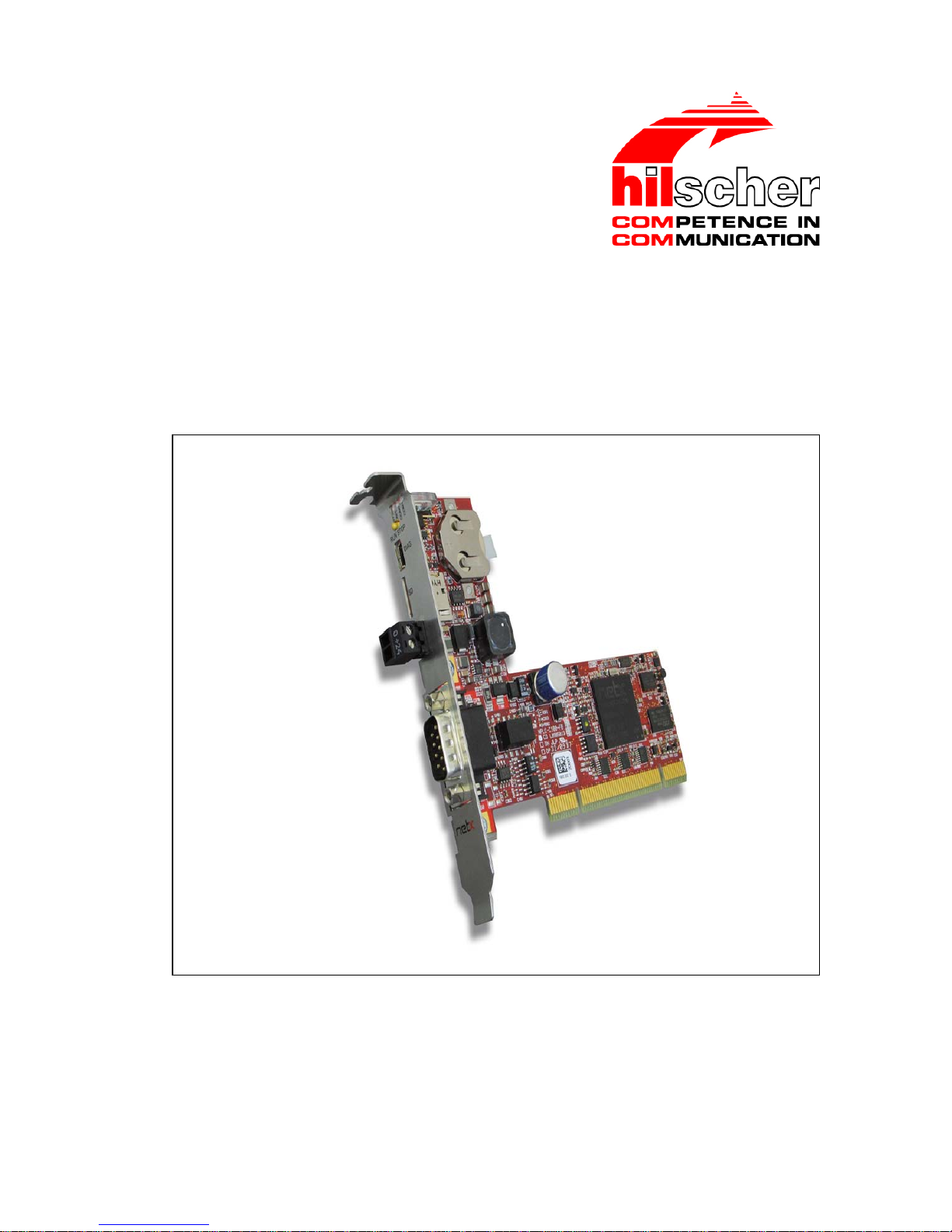
This user manual contains the description for the slot PLC NPLC-C100-xx.
NPLC-C100-xx are PC cards with PLC functionality.
This user manual describes the slot PLCs
NPLC-C100-DP
NPLC-C100-CO
NPLC-C100-DN
1.1.1 List of Revisions
Index Date Chapter Revisions
1 2012-05-22 all Created.
2 2014-01-23 10.4 Section Disposal of Waste Electronic Equipment updated.
Table 1: List of Revisions
Page 5
Introduction 5/36
Slot PLC NPLC-C100 | Hardware Installation
DOC120112UM02EN | Revision 2 | English | 2014-01 | Released | Public © Hilscher, 2009-2014
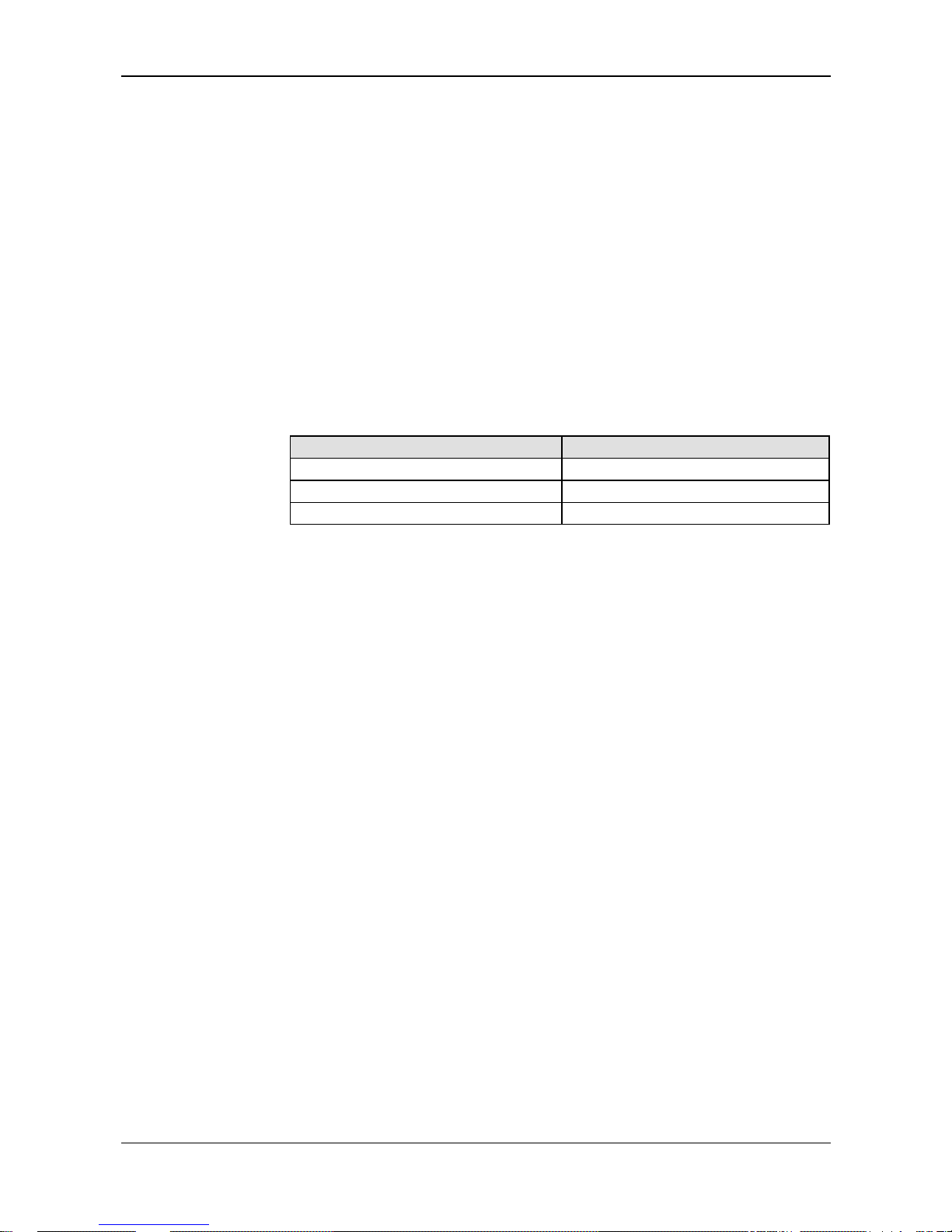
1.1.2 Reference to Hardware, Firmware, Driver and Software
Note: The listed hardware revision, firmware and driver versions
respectively versions of the programming software CoDeSys functionally
belong together.
Hardware
Hardware Part Number Bus Type Revision
NPLC-C100-DP 1800.410 PROFIBUS DP 4
NPLC-C100-CO 1800.500 CANopen 4
NPLC-C100-DN 1800.510 DeviceNet 4
Table 2: Reference to Hardware
The part number only is not enough to order the slot PLC. The product
variant must also be specified (which is the part after the slash “/”) to get a
slot PLC with the preloaded firmware containing the embedded PLC type.
Product Variant
Product PLC Type
Including PLC
Programming Software
NPLC-C100-DP/S7
S7 compatible PLC from
IBH Softec
-
NPLC-C100-DP/CDS-OPC
NPLC-C100-CO/CDS-OPC
NPLC-C100-DN/CDS-OPC
CoDeSys PLC from 3S CoDeSys
NPLC-C100-DP/CLR
ProConOS eCLR from
KW-Software
MULTIPROG Express
Table 3: Reference to Product Variant
Firmware
Each slot PLC of the product variants listed above is delivered with
preloaded firmware.
Driver
Driver Driver Type Driver Version
cifX Device Driver PC card driver for Windows 1.1.1.0
USB Driver USB driver for Windows 5.1.2600.2180
Table 4: Reference to Driver
Page 6
Introduction 6/36
Slot PLC NPLC-C100 | Hardware Installation
DOC120112UM02EN | Revision 2 | English | 2014-01 | Released | Public © Hilscher, 2009-2014
1.1.3 Conventions in this Manual
Operation instructions, a result of an operation step or notes are marked as
follows:
Operation Instructions:
<instruction>
or
1. <instruction>
2. <instruction>
Results:
<result>
Notes:
Important: <important note>
Note: <note>
<note, where to find further information>
Positions in Figures
The Positions
, , ... or , , ... or , , ... refer to the
figure used in that section. If the numbers reference to a section outside the
current section then a cross reference to that section and figure is
indicated.
Page 7

Introduction 7/36
Slot PLC NPLC-C100 | Hardware Installation
DOC120112UM02EN | Revision 2 | English | 2014-01 | Released | Public © Hilscher, 2009-2014
1.2 Legal Notes
1.2.1 Copyright
© Hilscher, 2009-2014, Hilscher Gesellschaft für Systemautomation mbH
All rights reserved.
The images, photographs and texts in the accompanying material (user
manual, accompanying texts, documentation, etc.) are protected by
German and international copyright law as well as international trade and
protection provisions. You are not authorized to duplicate these in whole or
in part using technical or mechanical methods (printing, photocopying or
other methods), to manipulate or transfer using electronic systems without
prior written consent. You are not permitted to make changes to copyright
notices, markings, trademarks or ownership declarations. The included
diagrams do not take the patent situation into account. The company
names and product descriptions included in this document may be
trademarks or brands of the respective owners and may be trademarked or
patented. Any form of further use requires the explicit consent of the
respective rights owner.
1.2.2 Important Notes
The user manual, accompanying texts and the documentation were created
for the use of the products by qualified experts, however, errors cannot be
ruled out. For this reason, no guarantee can be made and neither juristic
responsibility for erroneous information nor any liability can be assumed.
Descriptions, accompanying texts and documentation included in the user
manual do not present a guarantee nor any information about proper use
as stipulated in the contract or a warranted feature. It cannot be ruled out
that the user manual, the accompanying texts and the documentation do
not correspond exactly to the described features, standards or other data of
the delivered product. No warranty or guarantee regarding the correctness
or accuracy of the information is assumed.
We reserve the right to change our products and their specification as well
as related user manuals, accompanying texts and documentation at all
times and without advance notice, without obligation to report the change.
Changes will be included in future manuals and do not constitute any
obligations. There is no entitlement to revisions of delivered documents.
The manual delivered with the product applies.
Hilscher Gesellschaft für Systemautomation mbH is not liable under any
circumstances for direct, indirect, incidental or follow-on damage or loss of
earnings resulting from the use of the information contained in this
publication.
Page 8

Introduction 8/36
Slot PLC NPLC-C100 | Hardware Installation
DOC120112UM02EN | Revision 2 | English | 2014-01 | Released | Public © Hilscher, 2009-2014
1.2.3 Exclusion of Liability
The delivered product (including the technical data) is subject to export or
import laws as well as the associated regulations of different counters, in
particular those of Germany and the USA. The software may not be
exported to countries where this is prohibited by the United States Export
Administration Act and its additional provisions. You are obligated to
comply with the regulations at your personal responsibility. We wish to
inform you that you may require permission from state authorities to export,
re-export or import the product.
1.2.4 Warranty
Although the hardware and software was developed with utmost care and
tested intensively, Hilscher Gesellschaft für Systemautomation mbH does
not guarantee its suitability for any purpose not confirmed in writing. It
cannot be guaranteed that the hardware and software will meet your
requirements, that the use of the software operates without interruption and
that the software is free of errors. No guarantee is made regarding
infringements, violations of patents, rights of ownership or the freedom from
interference by third parties. No additional guarantees or assurances are
made regarding marketability, freedom of defect of title, integration or
usability for certain purposes unless they are required in accordance with
the law and cannot be limited. Warranty claims are limited to the right to
claim rectification.
Page 9

Introduction 9/36
Slot PLC NPLC-C100 | Hardware Installation
DOC120112UM02EN | Revision 2 | English | 2014-01 | Released | Public © Hilscher, 2009-2014
1.2.5 Export Regulations
The delivered product (including the technical data) is subject to export or
import laws as well as the associated regulations of different counters, in
particular those of Germany and the USA. The software may not be
exported to countries where this is prohibited by the United States Export
Administration Act and its additional provisions. You are obligated to
comply with the regulations at your personal responsibility. We wish to
inform you that you may require permission from state authorities to export,
re-export or import the product.
1.2.6 Registered Trademarks
Windows® XP, Windows® Vista, Windows® 7 are registered trademarks of
the Microsoft Corporation.
Adobe-Acrobat
®
is an registered trademark of the Adobe Systems
Incorporated.
1.3 Licenses
A license for the used PLC runtime (PLC type) is necessary to operate the
PLC runtime. This license is stored in the slot PLC hardware and included
in the scope of delivery of the ordered product variant. The license permits
the use and operation of the respective PLC runtime in the hardware.
A slot PLC is delivered with exactly one license which is stored in the
hardware. A license can’t be converted into another license. The license
can’t be used for another PLC type.
A license for fieldbus master functionality is necessary in the slot PLC to
operate on the fieldbus as master.
Page 10
Safety 10/36
Slot PLC NPLC-C100 | Hardware Installation
DOC120112UM02EN | Revision 2 | English | 2014-01 | Released | Public © Hilscher, 2009-2014
2 Safety
2.1 Safety Instructions
The user manual, the accompanying texts and the documentation are
written for the use of the products by educated personnel. When using the
products, all Safety Messages, Safety Messages, Property Damage
Messages and all valid legal regulations have to be obeyed. Technical
knowledge is presumed. The user has to assure that all legal regulations
are obeyed.
2.2 Intended Use
The slot PLC described in this user manual is a PC card with PLC
functionality and fieldbus communication. Depending from the loaded
firmware, the fieldbus systems listed in the following table can be realized
using the respective slot PLC.
Slot PLC Fieldbus System
NPLC-C100-DP PROFIBUS DP Master
NPLC-C100-CO CANopen Master
NPLC-C100-DN DeviceNet Master
Table 5: Slot PLC NPLC-C100 and Fieldbus Systems realized thereby
2.3 Personnel Qualification
The PC Card NPLC-C100 must only be installed, configured and removed
by qualified personnel. Job-specific technical skills for people professionally
working with electricity must be present concerning the following topics:
Safety and health at work
Mounting and connecting of electrical equipment
Measurement and Analysis of electrical functions and systems
Evaluation of the safety of electrical systems and equipment
Installing and Configuring IT systems
2.4 References Safety
[S1]
ANSI Z535.6-2006 American National Standard for Product Safety Information in
Product Manuals, Instructions, and Other Collateral Materials
[S2]
IEC 60950-1, Information technology equipment - Safety - Part 1: General
requirements, (IEC 60950-1:2005, modified); German Edition EN 60950-1:2006
[S3] EN 61340-5-1 and EN 61340-5-2 as well as IEC 61340-5-1 and IEC 61340-5-2
Page 11

Safety 11/36
Slot PLC NPLC-C100 | Hardware Installation
DOC120112UM02EN | Revision 2 | English | 2014-01 | Released | Public © Hilscher, 2009-2014
2.5 Commitment to read and understand the Manual
Important!
To avoid personal injury and to avoid property damage to your system
or to your device, you must read and understand all instructions in the
manual and all accompanying texts to your device, before installing and
operating your device.
First read the Safety Instructions in the safety chapter.
Obey to all Safety Messages in the manual.
Keep the product DVD providing the product manuals.
2.6 Safety Instructions to avoid Personal Injury
To ensure your own personal safety and to avoid personal injury, you
necessarily must read, understand and follow the following safety
instructions and safety messages in this manual about danger causing
personal injury, before you install and operate your NPLC-C100.
2.6.1 Electrical Shock Hazard
The danger of a lethal electrical shock caused by parts with more than 50V
may occur, if you open the PC cabinet to install the PC Card NPLC-C100.
HAZARDOUS VOLTAGE is present inside of the PC or of the connec-
ting device, into which the PC Card cifX is integrated. Strictly obey to all
safety rules provided by the device’s manufacturer in the documentation!
First disconnect the power plug of the PC or of the connecting device,
before you open the cabinet.
Make sure, that the power supply is off at the PC or at the connecting
device.
Open the PC cabinet and install or remove the PC Card NPLC-C100
only after disconnecting power.
An electrical shock is the result of a current flowing through the human
body. The resulting effect depends on the intensity and duration of the
current and on its path through the body. Currents in the range of
approximately ½ mA can cause effects in persons with good health, and
indirectly cause injuries resulting from startle responses. Higher currents
can cause more direct effects, such as burns, muscle spasms, or
ventricular fibrillation.
In dry conditions permanent voltages up to approximately 42.4 V peak or
60 V DC are not considered as dangerous, if the contact area is equivalent
to a human hand.
Reference Safety [S2]
Page 12

Safety 12/36
Slot PLC NPLC-C100 | Hardware Installation
DOC120112UM02EN | Revision 2 | English | 2014-01 | Released | Public © Hilscher, 2009-2014
2.7 Labeling of Safety Instructions
The Section Safety Messages at the beginning of a chapter are
pinpointed particularly. They are highlighted with a specific safety
symbol and a signal word according to the degree of endangerment.
Inside the safety message the danger is exactly named.
The Integrated Safety Messages within an instruction description are
highlighted with a signal word according to the degree of endangerment
and possibly by a principle symbol. Inside the safety message the
danger is exactly named.
Safety
Symbol
USA Sort of Warning or Principle
Warning of Personal Injury and Property Damage Message
USA: Warning of Personal Injury
As in the scope of the ANSI Z535 Standard (for USA) instructions to a property damage
message may not contain a warning triangle, this property damage messages are listed
separately for the USA.
Warning of Lethal Electrical Shock
Warning of Damages by Electrostatic Discharge
Principle: Disconnect the Power Plug
Table 6: Safety Symbols and Sort of Warning or Principle
Signal
Word
Meaning Meaning (USA)
Indicates a direct hazard with high risk, which
will have as consequence death or grievous
bodily harm if it isn't avoided.
Indicates a Hazardous Situation Which if not
Avoided, will Result in Death or Serious Injury.
Indicates a possible hazard with medium risk,
which will have as consequence death or
(grievous) bodily harm if it isn't avoided.
Indicates a Hazardous Situation Which if not
Avoided, could Result in Death or Serious
Injury.
Indicates a minor hazard with medium risk,
which could have as consequence simple
battery if it isn't avoided.
Indicates a Hazardous Situation Which if not
Avoided, may Result in Minor or Moderate
Injury.
Indicates a Property Damage Message. Indicates a Property Damage Message.
Note
Indicates an important note in the manual. Indicates an Important Note in the Manual.
Table 7: Signal Words
In this document all Safety Instructions and Safety Messages are designed
according both to the international used safety conventions as well as to
the ANSI Z535 standard, refer to reference safety [S1].
Page 13

Safety 13/36
Slot PLC NPLC-C100 | Hardware Installation
DOC120112UM02EN | Revision 2 | English | 2014-01 | Released | Public © Hilscher, 2009-2014
2.8 Safety Instructions
This manual contains instructions which must be observed to ensure your
own personal safety and to avoid damage to devices.
2.8.1 Electrical Shock Hazard
Electrical Shock Hazard
HAZARDOUS VOLTAGE inside of the PC or of the connecting device.
Therefore first disconnect the power plug of the PC or of the connecting
device.
Make sure, that the power supply is off at the PC or at the connecting
device.
Open the PC cabinet and install or remove the slot PLC only after
disconnecting power.
2.9 Property Damage Messages
This manual contains instructions which must must be red, understod and
observed to avoid damage to devices.
2.9.1 Electrostatically sensitive Devices
Adhere to the necessary safety precautions for components that are
vulnerable with electrostatic discharge (EN 61340-5-1 and EN 61340-5-2
as well as IEC 61340-5-1 and IEC 61340-5-2).
Electrostatically sensitive Devices
This equipment is sensitive to electrostatic discharge, which cause
internal damage and affect normal operation. Follow guidelines when you
handle this equipment.
Observe the necessary safety precautions when handling components
that are vulnerable to electrostatic discharge.
Page 14

Description and Requirements 14/36
Slot PLC NPLC-C100 | Hardware Installation
DOC120112UM02EN | Revision 2 | English | 2014-01 | Released | Public © Hilscher, 2009-2014
3 Description and Requirements
3.1 Description
The slot PLC NPLC-C100 described in this user manual is a PC card with
PLC functionality and fieldbus communication. Depending from the loaded
firmware, the fieldbus systems listed in Table 5: Slot PLC NPLC-C100 and
Fieldbus Systems realized thereby on page 10 can be realized.
Pow
er Supply
The slot PLC NPLC-C100 can be supplied by 5 V or 3.3 V (via the PCI bus)
or by an external supply voltage of 24 V DC. By that a redundant power
supply is achieved.
Additionally the slot PLC NPLC-C100 can be used with a battery that in
case of loss of power supplies power to the real time clock and to the
SRAM circuit (for remanent data of the PLC) of the PLC.
The supply voltage of the slot PLC and the battery charge condition can be
monitored within the PLC program by monitoring functions.
This slot PLC is a PC card for fieldbus communication and handles the
complete data exchange between the connected fieldbus devices and the
PLC program.
In one PC a maximum of two slot PLCs can be used.
Page 15

Description and Requirements 15/36
Slot PLC NPLC-C100 | Hardware Installation
DOC120112UM02EN | Revision 2 | English | 2014-01 | Released | Public © Hilscher, 2009-2014
3.2 System Requirements
3.2.1 System Requirements PC
Windows® XP, Windows® 7
PC with PCI connector with 3,3 V or 5 V for hardware revision 4 of
“NPLC C100-xx“
DVD ROM drive
Graphic resolution: min. 1024 x 768 pixel or higher
Keyboard and Mouse
3.3 Requirements for Operation
Note: For operating a slot PLC NPLC-C100-xx
Update older versions of the cifX Device Driver to V1.1.1.0.
3.3.1 Slot PLC NPLC-C100-XX
The following requirements must be fulfilled for operation of the slot PLC
with a master functionality:
Firmware
A suitable firmware (for the PLC type) has to be loaded.
License
The slot PLC was ordered with the right and necessary licenses.
Configuration
Die slot PLC must be configured using the configuration software.
Programming The PLC program must be created with the PLC programming
software and loaded into the slot PLC.
Communication For communication slave devices for the used communication
system are required.
Table 8: Requirements for Operation of the Slot PLC
Page 16

Device Drawings 16/36
Slot PLC NPLC-C100 | Hardware Installation
DOC120112UM02EN | Revision 2 | English | 2014-01 | Released | Public © Hilscher, 2009-2014
4 Device Drawings
4.1 Device Drawing NPLC-C100-DP
Figure 1: Device Drawing NPLC-C100-xx
Number Designation
1 LED SYS
2 LED APL
3 LED COM0
4 LED COM1
5 RUN/STOP Switch
6 DIAG – USB Diagnostic Interface
7 Slot for Memory Card
8 MicroSD Memory Card
9 External Power Supply
10 Fieldbus interface
NPLC-C100-DP: PROFIBUS interface
NPLC-C100-CO: CANopen interface
NPLC-C100-DN: DeviceNet interface
11 Battery holder
12 Battery
Table 9: Designation in the Device Drawing NPLC-C100-xx
Page 17

Device Drawings 17/36
Slot PLC NPLC-C100 | Hardware Installation
DOC120112UM02EN | Revision 2 | English | 2014-01 | Released | Public © Hilscher, 2009-2014
4.1.1 Cover NPLC-C100-xx
NPLC-C100-DN NPLC-C100-DP / NPLC-C100-CO No. Designation
LED SYS
LED APL
LED COM0
LED COM1
RUN/STOP Switch
DIAG – USB Diagnostic
Interface
Slot for Memory Card
MicroSD Memory Card
External Power Supply
Fieldbus interface
-DP – D-Sub female, 9 pin
-CO – D-Sub male, 9 pin
-DN – COMBICON, 5 pin
Table 10: Designation for the Cover of NPLC-C100-xx
Page 18

Installing Hardware (Slot PLC) 18/36
Slot PLC NPLC-C100 | Hardware Installation
DOC120112UM02EN | Revision 2 | English | 2014-01 | Released | Public © Hilscher, 2009-2014
5 Installing Hardware (Slot PLC)
5.1 Safety Messages on Personal Injury
Obey to the following safety messages on personal injury, when installing,
uninstalling or replacing the slot PLC NPLC-C100.
5.2 Safety Advices
Obey to the following safety advices, when installing the slot PLC.
Lethal Electrical Shock caused by parts with more than 50V!
HAZARDOUS VOLTAGE inside of the PC or of the connecting device.
Strictly obey to all safety rules provided by the device’s manufacturer in
the documentation!
First disconnect the power plug of the PC or of the connecting device,
before you open the cabinet.
Make sure, that the power supply is off at the PC or at the connecting
device.
Open the PC cabinet and install or remove the slot PLC NPLC-C100
only after disconnecting power
Page 19

Installing Hardware (Slot PLC) 19/36
Slot PLC NPLC-C100 | Hardware Installation
DOC120112UM02EN | Revision 2 | English | 2014-01 | Released | Public © Hilscher, 2009-2014
5.3 Property Damage Messages
Obey to the following property damage messages, when installing,
uninstalling or replacing the slot PLC NPLC-C100.
5.3.1 Device Destruction by exceeding allowed Supply Voltage
Adhere for all slot PLC NPLC-C100 described in this manual the instruction
hereafter:
Device Destruction!
Use only the permissible supply voltage to operate the slot PLC NPLC-
C100.
Operating the slot PLC NPLC-C100 with a supply voltage above of the
specified range leads to device destruction.
5.3.2 Device Destruction by exceeding allowed Signaling Voltage
Adhere for all slot PLC NPLC-C100 described in this manual the instruction
hereafter:
Device Destruction!
All I/O signal pins at the slot PLC NPLC-C100 tolerate only a specified
signaling voltage!
Operation the slot PLC NPLC-C100 with a signaling voltage other than
the specified signaling voltage may lead to severe damage to the slot
PLC NPLC-C100!
For detailed information on the supply and signaling voltage of the slot PLC
NPLC-C100 described in this manual, refer to section Technical Data Slot
PLC NPL
C-C100-xx on page 29.
5.3.3 Electrostatically sensitive Devices
Adhere to the necessary safety precautions for components that are
vulnerable with electrostatic discharge.
Electrostatically sensitive Devices
To prevent damage to the PC and the slot PLC NPLC-C100, make sure,
that the slot PLC NPLC-C100 is grounded via the endplate and the PC
and make sure, that you are discharged when you install/uninstall the
slot PLC NPLC-C100.
Page 20

Installing Hardware (Slot PLC) 20/36
Slot PLC NPLC-C100 | Hardware Installation
DOC120112UM02EN | Revision 2 | English | 2014-01 | Released | Public © Hilscher, 2009-2014
5.4 Installing Battery
With delivery a protection foil protects the battery against discharge.
Remove protection foil
Remove the protection foil to activate the battery buffering.
5.5 Installing Slot PLC NPLC-C100-xx
Note: Install all software components, before you install the hardware, to
prevent problems due to missing drivers after rebooting the PC.
For installation of the slot PLC NPLC-C100 handle as follows:
1. Disconnect the power plug of the PC.
2. Open the cabinet of the PC.
3. Plug in the slot PLC on a free PCI slot
4. Fix the slot PLC using the hole intended.
5. Close the PC casing.
6. Connect the external 24 V power supply, if needed.
7. Connect the PC to the power supply and switch on the PC.
Page 21

Hardware 21/36
Slot PLC NPLC-C100 | Hardware Installation
DOC120112UM02EN | Revision 2 | English | 2014-01 | Released | Public © Hilscher, 2009-2014
6 Hardware
6.1 Block Diagram
Figure 2: NPLC-C100-xx Block Diagram
Page 22

Hardware 22/36
Slot PLC NPLC-C100 | Hardware Installation
DOC120112UM02EN | Revision 2 | English | 2014-01 | Released | Public © Hilscher, 2009-2014
6.2 Internal and External Power Supply
Note: Hardware revision 3 of the slot PLC NPLC-C100 can be supplied
via the PCI bus only with 5 V. Hardware revision 4 of the slot PLC NPLCC100 can be supplied via the PCI bus with 3.3 V respectively 5 V.
The slot PLC can be supplied by 5 V or 3.3 V (via PCI) or by an additional
external supply voltage of 24 VDC. The permitted voltage range for external
powering is 18 … 30 V. If the external supply voltage reaches a level below
13 V, then the supply of the slot PLC from the external supply voltage is
switched off.
6.3 Reset Behaviour
The slot PLC has no connection via the PCI bus to the PC reset signal.
This means that a reset of the PC for example when using the front panel
reset button of the computer does not influence the slot PLC behavior.
The PowerOn reset will be served from both power sources (internal und
external).
6.4 RUN/STOP Switch
The PLC program’s operating condition in the slot PLC can be changed
using the switch at the front of the slot PLC and may get the status.
Position Function
RUN
The loaded PLC program is executed cyclically.
STOP The cyclic execution of the PLC program is stopped. Loa ding a new PLC
program or a firmware update is possible in this state.
Table 11: RUN/STOP Switch
6.5 LEDs
The meaning of the LED signals depends on the used firmware and the
embedded PLC type.
For a firmware with CoDeSys: The meaning of the LED is described in the
manual ‚netPLC with CoDeSys, commissioning’.
Page 23

Hardware 23/36
Slot PLC NPLC-C100 | Hardware Installation
DOC120112UM02EN | Revision 2 | English | 2014-01 | Released | Public © Hilscher, 2009-2014
6.6 Interfaces
6.6.1 CANopen Interface
Slot PLC NPLC-C100-CO:
CANopen Pin Assignment
CANopen Pin Signal Description
2 CAN L CAN Low bus line
3
ISO
GND
CAN ground
7 CAN H CAN High bus line
1, 4, 5,
6, 8, 9
Important note and strongly
recommended: Leave these pins
unconnected! Otherwise there is
a high risk of a device damage.
9-pole
sub-D male.
Shield PE Metal shell on PE
Table 12: CANopen Pin Assignment
Position in Figure 1 on page 16.
6.6.2 DeviceNet Interface
Slot PLC NPLC-C100-DN:
DeviceNet Pin Assignment
DeviceNet Pin Signal Description
1 ISO GND Common ground
DeviceNet-power supply.
2 CAN L CAN Low signal
3 Drain Shield
4 CAN H CAN High signal
COMBICON
Socket, female
5 V+ +24 V DeviceNet-power supply
Table 13: DeviceNet Pin Assignment
Position in Figure 1 on page 16.
Page 24

Hardware 24/36
Slot PLC NPLC-C100 | Hardware Installation
DOC120112UM02EN | Revision 2 | English | 2014-01 | Released | Public © Hilscher, 2009-2014
6.6.3 PROFIBUS Interface
Slot PLC NPLC-C100-DP:
RS-485 PROFIBUS Pin Assignment
PROFIBUS Pin Signal Description
3 Rx/Tx + Receive- / Transmit data positive
4 CNTR-P Control signal for repeater (direction control)
5 ISO GND Data ground
6 VP Power supply positive
9-pole sub-D
socket,
female
8 Rx/Tx - Receive- / Transmit data negative
Table 14: PROFIBUS RS-485 Pin Assignment
Position in Figure 1 on page 16.
6.6.4 Mini-B USB Connector (5 Pin)
USB Buchse Pin Signal Beschreibung
1 -
2 D- Data 3 D+ Data +
4 ID
5 GND Ground
Schirm PE Metallschutzkragen auf PE
Tabelle 1: Mini-B USB Anschluss Pinbelegung (5-polig)
Position in Figure 1 on page 16.
Page 25

Battery 25/36
Slot PLC NPLC-C100 | Hardware Installation
DOC120112UM02EN | Revision 2 | English | 2014-01 | Released | Public © Hilscher, 2009-2014
7 Battery
The battery has the type CR2032.
Using the Battery is optional.
The battery is used for
buffering the real time clock and
buffering of remanent data.
The PLC program is normally not buffered by the battery. The PLC program
is stored remanently in the FLASH memory of the slot PLC. The operation
to store the PLC program remanently has to be activated manually.
A fully charged battery has a life time of 1 year.
If the slot PLC is powered then the battery is not discharged.
Important: Recommendation: Change the battery every 12 month.
Page 26

Battery 26/36
Slot PLC NPLC-C100 | Hardware Installation
DOC120112UM02EN | Revision 2 | English | 2014-01 | Released | Public © Hilscher, 2009-2014
7.1 Preparation for changing Battery
7.1.1 Safety Messages on Personal Injury
Obey to the following safety messages on personal injury, when installing,
uninstalling or replacing the slot PLC NPLC-C100.
7.1.1.1 Electrical Shock Hazard
Lethal Electrical Shock caused by parts with more than 50V!
HAZARDOUS VOLTAGE inside of the PC or of the connecting device.
Strictly obey to all safety rules provided by the device’s manufacturer in
the documentation!
First disconnect the power plug of the PC or of the connecting device,
before you open the cabinet.
Make sure, that the power supply is off at the PC or at the connecting
device.
Open the PC cabinet and install or remove the slot PLC NPLC-C100 only
after disconnecting power.
7.2 Changing the Battery
1. Pull off the power plug of your PC.
2. Open the housing of your PC.
3. Unmount the slot PLC
4. Pull out the slot PLC from the card slot of your PC.
5. Remove battery
To remove the battery from its battery holder move it sidewards
Page 27

Battery 27/36
Slot PLC NPLC-C100 | Hardware Installation
DOC120112UM02EN | Revision 2 | English | 2014-01 | Released | Public © Hilscher, 2009-2014
6. Insert Battery
Use a fully charged battery.
Pay attention to the polarity of the battery. In the picture below the
positive pole is on top.
To insert the battery shift it under control of the correct polarity into the
battery holder.
7. Plug in the slot PLC into a free PCI card slot.
8. Fix the slot PLC at the designated drilling hole.
9. Close the PC housing.
10. Reconnect the PC to the mains power and switch it on.
For battery disposal see section Battery Disposal on page 34.
Page 28

Troubleshooting 28/36
Slot PLC NPLC-C100 | Hardware Installation
DOC120112UM02EN | Revision 2 | English | 2014-01 | Released | Public © Hilscher, 2009-2014
8 Troubleshooting
General
Check, if the requirements for slot PLC operation are fulfilled.
Further information to this you find in section System Requirements on
page 15.
Cable
Check that the pin assignment of the used cable is correct.
Configuration
Check the configuration in the Master and the Slave device. The
configuration has to match.
Page 29

Technical Data Slot PLC NPLC-C100-xx 29/36
Slot PLC NPLC-C100 | Hardware Installation
DOC120112UM02EN | Revision 2 | English | 2014-01 | Released | Public © Hilscher, 2009-2014
9 Technical Data Slot PLC NPLC-C100-xx
Number of Slot PLCs
Max. 2 slot PLC in one PC
Table 15: Technical Data Slot PLC
Item
NPLC-C100-DP, NPLC-C100-CO, NPLC-C100-DN
System Interface
PCI V2.3, 33 MHz
Dual-Port Memory Size
64 KByte
Protocols
NPLC-C100-DP, PROFIBUS DP Master
NPLC-C100-CO, CANopen Master
NPLC-C100-DN, DeviceNet Master
Processor
netX 100
Memory
8 MByte SDRAM,
128 KByte SRAM (Battery buffering),
4 MByte serial Flash
LED
SYS, APL, COM0, COM1
Operating Elements
RUN/STOP switch
Battery Type
CR 2032
Memory Card
microSD
PROFIBUS Interface
NPLC-C100-DP
D-Sub female connector, 9 pin;
optically isolated RS-485 interface for PROFIBUS DP
NPLC-C100-CO
D-Sub male connector, 9 pin for CANopen
NPLC-C100-DN
COMBICON, 5 pin for DeviceNet
Connection for
external Power Supply
COMBICON 2-pin
Diagnostic Interface
Mini USB
Power Supply Rev 3:
5 V (4,5 … 5,5 V), 500 mA
Rev 4:
PCI-Bus 3,3 V (3,1 … 3,5 V), 700 mA or
5 V (4,5 … 5,5 V), 500 mA or
External: 18 … 30 VDC
Current consumption at 18 V approx. 120 mA,
at 30 V approx. 80 mA.
The current is taken from the highest supply voltage.
External Power Supply
18 … 30 VDC
Dimensions (L x W x D)
120 x 90 x 20 mm
(130 x 121 x 22 mm over all)
Operating Temperatur
0 … 55 °C
Table 16: Technical Data NPLC-C100-xx
Page 30

Appendix 30/36
Slot PLC NPLC-C100 | Hardware Installation
DOC120112UM02EN | Revision 2 | English | 2014-01 | Released | Public © Hilscher, 2009-2014
10 Appendix
10.1 Memory Card
The slot PLC “NPLC-C100” device can be set back to factory settings with
a micro SD card and the base firmware on it.
Requirements
The memory card can have up to 4 GB storage capacity.
The memory card must be formatted in the FAT16 format (no FAT32).
The HDSC format is not supported.
Preparation
Copy all files from the directory
"Firmware\...\Memory Card Image"
including the file STARTUP.INI and the directory BACKUP and all
subdirectories onto an empty micro SD card to the card's root directory.
Procedure
1. Have the SD card ready with the copied image
2. Power down the PC with the slot PLC inserted. If used, switch off the
external power supply.
3. Insert the card into the SD card slot till it clicks into place
4. Re-Power the PC
The device loads the base firmware and indicates this by the following
states of the SYS LED: Fast change between green and yellow (fo
r
appr. 8 s), then yellow on (for appr. 10 s), then off for a short moment
and finally it turns to green on.
The device then has factory settings.
5. Remove the SD card from the SD card slot
Page 31

Appendix 31/36
Slot PLC NPLC-C100 | Hardware Installation
DOC120112UM02EN | Revision 2 | English | 2014-01 | Released | Public © Hilscher, 2009-2014
10.2 Update Firmware
This section describes how the firmware of the slot PLC is updated.
1. Exit programs
Exit all programs that access to the slot PLC.
2. Open from the control panel the cifX Setup Program
Open the Control Panel with Start > Control Panel
open the program cifX Setup with a double click on the cifX Setup
symbol
The cifx Driver Setup Program is started
Page 32

Appendix 32/36
Slot PLC NPLC-C100 | Hardware Installation
DOC120112UM02EN | Revision 2 | English | 2014-01 | Released | Public © Hilscher, 2009-2014
3. Select CH#0
Select in the Device List tree under Active Devices at cifX (cifX0,
cifX1, …) entry CH#0.
4. Select firmware file
Open in the area Assigned Module/Firmware Files
with a click on
Add
the windows for the firmware file selection
Select the firmware file for the NPLC-C100 as listed in the document
“software installation” of the used PLC type.
Page 33

Appendix 33/36
Slot PLC NPLC-C100 | Hardware Installation
DOC120112UM02EN | Revision 2 | English | 2014-01 | Released | Public © Hilscher, 2009-2014
5. Provide firmware file for download
Click on Open
The firmware file is shown below Assigned Module/Firmware Files
6. Start firmware download
Click on Apply.
Answer the question
with Yes to start the firmware download.
The firmware file is loaded into the slot PLC
7 Reset of the slot PLC NPLC-C100
The slot PLC NPLC-C100 requires a reset.
Therefore shut down and power down the PC
If the external power supply is used, then switch off or disconnect the
external power supply from the slot PLC NPLC-C100.
Switch on the PC and if required switch on the external power supply.
The slot PLC NPLC-C100 does a reset.
Page 34

Appendix 34/36
Slot PLC NPLC-C100 | Hardware Installation
DOC120112UM02EN | Revision 2 | English | 2014-01 | Released | Public © Hilscher, 2009-2014
10.3 Battery Disposal
Important note from the European Directive 2006/66/EC on waste
accumulators and batteries:
Important: Batteries are not allowed to be thrown into the domestic
refuse. As a end user you are legally bound to return batteries to collecting
points or back to their origin.
Products containing batteries are marked with a crossed wheelie bin
symbol:
Figure 3: Labeling Batteries
Beneath the symbol you will find also a chemical symbol added for a
particular metal if the battery contains more than a specific percentage of it.
The chemical symbols Cd stands for Cadmium, Hg for mercury and Pb for
lead. Those are pollutants the environment never shall be contaminated
with.
10.4 Disposal of Waste Electronic Equipment
According to the European Directive 2002/96/EG “Waste Electrical and
Electronic Equipment (WEEE)”, waste electronic equipment may not be
disposed of as household waste. As a consumer, you are legally obliged to
dispose of all waste electronic equipment according to national and local
regulations.
Waste Electronic Equipment
This product must not be treated as household waste.
This product must be disposed of at a designated waste electronic
equipment collecting point.
Page 35

Appendix 35/36
Slot PLC NPLC-C100 | Hardware Installation
DOC120112UM02EN | Revision 2 | English | 2014-01 | Released | Public © Hilscher, 2009-2014
10.5 List of Figures
Figure 1: Device Drawing NPLC-C100-xx 16
Figure 2: NPLC-C100-xx Block Diagram 21
Figure 3: Labeling Batteries 34
10.6 List of Tables
Table 1: List of Revisions 4
Table 2: Reference to Hardware 5
Table 3: Reference to Product Variant 5
Table 4: Reference to Driver 5
Table 5: Slot PLC NPLC-C100 and Fieldbus Systems realized thereby 10
Table 6: Safety Symbols and Sort of Warning or Principle 12
Table 7: Signal Words 12
Table 8: Requirements for Operation of the Slot PLC 15
Table 9: Designation in the Device Drawing NPLC-C100-xx 16
Table 10: Designation for the Cover of NPLC-C100-xx 17
Table 11: RUN/STOP Switch 22
Table 12: CANopen Pin Assignment 23
Table 13: DeviceNet Pin Assignment 23
Table 14: PROFIBUS RS-485 Pin Assignment 24
Table 15: Technical Data Slot PLC 29
Table 16: Technical Data NPLC-C100-xx 29
Page 36

Appendix 36/36
Slot PLC NPLC-C100 | Hardware Installation
DOC120112UM02EN | Revision 2 | English | 2014-01 | Released | Public © Hilscher, 2009-2014
10.7 Contacts
Headquarters
Germany
Hilscher Gesellschaft für
Systemautomation mbH
Rheinstrasse 15
65795 Hattersheim
Phone: +49 (0) 6190 9907-0
Fax: +49 (0) 6190 9907-50
E-Mail: info@hilscher.com
Support
Phone: +49 (0) 6190 9907-99
E-Mail: de.support@hilscher.com
Subsidiaries
China
Hilscher Systemautomation (Shanghai) Co. Ltd.
200010 Shanghai
Phone: +86 (0) 21-6355-5161
E-Mail: info@hilscher.cn
Support
Phone: +86 (0) 21-6355-5161
E-Mail: cn.support@hilscher.com
France
Hilscher France S.a.r.l.
69500 Bron
Phone: +33 (0) 4 72 37 98 40
E-Mail: info@hilscher.fr
Support
Phone: +33 (0) 4 72 37 98 40
E-Mail: fr.support@hilscher.com
India
Hilscher India Pvt. Ltd.
New Delhi - 110 065
Phone: +91 11 26915430
E-Mail: info@hilscher.in
Italy
Hilscher Italia S.r.l.
20090 Vimodrone (MI)
Phone: +39 02 25007068
E-Mail: info@hilscher.it
Support
Phone: +39 02 25007068
E-Mail: it.support@hilscher.com
Japan
Hilscher Japan KK
Tokyo, 160-0022
Phone: +81 (0) 3-5362-0521
E-Mail: info@hilscher.jp
Support
Phone: +81 (0) 3-5362-0521
E-Mail: jp.support@hilscher.com
Korea
Hilscher Korea Inc.
Seongnam, Gyeonggi, 463-400
Phone: +82 (0) 31-789-3715
E-Mail: info@hilscher.kr
Switzerland
Hilscher Swiss GmbH
4500 Solothurn
Phone: +41 (0) 32 623 6633
E-Mail: info@hilscher.ch
Support
Phone: +49 (0) 6190 9907-99
E-Mail: ch.support@hilscher.com
USA
Hilscher North America, Inc.
Lisle, IL 60532
Phone: +1 630-505-5301
E-Mail: info@hilscher.us
Support
Phone: +1 630-505-5301
E-Mail: us.support@hilscher.com
 Loading...