

hilscher NOIT-E-NPI3-51-EN-RE User Manual

User manual
netPI
NOIT-E-NPI3-51-EN-RE
Hilscher Gesellschaft für Systemautomation mbH
www.hilscher.com
DOC170801UM01EN | Revision 1 | English | 2017-09 | Released | Public

Table of contents 2/64
Table of contents
1 Introduction .............................................................................................................................. 4
1.1 About the user manual .....................................................................................................4
1.2 List of revisions ................................................................................................................4
1.3 Further sources of information .........................................................................................4
2 Brief description ...................................................................................................................... 5
3 Device drawings....................................................................................................................... 6
3.1 Positions of the interfaces ................................................................................................6
3.2 Dimensions ......................................................................................................................8
4 Connectors and mounting ...................................................................................................... 9
4.1 Mounting ..........................................................................................................................9
4.2 Power supply....................................................................................................................9
4.3 LAN connectors................................................................................................................9
4.4 Real-Time Ethernet connectors .......................................................................................9
4.5 USB connectors ...............................................................................................................9
4.6 Wi-Fi...............................................................................................................................10
4.7 HDMI connector .............................................................................................................10
4.8 Slot for expansion modules............................................................................................10
5 LEDs........................................................................................................................................11
5.1 Positions of the LEDs on the gateway ...........................................................................11
5.2 Gateway status LEDs.....................................................................................................12
5.3 LEDs of the LAN interface..............................................................................................13
5.4 LEDs of the PROFINET IO Device interface..................................................................14
5.5 LEDs der EtherCAT Slave interface...............................................................................15
5.6 LEDs of the EtherNet/IP Adapter interface ....................................................................16
6 Commissioning the Edge Gateway ...................................................................................... 17
6.1 Establishing the IP address communication ..................................................................17
6.2 Using the web browser to establish a connection with the Edge Gateway ....................18
6.2.1 Using the host name ....................................................................................... 18
6.2.2 Access to the Edge Gateway in the Windows network environment .............. 19
7 Edge Gateway manager ........................................................................................................ 20
7.1 Calling the Edge Gateway Manager ..............................................................................20
7.2 Edge Gateway manager web page................................................................................21
8 Control Panel.......................................................................................................................... 22
8.1 Opening the control panel ..............................................................................................22
8.1.1 First login ........................................................................................................ 23
8.1.2 Secure connection .......................................................................................... 24
8.2 Control Panel commands...............................................................................................28
8.2.1 Overview and main menu ............................................................................... 28
8.2.2 System information and system time .............................................................. 29
8.2.3 Packet management ....................................................................................... 34
netPI | NOIT-E-NPI3-51-EN-RE
DOC170801UM01EN | Revision 1 | English | 2017-09 | Released | Public
© Hilscher 2017

Table of contents 3/64
8.2.4 Network........................................................................................................... 35
8.2.5 Services .......................................................................................................... 37
8.2.6 User management .......................................................................................... 38
8.2.7 Security certificates......................................................................................... 41
8.2.8 Help................................................................................................................. 44
8.2.9 Session ........................................................................................................... 44
9 Isolated application execution with Docker ........................................................................ 46
9.1 Docker, image, and container ........................................................................................46
9.2 Container for netPI: Examples .......................................................................................48
9.3 Working with Docker via the web GUI............................................................................49
9.3.1 The portainer.io interface ................................................................................ 49
9.3.2 Example: Executing the web server NGINX as a container............................ 52
10 Technical data ........................................................................................................................ 54
10.1 Technical data NIOT-E-NPI3-51-EN-RE........................................................................54
11 FCC authorization .................................................................................................................. 56
12 Decommissioning, dismounting and disposal ................................................................... 57
12.1 Putting the device out of operation.................................................................................57
12.2 Removing device from top hat rail..................................................................................57
12.3 Disposal of waste electronic equipment.........................................................................57
13 Appendix................................................................................................................................. 58
13.1 Legal notes.....................................................................................................................58
List of figures ......................................................................................................................... 62
List of tables........................................................................................................................... 63
Contacts.................................................................................................................................. 64
netPI | NOIT-E-NPI3-51-EN-RE
DOC170801UM01EN | Revision 1 | English | 2017-09 | Released | Public
© Hilscher 2017
Introduction 4/64
1 Introduction
1.1 About the user manual
This user manual describes the installation, configuration and functionality
of the device NIOT-E-NPI3-51-RE-EN.
In this description, the device NIOT-E-NPI3-51-RE-EN is named netPI and
Edge Gateway likewise. The name netPI is in reference to the Raspberry
Pi function and Egde Gateway is in reference to the use on the "Edge"
between the IT network and the OT network.
1.2 List of revisions
Revision Date Author Change
1 2017-09-18 HH, RG All sections created.
Table1: List of revisions
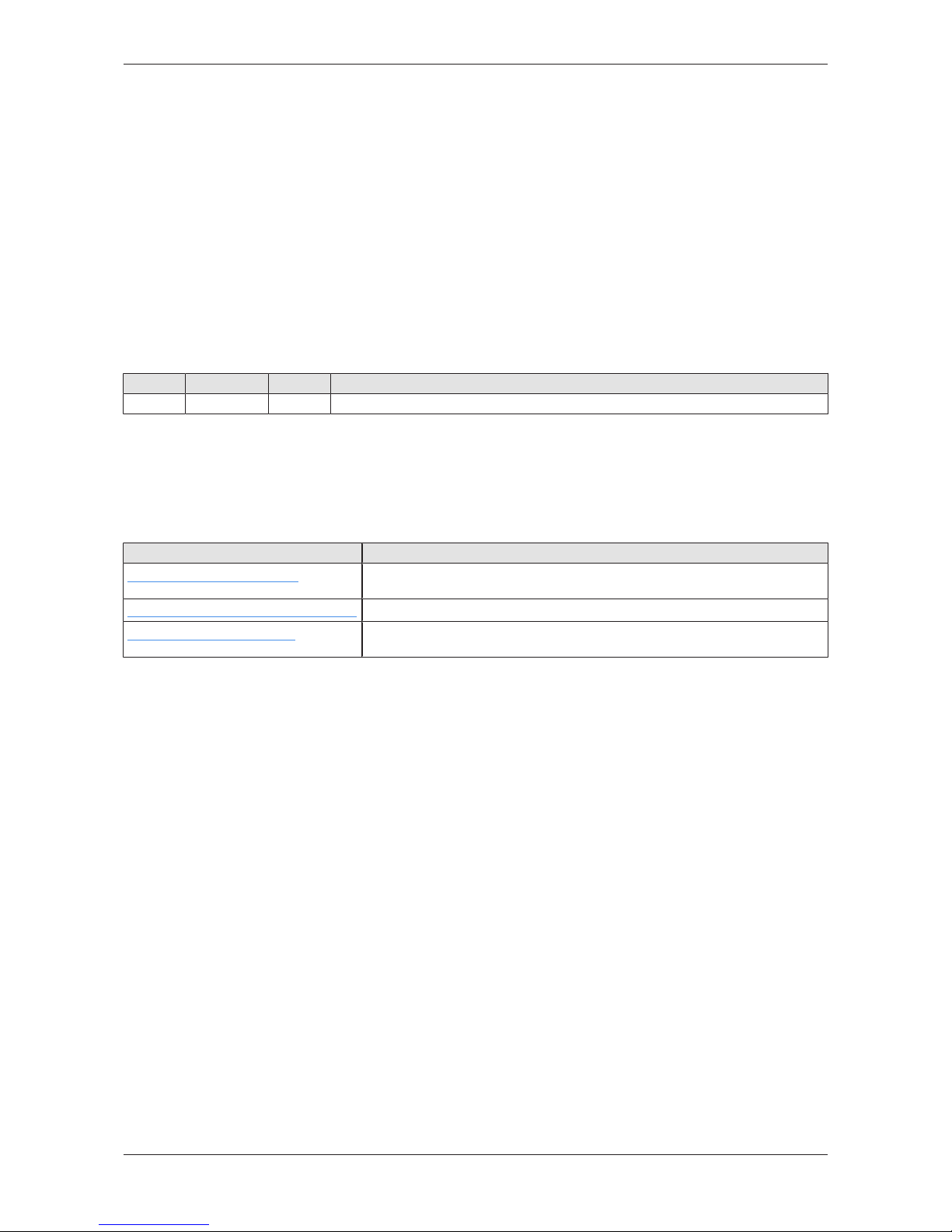
1.3 Further sources of information
The following table lists web addresses where you can get further
information for netPI.
Web address This site offers you
https://www.netiot.com/netPI
Product presentation, documentation, tutorials, informationen on expansion
modules, blog, FAQ, and forum on netPI and IIoT.
https://hub.docker.com/r/hilschernetpi/
Docker hub with example images for netPI.
https://www.raspberrypi.org/
Information, blog, downloads, community, forum, and education on Raspberry
Pi.
Table2: Further information
netPI | NOIT-E-NPI3-51-EN-RE
DOC170801UM01EN | Revision 1 | English | 2017-09 | Released | Public
© Hilscher 2017
Brief description 5/64
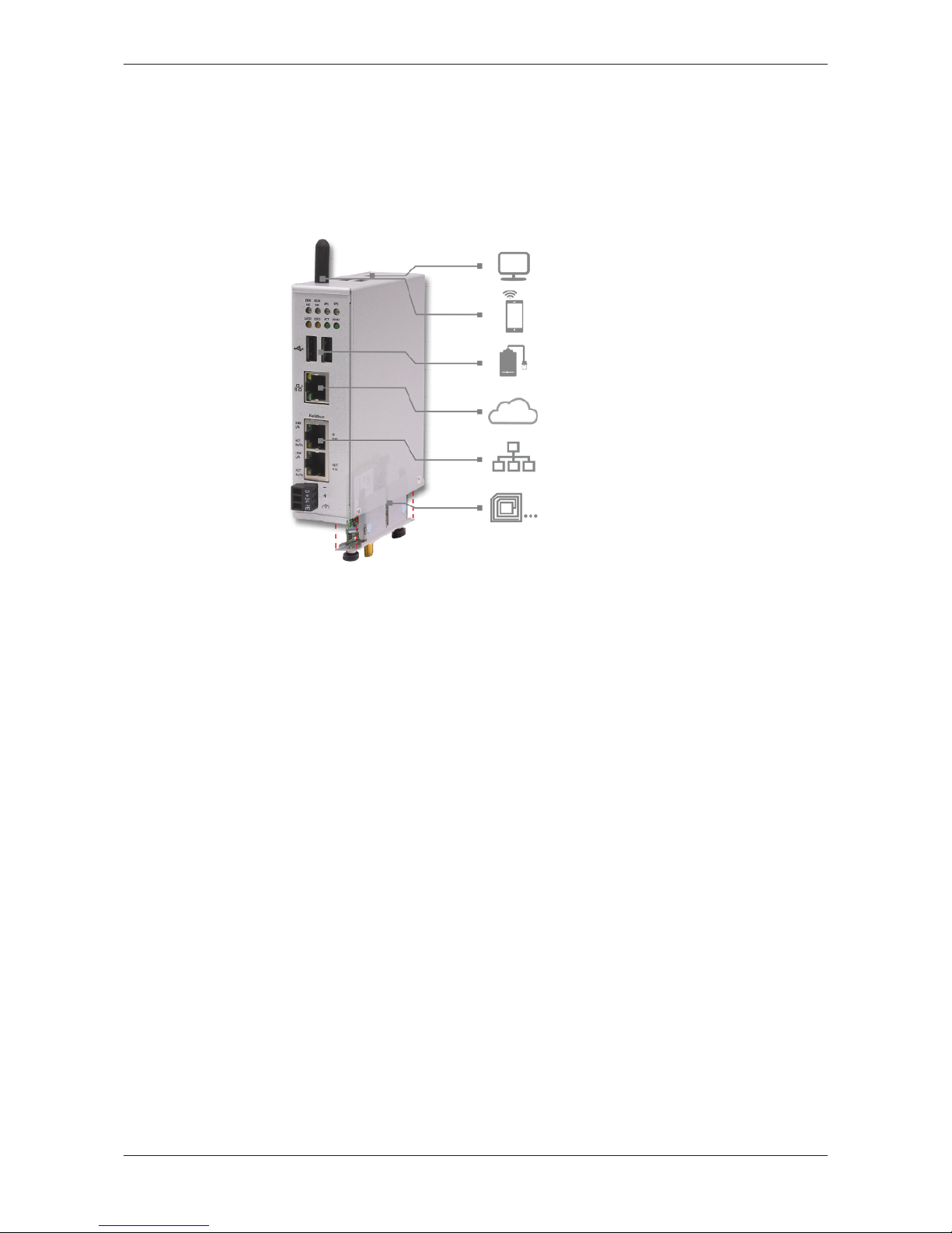
2 Brief description
netPI is a Raspberry Pi 3 architecture based platform for implementing
Cloud, Internet of Things and Industry 4.0 customized Edge Automation
projects safely. The device contains the original Raspberry Pi 3 circuitry
along with Hilscher’s multiprotocol chip netX and thus supports popular
Real-Time Ethernet networks.
Figure1: netPI
netPI was specifically designed for applications on the "Edge" between the
IT network and the OT network and therefore is a programmable Edge
Gateway. The LAN interface connects to the IT network and is the interface
for the device configuration via a web browser. The two additional Ethernet
interfaces connect the device to the Real-Time Ethernet network (OT
network). With the WiFi antenna, the device supports also wireless network
communication.
To expand the functional range of the device a slot for expansion modules
is provided, e.g. a module for digital I/Os.
The system of netPI is based on an AppArmor-secured Yocto Linux build.
The device boots secure, and only allows system changes with integritychecked Hilscher software. User access is granted via a web browser over
https-secured connections only.
The open source software „Docker“ by Docker, Inc. allows the user to
execute own applications on the secured Linux operating system of the
Edge Gateways while all protection mechanisms are fully preserved. The
applications are executed in protected, isolated runtime environments. To
accomplish this, Docker uses special techniques from virtualization of
operating systems.
netPI | NOIT-E-NPI3-51-EN-RE
DOC170801UM01EN | Revision 1 | English | 2017-09 | Released | Public
© Hilscher 2017
Device drawings 6/64
3 Device drawings
3.1 Positions of the interfaces
1
2
3
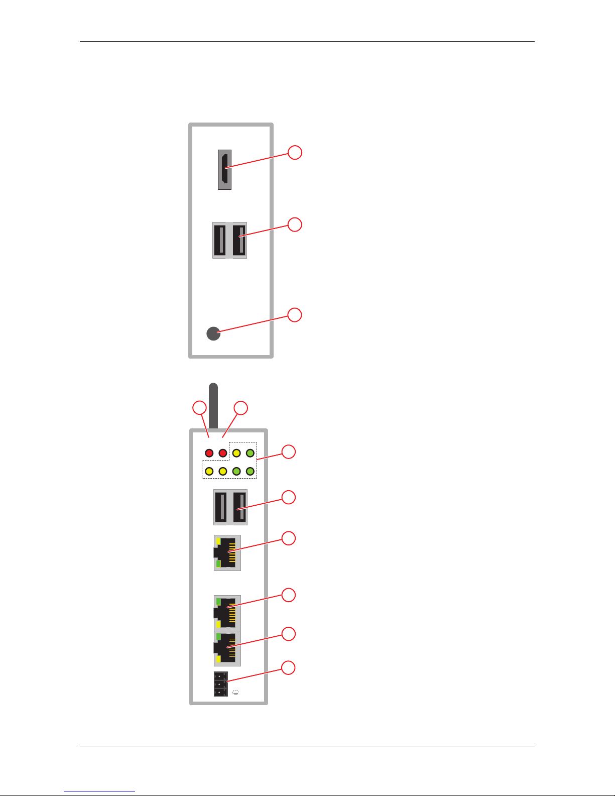
Figure2: NIOT-E-NPI3-51-EN-RE (Top view)
Fieldbus
ERR
NS
6
RUN
MS
APL SYS
LED1 LED2 ACT POW
1
LINK
L/A
LINK
L/A
ACT
Rx/TX
ACT
Rx/TX
IN
CH0
OUT
CH1
--
+
7
8
9
10
11
5
4
Figure3: NIOT-E-NPI3-51-EN-RE (Front view)
netPI | NOIT-E-NPI3-51-EN-RE
DOC170801UM01EN | Revision 1 | English | 2017-09 | Released | Public
© Hilscher 2017
Device drawings 7/64
12
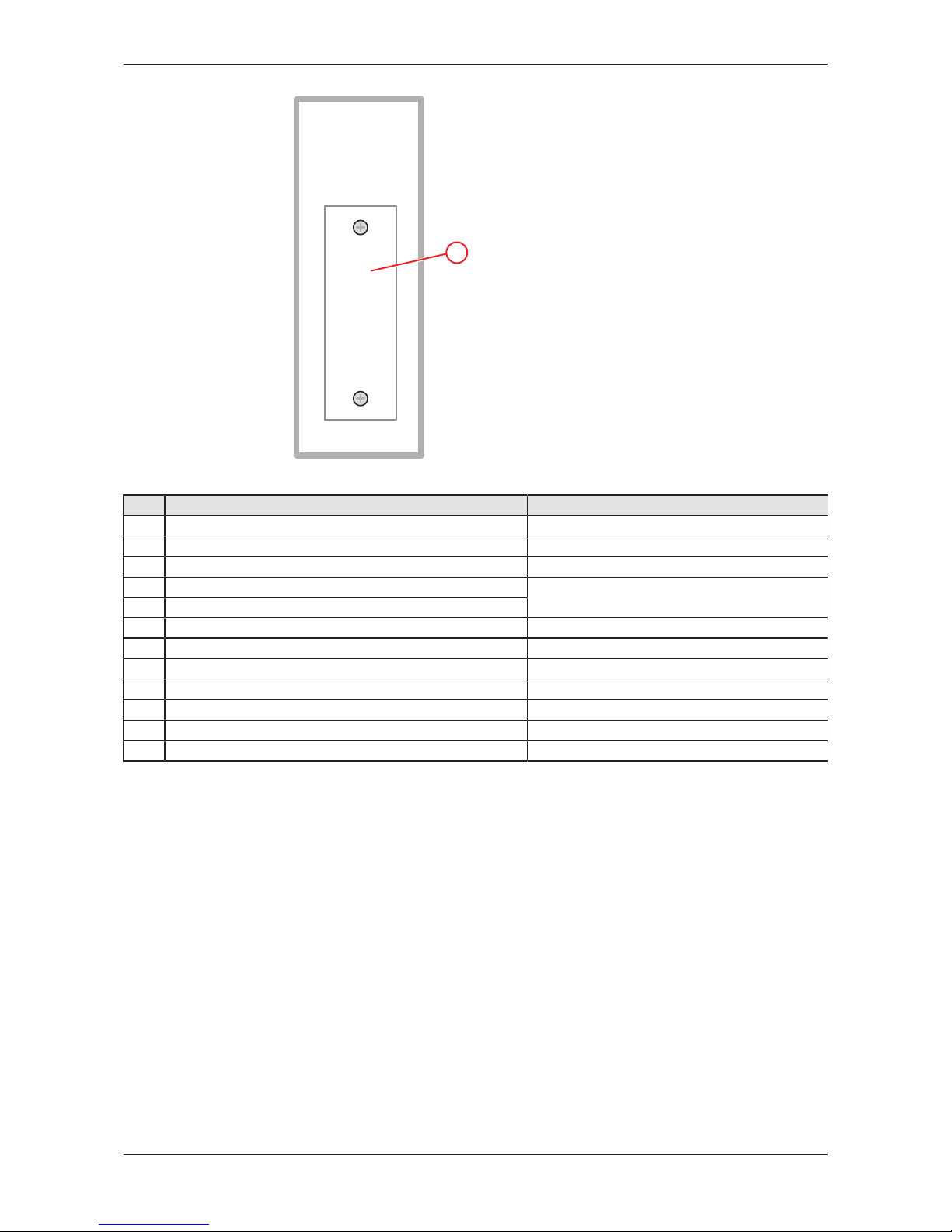
Figure4: NIOT-E-NPI3-51-EN-RE (Bottom view)
Pos. Interface For details see
(1) Connector for digital LCD display (HDMI)
HDMI connector [}page10]
(2) USB connectors (2x USB 2.0 on top of device)
USB connectors [}page9]
(3) Antenna (1 x Wi-Fi)
Wi-Fi [}page10]
(4) ERR/NS LED (communication status)
Names of the LEDs [}page11]
(5) RUN/MS LED (communication status)
(6) Gateway status LEDs (6 x)
Gateway status LEDs [}page12]
(7) USB connectors (2x USB 2.0 on front of device)
USB connectors [}page9]
(8) LAN connector (RJ45 jacket) port 1 / Eth0
LAN connectors [}page9]
(9) Real-Time Ethernet connector (RJ45 jacket) channel 0
Real-Time Ethernet connectors [}page9]
(10) Real-Time Ethernet connector (RJ45 jacket) channel 1
Real-Time Ethernet connectors [}page9]
(11) +24 V DC supply voltage connector (Mini Combicon)
Power supply [}page9]
(12) Slot for expansion module (Cover bolted)
Slot for expansion modules [}page10]
Table3: Positions of the interfaces
netPI | NOIT-E-NPI3-51-EN-RE
DOC170801UM01EN | Revision 1 | English | 2017-09 | Released | Public
© Hilscher 2017
Device drawings 8/64
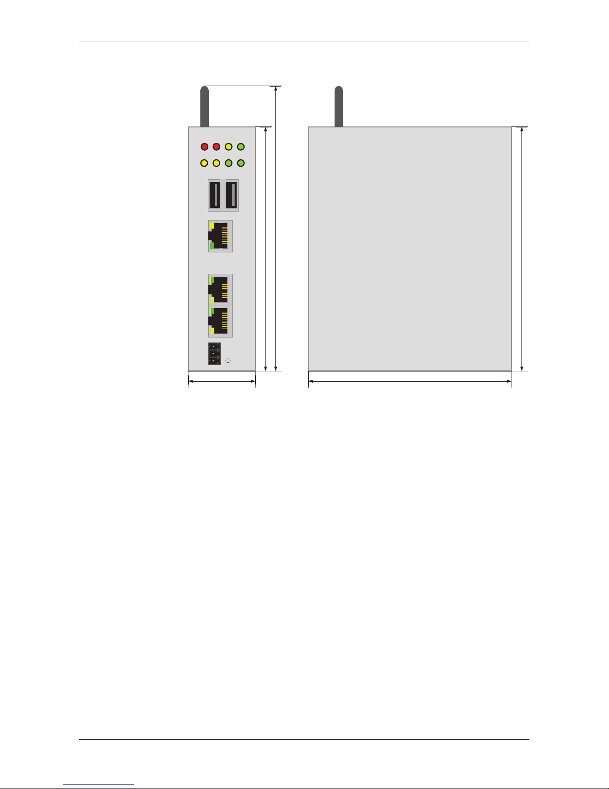
3.2 Dimensions
Fieldbus
ERRNSRUN
MS
APL SYS
LED1 LED2 ACT POW
1
LINK
L/A
LINK
L/A
ACT
Rx/TX
ACT
Rx/TX
IN
CH0
OUT
CH1
--
+
120 mm
140 mm
35 mm
120 mm
100 mm
Figure5: Dimensions
netPI | NOIT-E-NPI3-51-EN-RE
DOC170801UM01EN | Revision 1 | English | 2017-09 | Released | Public
© Hilscher 2017

Connectors and mounting 9/64
4 Connectors and mounting
4.1 Mounting
Mount the Edge Gateway on a DIN rail onto the wall of the cabinet.
4.2 Power supply
DC 24V Pin Signal Description
- GND Ground (Reference potential)
+ +24 V DC +24 V DC
FE Functional earth
Table4: Power supply connector
4.3 LAN connectors
The Edge Gateway has one LAN connector for connecting it to the cloud
network (IT network), position (8) (see section Positions of the
interfaces [}page6]).
The MAC addresses of the LAN interfaces are printed on the device label.
Section Configuring Ethernet communication (LAN) [}page35] describes,
how you can set the IP address parameters of the LAN interfaces.
4.4 Real-Time Ethernet connectors
The Edge Gateway has 2 RJ45-connectors to connect the fieldbus to a
Real-Time Ethernet network (OT network), positions (9) and (10) (see
section Positions of the interfaces [}page6]).
4.5 USB connectors
The Edge Gateway has 4 USB connectors (4 x USB 2.0), positions (2) and
(7) (see section Positions of the interfaces [}page6]).
You can connect for example a USB stick, an external hard drive or a
keyboard and use it together with a Docker image.
netPI | NOIT-E-NPI3-51-EN-RE
DOC170801UM01EN | Revision 1 | English | 2017-09 | Released | Public
© Hilscher 2017

Connectors and mounting 10/64
4.6 Wi-Fi
You can use the Edge Gateway for wireless network communication. The
Edge Gateway supports 2 Wi-Fi operating modes: Access Point and
Client. Operating mode Access Point allows the Edge Gateway to connect
to other Wi-Fi devices in order to configure the Edge Gateway from a
mobile device for example. Operating mode Client allows the Edge
Gateway to be connected to any Wi-Fi Access Point.
Section WiFi describes how you activate the antennas and how to set the
Wi-Fi operating mode.
4.7 HDMI connector
The Edge Gateway has an HDMI-connection for a monitor (position (1))
which is not required for the operation of the Edge Gateway.
The HDMI interface is inactive by default and just outputs boot information
during the boot process of the device. If you want to use it, find an example
docker image with activated HDMI interface and desktop at https://
hub.docker.com/r/hilschernetpi/.
4.8 Slot for expansion modules
To expand the functional range of the device a slot for expansion modules
is provided, e.g. a module for digital I/Os.
netPI | NOIT-E-NPI3-51-EN-RE
DOC170801UM01EN | Revision 1 | English | 2017-09 | Released | Public
© Hilscher 2017
LEDs 11/64
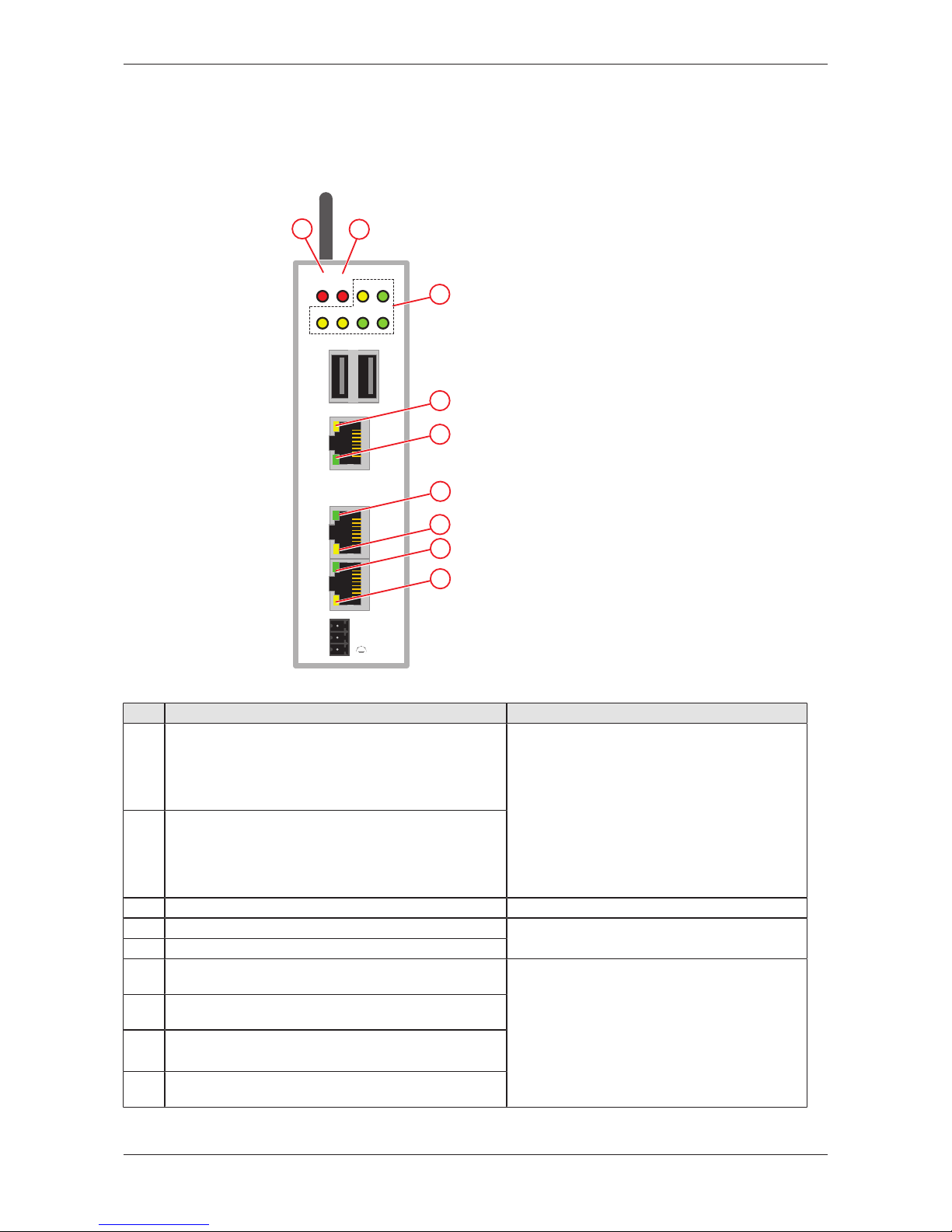
5 LEDs
5.1 Positions of the LEDs on the gateway
Fieldbus
ERR
NS
3
RUN
MS
APL SYS
LED1 LED2 ACT POW
1
LINK
L/A
LINK
L/A
ACT
Rx/TX
ACT
Rx/TX
IN
CH0
OUT
CH1
--
+
4
5
6
8
9
7
1
2
Figure6: LED positions
Pos. LED For details see
(1) ERR/NS communication status Real-Time Ethernet
Name and function depends on used RTE protocol:
PROFINET IO Device: ERR (Bus error)
EtherCAT Slave: ERR (Error)
EtherNet/IP Adapter = NS (Network status)
LEDs of the PROFINET IO Device
interface [}page14]
LEDs der EtherCAT Slave interface [}page15]
LEDs of the EtherNet/IP Adapter
interface [}page16]
(2) RUN/MS communication status Real-Time Ethernet
Name and function depends on used RTE protocol:
PROFINET IO Device: RUN (System error)
EtherCAT Slave: RUN
EtherNet/IP Adapter = MS (Module status)
(3) Gateway status LEDs (6 x)
Gateway status LEDs [}page12]
(4) LINK LAN
LEDs of the LAN interface [}page13]
(5) ACT / RxTx LAN
(6) LINK / L/A Real-Time Ethernet channel 0
Name and function depends on used RTE protocol.
LEDs of the PROFINET IO Device
interface [}page14]
LEDs der EtherCAT Slave interface [}page15]
LEDs of the EtherNet/IP Adapter
interface [}page16]
(7) ACT / Rx/Tx Real-Time Ethernet channel 0
Name and function depends on used RTE protocol.
(8) LINK / L/A Real-Time Ethernet channel 1
Name and function depends on used RTE protocol.
(9) ACT / Rx/Tx Real-Time Ethernet channel 1
Name and function depends on used RTE protocol.
Table5: Names of the LEDs
netPI | NOIT-E-NPI3-51-EN-RE
DOC170801UM01EN | Revision 1 | English | 2017-09 | Released | Public
© Hilscher 2017

LEDs 12/64
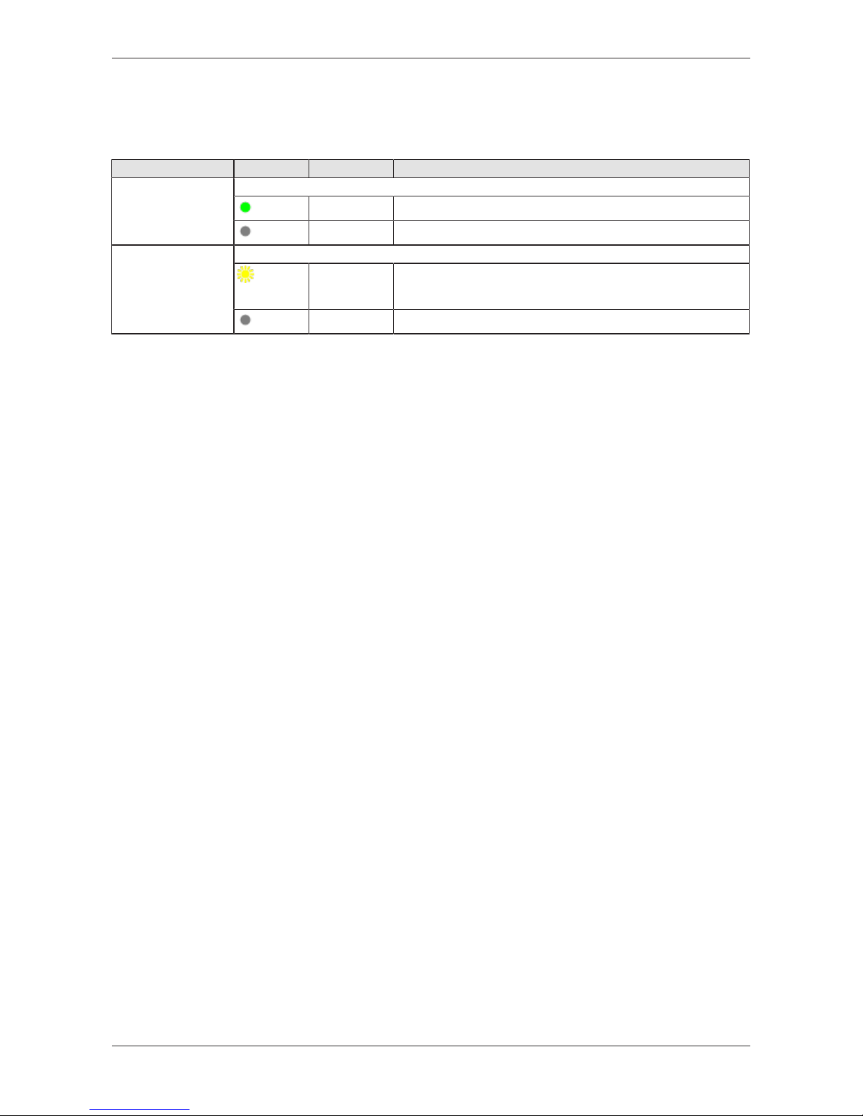
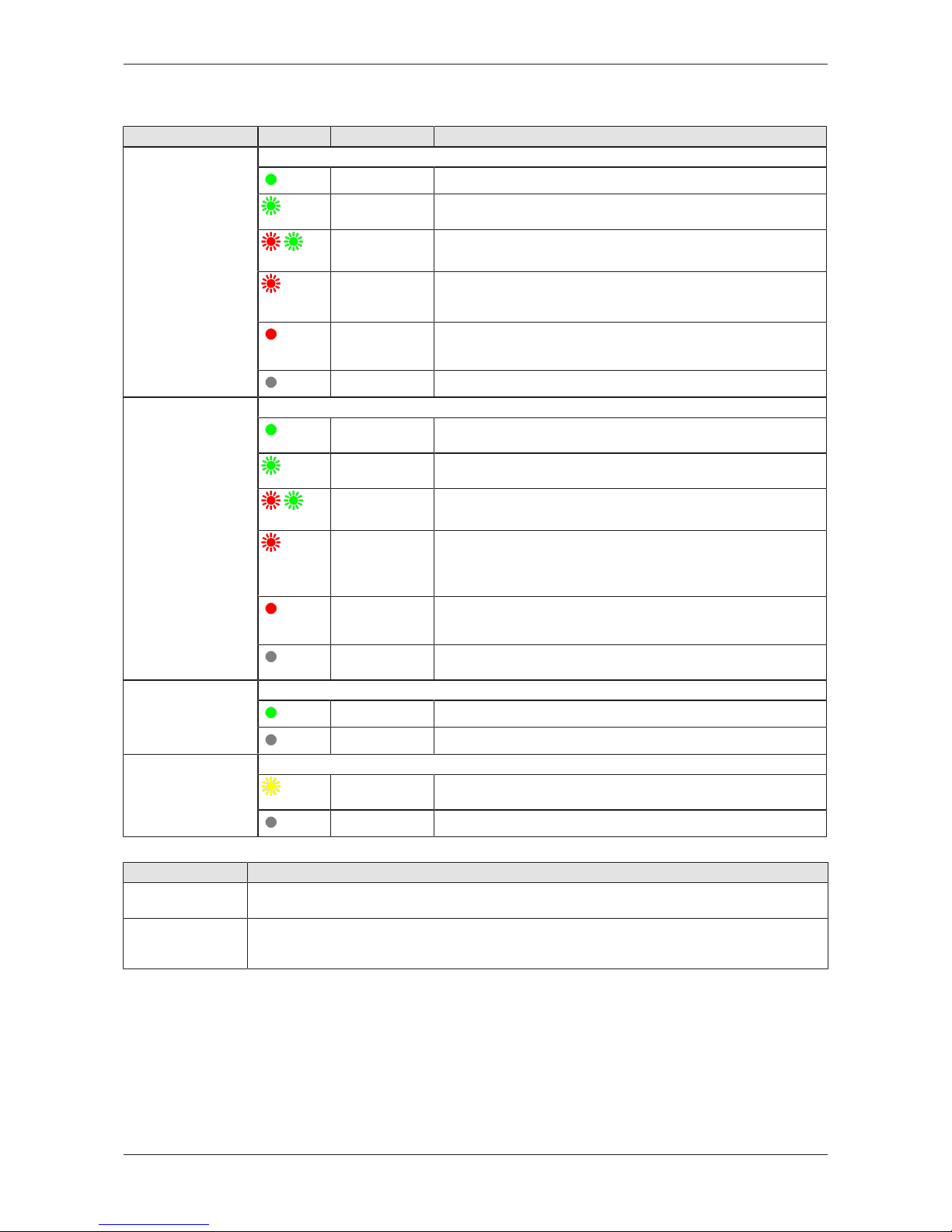
5.2 Gateway status LEDs
LEDs indicating communication status, system status, application status
and voltage supply. The position of the LEDs is indicated by position (3) in
section Positions of the LEDs on the gateway [}page11].
ERR
NSRUN
M
S
APL SYS
LED1 LED2 ACT POW
Figure7: Gateway status LEDs
LED Color Status Meaning
APL
(yellow)
- Application status
Without function.
SYS Duo LED yellow/green System status (Real-Time Ethernet)
(green)
On Operating system Real-Time Ethernet processor is running.
(green/
yellow)
Blinking Real-Time Ethernet processor waits for firmware.
(yellow)/
On Real-Time Ethernet processor (= Romloader) waits for Second
Stage Boot Loader.
(off)
Off Supply voltage missing.
LED1
(yellow)
- GPIO12, programmable
LED2
(yellow)
GPIO13, programmable
ACT
(green)
Blinking Activity
Linux operating system is active.
POW
(green)
On Supply voltage OK
(off)
Off No supply voltage or supply voltage below 4.65 V.
Table6: Description of gateway status LEDs
netPI | NOIT-E-NPI3-51-EN-RE
DOC170801UM01EN | Revision 1 | English | 2017-09 | Released | Public
© Hilscher 2017
LEDs 13/64
5.3 LEDs of the LAN interface
LEDs indicating state of the LAN communication. For the positions of the
LAN LEDs, see section Positions of the LEDs on the gateway [}page11].
LED Color State Meaning
LINK
Position in the device
drawing (3)
LED green
(green)
On 100 MBit MBit network connection
(off)
off 10 MBit or no network connection
RX/TX
Position in the device
drawing (2)
LED yellow
(yellow)
Flickering
(load
dependent)
The device sends/receives frames
(off)
off The device does not send/receive frames.
Table7: LEDs LAN interface
netPI | NOIT-E-NPI3-51-EN-RE
DOC170801UM01EN | Revision 1 | English | 2017-09 | Released | Public
© Hilscher 2017

LEDs 14/64
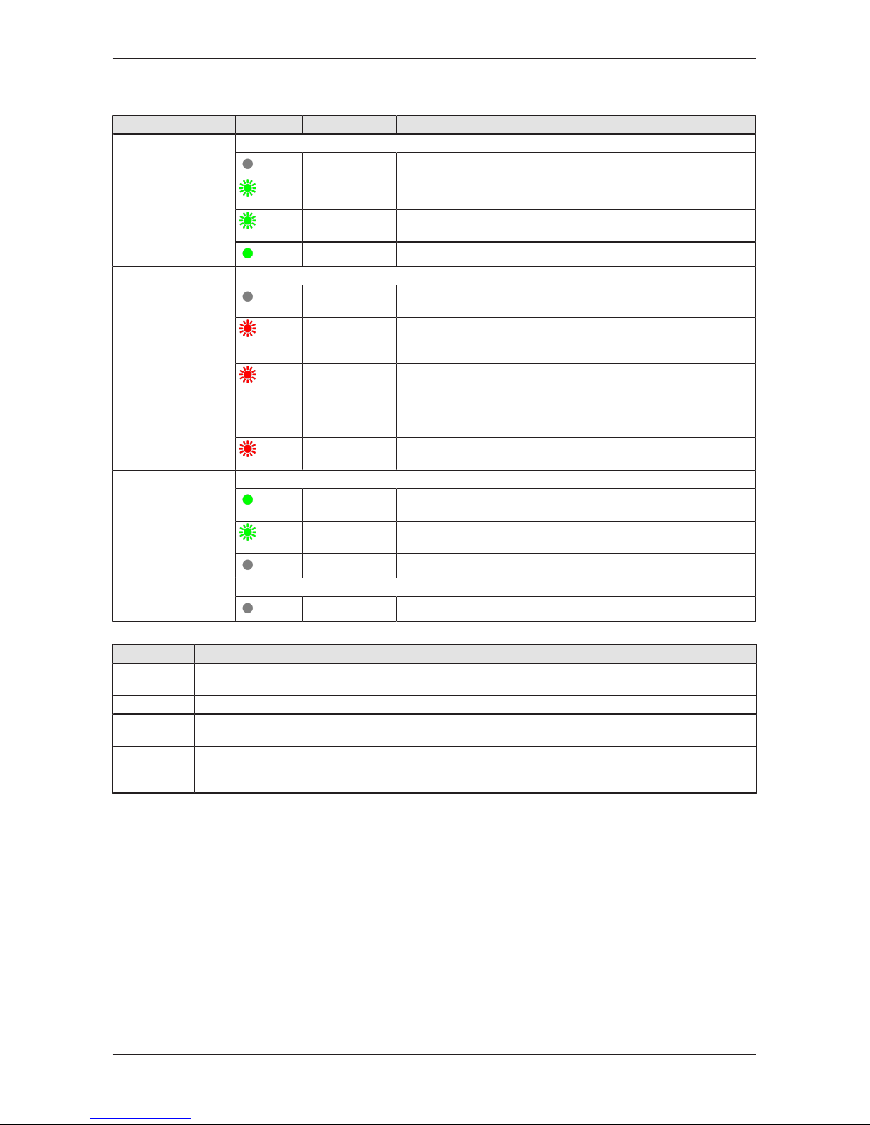
5.4 LEDs of the PROFINET IO Device interface
LED Color State Meaning
RUN (System
Failure)
Position in the device
drawing: (2)
Duo-LED red/green
(off)
Off No error
(red)
Flashing
(1 Hz, 3s)
DCP signal service is initiated via the bus.
(red)
On Watchdog timeout; channel, generic or extended diagnosis
present; system error
ERR (Bus Failure)
Position in the device
drawing: (1)
Duo-LED red/green
(off)
Off No error
(red)
Flashing
(2 Hz)
No data exchange
(red)
On No configuration; or low speed physical link; or no physical link
LINK
CH0 (6) , CH1 (7)
LED green
(green)
On The device is linked to the Ethernet.
(off)
Off The device has no link to the Ethernet.
RX/TX
CH0 (8) , CH1 (9)
LED yellow
(yellow)
Flickering (load
dependent)
The device sends/receives Ethernet frames.
(off)
Off The device does not send/receive Ethernet frames.
Table8: LED states for the PROFINET IO-Device protocol
LED state Definition
Flashing
(1 Hz, 3s)
The indicator turns on and off for 3 seconds with a frequency of 1 Hz:
“on” for 500 ms, followed by “off” for 500 ms.
Flashing
(2 Hz)
The indicator turns on and off with a frequency of 2 Hz:
“on” for 250 ms, followed by “off” for 250 ms.
Flickering (load
dependent)
The indicator turns on and off with a frequency of approximately 10 Hz to indicate high Ethernet
activity: "on" for approximately 50 ms, followed by "off" for 50 ms. The indicator turns on and off in
irregular intervals to indicate low Ethernet activity.
Table9: LED state definitions for the PROFINET IO-Device protocol
netPI | NOIT-E-NPI3-51-EN-RE
DOC170801UM01EN | Revision 1 | English | 2017-09 | Released | Public
© Hilscher 2017
LEDs 15/64
5.5 LEDs der EtherCAT Slave interface
LED Color State Meaning
RUN
Position in the device
drawing: (2)
Duo LED red/green
(off)
Off INIT: The device is in INIT state.
(green)
Blinking
(2.5 Hz)
PRE-OPERATIONAL: The device is in PRE-OPERATIONAL
state.
(green)
Single flash SAFE-OPERATIONAL: The device is in SAFE-OPERATIONAL
state.
(green)
On OPERATIONAL: The device is in the OPERATIONAL state.
ERR
Position in the device
drawing: (1)
Duo LED red/green
(off)
Off No error: The EtherCAT communication of the device is in
working condition.
(red)
Blinking
(2.5 Hz)
Invalid configuration: General Configuration Error
Possible reason: State change commanded by master is
impossible due to register or object settings.
(red)
Single flash Local error: Slave device application has changed the EtherCAT
state autonomously.
Possible reason 1: A host watchdog timeout has occurred.
Possible reason 2: Synchronization Error, device enters SafeOperational automatically.
(red)
Double flash Application watchdog timeout: An application watchdog timeout
has occurred. Possible reason: Sync Manager Watchdog timeout.
L/A IN, L/A OUT
Ch0 (6) , Ch1 (8)
LED green
(green)
On Link: The device is linked to the Ethernet, but does not send/
receive Ethernet frames.
(green)
Flickering (load
dependent)
Activity: The device is linked to the Ethernet and sends/receives
Ethernet frames.
(off)
Off The device has no link to the Ethernet.
Ch0 (7) , Ch1 (9) LED yellow
(off)
Off This LED is not used.
Table10: LED states for the EtherCAT Slave protocol
LED state Definition
Blinking
(2.5 Hz)
The indicator turns on and off with a frequency of 2.5 Hz:
“on” for 200 ms, followed by “off” for 200 ms.
Single flash The indicator shows one short flash (200 ms) followed by a long “off“ phase (1,000 ms).
Double flash The indicator shows a sequence of two short flashes (each 200 ms), separated by a short off phase
(200 ms). The sequence is finished by a long off phase (1,000 ms).
Flickering
(load
dependent)
The indicator turns on and off with a frequency of approximately 10 Hz to indicate high Ethernet activity:
on for approximately 50 ms, followed by off for 50 ms. The indicator turns on and off in irregular intervals
to indicate low Ethernet activity.
Table11: LED state definitions for the EtherCAT Slave protocol
netPI | NOIT-E-NPI3-51-EN-RE
DOC170801UM01EN | Revision 1 | English | 2017-09 | Released | Public
© Hilscher 2017
LEDs 16/64
5.6 LEDs of the EtherNet/IP Adapter interface
LED Color State Meaning
MS
(module status)
Position in the device
drawing: (2)
Duo LED red/green
(green)
On Device operational: The device is operating correctly.
(green)
Flashing
(1 Hz)
Standby: The device has not been configured.
(red/green)
Flashing
(1 Hz)
Self-test:The device is performing its power up testing.
(red)
Flashing
(1 Hz)
Minor fault: The device has detected a recoverable minor fault.
E. g. an incorrect or inconsistent configuration can be considered
as a minor fault.
(red)
On Major fault: The device has detected a non-recoverable major
fault.
(off)
Off No power: The power supply to the device is missing.
NS
(Network status)
Position in the device
drawing: (1)
Duo LED red/green
(green)
On Connected: The device has at least one established connection
(even to the Message Router).
(green)
Flashing
(1 Hz)
No connections:The device has no established connections, but
has obtained an IP address.
(red/green)
Flashing
(1 Hz)
Self-test:The device is performing its power up testing.
(red)
Flashing
(1 Hz)
Connection timeout: One or more of the connections in which
this device is the target have timed out. This status will be finished
only if all timed out connections are reestablished or if the device
is reset.
(red)
On Duplicate IP: The device has detected that its IP address is
already in use.
(off)
(Off) Not powered, no IP address:The device does not have an IP
address (or is powered off).
LINK
CH0 (6) , CH1 (7)
LED green
(green)
On The device is linked to the Ethernet.
(off)
Off The device has no link to the Ethernet.
ACT
CH0 (8) , CH1 (9)
LED yellow
(yellow)
Flickering (load
dependent)
The device sends/receives Ethernet frames.
(off)
Off The device does not send/receive Ethernet frames.
Table12: LED states for the EtherNet/IP Adapter protocol
LED state Definition
Flashing (1 Hz) The indicator turns on and off with a frequency of 1 Hz:
“on” for 500 ms, followed by “off” for 500 ms.
Flickering (load
dependent)
The indicator turns on and off with a frequency of approximately 10 Hz to indicate high Ethernet
activity: on for approximately 50 ms, followed by off for 50 ms. The indicator turns on and off in
irregular intervals to indicate low Ethernet activity
Table13: LED state definitions for the EtherNet/IP Adapter protocol
netPI | NOIT-E-NPI3-51-EN-RE
DOC170801UM01EN | Revision 1 | English | 2017-09 | Released | Public
© Hilscher 2017
Commissioning the Edge Gateway 17/64
6 Commissioning the Edge Gateway
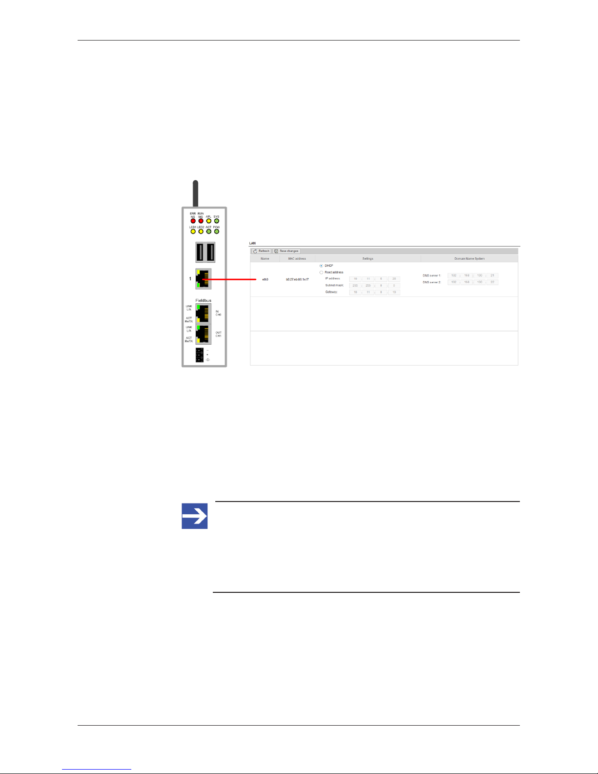
6.1 Establishing the IP address communication
An IP address is required to address the Edge Gateway in the LAN
network.
The following figure shows the factory setting of the LAN interfaces and the
assignment of the connections.
Figure8: Default settings of the Ethernet network connectors
Network connection - DHCP server available
If a DHCP server is available in the network:
Ø Use an Ethernet cable to connect the LAN connection port 1 (eth0)
(see (7) in Positions of the interfaces [}page6]) with a network in which
a DHCP server is available.
ð The Edge Gateway obtains an IP address from the DHCP server.
Access to the Edge Gateway is possible now.
Note:
The Edge Gateway sends a request to a DHCP server once after
switching on the device or after each connection of the Ethernet
cable, i.e. when the Edge Gateway detects a link signal. If you want
to activate a request of the Edge Gateway to the DHCP server
manually, pull off the Ethernet cable from the Edge Gateway and
reconnect it to the Edge Gateway.
Read section Using the web browser to establish a connection with the
Edge Gateway [}page18] to find out how to access the Edge Gateway.
netPI | NOIT-E-NPI3-51-EN-RE
DOC170801UM01EN | Revision 1 | English | 2017-09 | Released | Public
© Hilscher 2017

Commissioning the Edge Gateway 18/64
6.2 Using the web browser to establish a connection with the
Edge Gateway
You have three possibilities to access the Edge Gateway:
1. by means of the host name (see section Using the host
name [}page18])
2. by access via the Windows network (see section Access to the Edge
Gateway in the Windows network environment [}page19]),
3. by using the IP address (see section Using the IP address).
6.2.1 Using the host name
The Edge Gateway has a host name you can use to access the device.
Where do you find the host name on the device?
The device is delivered (factory setting) with a label printed at its bottom. In
the figure below the host name has a red frame.
Establishing a connection with the host name
Ø Enter the following address in the address line of your browser:
https://<hostname>
Example: For the device with the host name NT0002A233E559 enter
https://NT0002A233E559
ð The Edge Gateway Manager opens.
You can now use the Edge Gateway manager to configure the device. For
this purpose, read section Edge Gateway manager web page [}page21].
netPI | NOIT-E-NPI3-51-EN-RE
DOC170801UM01EN | Revision 1 | English | 2017-09 | Released | Public
© Hilscher 2017

Commissioning the Edge Gateway 19/64
6.2.2 Access to the Edge Gateway in the Windows network environment
To be located easily in the network, the Edge Gateway uses the UPnP
technology (Universal Plug and Play). This technology will display the Edge
Gateway in the Windows network environment.
Ø To display all devices in the network, click on Network in the Windows
Explorer.
Ê You will find the Edge Gateway under Other Devices:
Figure9: netIOT Edge Gateway in the Windows network
Ø Open the context menu of this entry and select Properties.
Ê The menu provides information on the Edge Gateway, e.g. serial
number, MAC address, host name or die IP address.
Ø Click on the link under Device web page.
ð The Edge Gateway manager opens.
Ø To open the Edge Gateway manager, you can also double-click on the
device icon.
ð The Edge Gateway manager opens.
You can now use the Edge Gateway manager to configure the device. For
this purpose, read section Edge Gateway manager web page [}page21].
netPI | NOIT-E-NPI3-51-EN-RE
DOC170801UM01EN | Revision 1 | English | 2017-09 | Released | Public
© Hilscher 2017

Edge Gateway manager 20/64
7 Edge Gateway manager
7.1 Calling the Edge Gateway Manager
The Edge Gateway manager is a web page with tiles that allow rapid
access to the applications integrated in the device or to external web
pages.
The Edge Gateway uses the secured HTTPS protocol to access web pages
stored in the Edge Gateway.
Ø To open the Edge Gateway manager, enter the following information in
the address line of your browser:
https://<Host name of the Edge Gateway>
or
https://<IP address of the Edge Gateway>
ð Your browser displays the Edge Gateway manager.
Figure10: Edge Gateway Manager
Note:
Remember that the secured HTTPS protocol is used here, not the
widely spread HTTP protocol.
netPI | NOIT-E-NPI3-51-EN-RE
DOC170801UM01EN | Revision 1 | English | 2017-09 | Released | Public
© Hilscher 2017
 Loading...