

Page 1
User manual
netIOT Edge Gateway
NIOT-E-TIJCX-GB-RE (On-Premise)
V1.2.0.0
Hilscher Gesellschaft für Systemautomation mbH
www.hilscher.com
DOC160402UM07EN | Revision 7 | English | 2019-07 | Released | Public
Page 2

Table of contents 2/292
Table of contents
1 Introduction .............................................................................................................................. 7
1.1 About the user manual .....................................................................................................7
1.2 List of revisions ................................................................................................................7
2 Brief description ...................................................................................................................... 8
3 Device drawings..................................................................................................................... 10
3.1 Positions of the interfaces ..............................................................................................10
3.2 Dimensions ....................................................................................................................12
4 Connectors and mounting .................................................................................................... 13
4.1 Mounting ........................................................................................................................13
4.2 LED sticker.....................................................................................................................13
4.3 Power supply..................................................................................................................14
4.4 LAN connectors..............................................................................................................14
4.5 Real-Time Ethernet connectors .....................................................................................14
4.6 USB connectors .............................................................................................................14
4.7 Serial interfaces COM1 and COM2................................................................................15
4.7.1 RS-232............................................................................................................15
4.7.2 RS-422............................................................................................................16
4.7.3 RS-485............................................................................................................16
4.8 Wi-Fi...............................................................................................................................17
4.9 Preparing gateway for cellular communication ..............................................................17
4.10 Monitor connectors.........................................................................................................20
5 LEDs........................................................................................................................................21
5.1 Positions of the LEDs on the gateway ...........................................................................21
5.2 Gateway status LEDs.....................................................................................................22
5.3 LEDs of the LAN interface..............................................................................................23
5.4 LEDs of the PROFINET IO Device interface..................................................................24
5.5 LEDs of the EtherNet/IP Adapter interface ....................................................................25
6 Commissioning the Edge Gateway ...................................................................................... 27
6.1 Establishing the IP address communication ..................................................................27
6.2 Using the web browser to establish a connection with the Edge Gateway ....................29
6.2.1 Using the host name ....................................................................................... 29
6.2.2 Access to the Edge Gateway in the Windows network environment .............. 30
6.2.3 Using the IP address....................................................................................... 31
7 Edge Gateway Manager......................................................................................................... 32
7.1 Calling the Edge Gateway Manager ..............................................................................32
7.2 Edge Gateway Manager web page................................................................................33
8 Control Panel.......................................................................................................................... 35
8.1 Opening the control panel ..............................................................................................35
8.1.1 First login ........................................................................................................ 36
8.1.2 Secure connection .......................................................................................... 37
Edge Gateway | NIOT-E-TIJCX-GB-RE (On-Premise)
DOC160402UM07EN | Revision 7 | English | 2019-07 | Released | Public
© Hilscher 2016 – 2019
Page 3

Table of contents 3/292
8.2 Overview and main menu ..............................................................................................41
8.3 System information and system time ............................................................................. 43
8.3.1 Displaying system information ........................................................................ 43
8.3.2 License Manager ............................................................................................ 44
8.3.3 Displaying the system log files........................................................................ 47
8.3.4 Setting the system time................................................................................... 51
8.3.5 Configure ports for HTTP/HTTPS communication.......................................... 53
8.3.6 Backup and restore......................................................................................... 55
8.3.7 Rebooting the system ..................................................................................... 62
8.3.8 System shutdown............................................................................................ 63
8.4 Packet management ......................................................................................................63
8.4.1 Managing packets........................................................................................... 63
8.5 Network ..........................................................................................................................64
8.5.1 Configuring Ethernet communication (LAN) ................................................... 64
8.5.2 Configuring wireless communication (Wi-Fi)................................................... 67
8.5.3 Field ................................................................................................................ 73
8.5.4 Configuring cellular communication ................................................................ 74
8.5.5 Configuring IP Routes..................................................................................... 78
8.5.6 Configuring Firewall ........................................................................................ 82
8.5.7 Hostname........................................................................................................ 84
8.6 Services .........................................................................................................................85
8.6.1 Starting, stopping and configuring services .................................................... 85
8.7 User management..........................................................................................................89
8.7.1 Managing user roles ....................................................................................... 89
8.7.2 Managing user accounts................................................................................. 91
8.8 Security ..........................................................................................................................92
8.8.1 Public Key Infrastructure................................................................................. 92
8.9 Help................................................................................................................................95
8.10 Session ..........................................................................................................................95
8.10.1 User profile...................................................................................................... 95
8.10.2 Logout ............................................................................................................. 96
9 Node-RED - The wiring editor ............................................................................................... 97
9.1 Modelling IoT flows with nodes ......................................................................................98
9.2 Opening Node-RED .......................................................................................................99
9.3 Graphical user interface ...............................................................................................101
9.4 Working with Node-RED .............................................................................................. 103
9.4.1 Using Git hub repository to store flows (projects) ......................................... 105
9.4.2 Menu Deploy................................................................................................. 106
9.4.3 Dashboard .................................................................................................... 108
9.5 List of nodes.................................................................................................................119
9.6 MQTT input node .........................................................................................................122
9.7 MQTT output node .......................................................................................................126
10 Examples for Node-RED...................................................................................................... 128
10.1 Example 1: Inject and debug node...............................................................................128
10.2 Example 2: MQTT input node ......................................................................................130
10.3 Example 3: MQTT output node ....................................................................................134
10.4 Example 4: Fieldbus input node...................................................................................138
Edge Gateway | NIOT-E-TIJCX-GB-RE (On-Premise)
DOC160402UM07EN | Revision 7 | English | 2019-07 | Released | Public
© Hilscher 2016 – 2019
Page 4

Table of contents 4/292
10.5 Example 5: Fieldbus output node.................................................................................146
11 Configuring and using the fieldbus node.......................................................................... 154
11.1 Overview ......................................................................................................................154
11.2 Configuring the fieldbus and defining the signals.........................................................156
11.2.1 Creating a new fieldbus configuration........................................................... 156
11.2.2 Changing the existing fieldbus configuration ................................................ 161
12 Configuring PROFINET and defining signals.................................................................... 166
12.1 User interface...............................................................................................................166
12.2 Menu commands..........................................................................................................166
12.2.1 Project - Save ............................................................................................... 167
12.2.2 GSDML Download ........................................................................................ 167
12.2.3 Printing the configuration .............................................................................. 167
12.2.4 Help - Contents ............................................................................................. 168
12.2.5 Help - Information ......................................................................................... 168
12.3 Configuration tree.........................................................................................................169
12.3.1 PROFINET configuration .............................................................................. 169
12.3.2 IO and signal configuration ........................................................................... 170
12.3.3 Signal definitions overview............................................................................ 179
12.3.4 Download of the GSDML file......................................................................... 180
12.3.5 Help............................................................................................................... 180
13 Configuring EtherNet/IP and defining signals .................................................................. 181
13.1 User interface...............................................................................................................181
13.2 Menu commands..........................................................................................................181
13.2.1 Project - Save ............................................................................................... 182
13.2.2 EDS Download.............................................................................................. 182
13.2.3 Printing the configuration .............................................................................. 183
13.2.4 Help - Contents ............................................................................................. 183
13.2.5 Help - Information ......................................................................................... 183
13.3 Configuration tree.........................................................................................................184
13.3.1 EtherNet/IP configuration.............................................................................. 184
13.3.2 IO and signal configuration ........................................................................... 185
13.3.3 Signal definitions overview............................................................................ 194
13.3.4 Download of the EDS file .............................................................................. 195
13.3.5 Help............................................................................................................... 195
14 Edge Server .......................................................................................................................... 196
14.1 Function principle .........................................................................................................196
14.1.1 Communication with IT-network and mobile devices.................................... 196
14.1.2 Communication with the OT-network............................................................ 198
14.1.3 Access rights to the REST API ..................................................................... 198
14.1.4 Functions of the Edge Server ....................................................................... 199
14.1.5 Internal structure of the Edge Server ............................................................ 200
14.2 Edge Server Control Center.........................................................................................201
14.2.1 Starting the Edge Server Control Center ...................................................... 201
14.2.2 Functions ...................................................................................................... 201
14.2.3 Service list..................................................................................................... 202
14.3 Configuration of the Edge Server.................................................................................204
14.3.1 The configuration of IP address area............................................................ 204
14.3.2 Selecting the protocols to scan for field devices ........................................... 207
Edge Gateway | NIOT-E-TIJCX-GB-RE (On-Premise)
DOC160402UM07EN | Revision 7 | English | 2019-07 | Released | Public
© Hilscher 2016 – 2019
Page 5

Table of contents 5/292
15 Isolated application execution with Docker ...................................................................... 208
15.1 Docker, Image, Container and Repository ...................................................................208
15.2 Prerequisites for working with Docker..........................................................................210
15.3 Working with Docker via the web GUI..........................................................................211
15.3.1 The portainer.io interface .............................................................................. 211
15.3.2 Commissioning ............................................................................................. 211
15.3.3 Starting the portainer.io interface for working with the containers ................ 213
15.3.4 Functions for working with containers........................................................... 216
15.3.5 Example: Execute web server NGINX as a container .................................. 217
15.3.6 User management ........................................................................................ 218
15.3.7 Registry management................................................................................... 222
15.3.8 Stack management ....................................................................................... 231
16 Public Key Infrastructure .................................................................................................... 237
16.1 Asymmetric encryption.................................................................................................237
16.2 Certificates and keys....................................................................................................239
16.2.1 Structure of a certificate according to X.509 ................................................. 239
16.2.2 Hierarchy of trust........................................................................................... 240
16.2.3 File formats for certificate and key files......................................................... 241
16.3 Use cases ....................................................................................................................242
16.3.1 Use case 1: Verification of the authenticity of the communication partner
(Server) ......................................................................................................... 242
16.3.2 Use case 2: Server certificates for Edge Gateway services ......................... 243
16.3.3 Use case 3: Client certificates for specific servers........................................ 245
16.4 Verification of the authenticity of the communication partner using trustworthy
certificates ....................................................................................................................247
16.4.1 Display the list of trustworthy root certificates stored within the Edge Gateway ..
247
16.4.2 Upload a trustworthy certificate into the Edge Gateway ............................... 248
16.4.3 Download of certificates from the Edge Gateway into a file.......................... 249
16.4.4 Removing certificates no longer considered as trustworthy.......................... 249
16.5 Working with server certificates for inbound connections ............................................ 250
16.5.1 Uploading a a pair of certificate file and key file for HTTPS und OPC UA Server
250
16.5.2 Working with certificates for HTTPS and OPC UA Server............................ 253
16.5.3 Working with key files for HTTPS and OPC UA Server ................................ 255
16.6 Working with client authentication certificates for outbound connections .................... 256
16.6.1 Uploading a pair of certificate and corresponding key file for client
authentication................................................................................................ 257
16.6.2 Working with certificates for client authentication ......................................... 260
16.6.3 Working with key files for client authentication ............................................. 263
17 Firmware recovery ............................................................................................................... 265
17.1 Overview ......................................................................................................................265
17.2 Prerequisites ................................................................................................................265
17.3 Step-by-step instructions..............................................................................................266
18 Technical data ...................................................................................................................... 274
18.1 Technical data NIOT-E-TIJCX-GB-RE.........................................................................274
18.2 Technical data PROFINET IO Device..........................................................................276
18.3 Technical data EtherNet/IP Adapter.............................................................................277
Edge Gateway | NIOT-E-TIJCX-GB-RE (On-Premise)
DOC160402UM07EN | Revision 7 | English | 2019-07 | Released | Public
© Hilscher 2016 – 2019
Page 6

Table of contents 6/292
19 Decommissioning, dismounting and disposal ................................................................. 278
19.1 Putting the device out of operation...............................................................................278
19.2 Removal of battery .......................................................................................................278
19.3 Disposal of waste electronic equipment.......................................................................279
20 Appendix............................................................................................................................... 280
20.1 Legal notes...................................................................................................................280
List of figures ....................................................................................................................... 284
List of tables......................................................................................................................... 289
Contacts................................................................................................................................ 292
Edge Gateway | NIOT-E-TIJCX-GB-RE (On-Premise)
DOC160402UM07EN | Revision 7 | English | 2019-07 | Released | Public
© Hilscher 2016 – 2019
Page 7

Introduction 7/292
1 Introduction
1.1 About the user manual
This user manual describes the installation, configuration and functionality
of the device NIOT-E-TIJCX-GB-RE.
1.2 List of revisions
Revision Date Author Revision
5 13.08.2018-
08-13
6 2018-10-08 RGö, HHe
7 2019-07-03 HHe, RGö,
RGö, HHe
MKe
Table1: List of revisions
Section Displaying the system log files [}page47] added.
Section Security [}page92] added.
Section Public Key Infrastructure [}page237] added.
Section Configuring wireless communication (Wi-Fi) [}page67] updated.
Section Public Key Infrastructure [}page237] updated.
Section Configure ports for HTTP/HTTPS communication [}page53] added.
Section Managing packets [}page63] updated.
Section Configuring Ethernet communication (LAN) [}page64] updated and
DHCP server added.
Section Configuring wireless communication (Wi-Fi) [}page67] updated.
Section Configuring cellular communication [}page74] added.
Section Configuring IP Routes [}page78] added.
Section Configuring Firewall [}page82] added.
Section Graphical user interface [}page101] updated.
Sections MQTT input node [}page122] and MQTT output node [}page126]
updated.
Sections Example 4: Fieldbus input node [}page138] and Example 5: Fieldbus
output node [}page146] updated.
Section Configuring the fieldbus and defining the signals [}page156]updated.
Chapter Isolated application execution with Docker [}page208] updated.
Edge Gateway | NIOT-E-TIJCX-GB-RE (On-Premise)
DOC160402UM07EN | Revision 7 | English | 2019-07 | Released | Public
© Hilscher 2016 – 2019
Page 8
Brief description 8/292
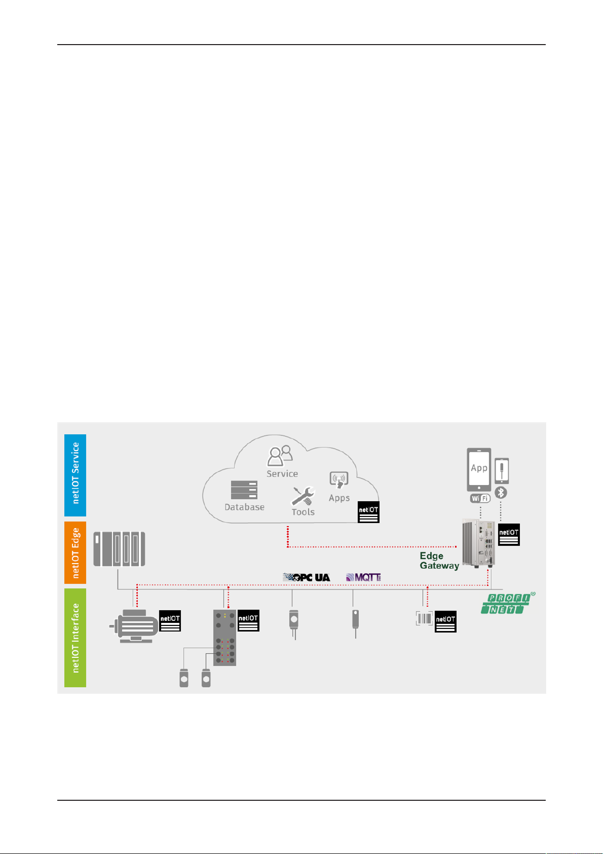
2 Brief description
Hilscher's netIOT Edge Gateway NIOT-E-TIJCX-GB-RE securely connects
Real-Time Ethernet automation networks with a „Cloud“ or any IoT-directed
application.
As a field device, it is performing a cyclic I/O data exchange with the PLC
and communicates with further IoT-capable field devices within the
automation network.
These key field data exchanged in real-time form the basis for intelligent
higher-level IoT applications for cyber-physical processes and M2M
solutions.
The gateway is designed for continuous operation in environments with
permanent intranet or Internet connection. Security mechanisms such as
the physical separation of automation and IT network, a secure operating
system, the execution of signed firmware and packets, as well as
encryption techniques of the latest standards secure the data integrity and
offer protection against data theft.
The gateway base function forms the web-based Thing Wiring editor NodeRED, which serves to model the flows in the devices. Data apps and data
profiles are created within minutes with predefined function blocks of the
editor. OPC UA and MQTT functions address objects in IoT-capable field
devices or in the cloud via standardized IoT protocols.
The Hilscher netIOT Service offers additional software packets to extend
the Edge Gateway base functions by further applications or accesses to
specific clouds.
Figure1: Edge Gateway communication structure
Edge Gateway | NIOT-E-TIJCX-GB-RE (On-Premise)
DOC160402UM07EN | Revision 7 | English | 2019-07 | Released | Public
© Hilscher 2016 – 2019
Page 9

Brief description 9/292
The open source software „Docker“ by Docker, Inc. allows the user to
execute own applications on the secured Linux operating system of the
Edge Gateways while all protection mechanisms are fully preserved. The
applications are executed in protected, isolated runtime environments. To
accomplish this, Docker uses special techniques from virtualization of
operating systems.
Edge Gateway | NIOT-E-TIJCX-GB-RE (On-Premise)
DOC160402UM07EN | Revision 7 | English | 2019-07 | Released | Public
© Hilscher 2016 – 2019
Page 10
Device drawings 10/292
3 Device drawings
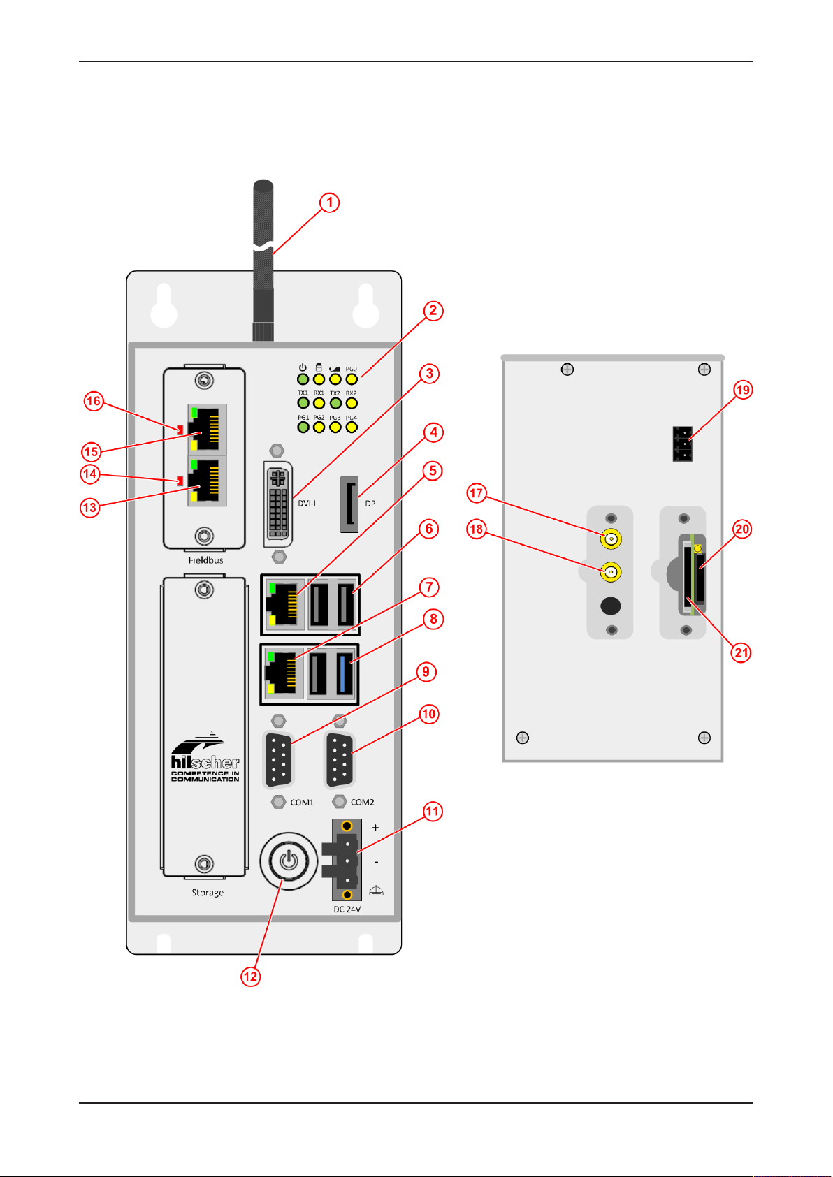
3.1 Positions of the interfaces
Figure2: Positions of the interfaces of NIOT-E-TIJCX-GB-RE front and top view
Edge Gateway | NIOT-E-TIJCX-GB-RE (On-Premise)
DOC160402UM07EN | Revision 7 | English | 2019-07 | Released | Public
© Hilscher 2016 – 2019
Page 11

Device drawings 11/292
Pos. Interface For details see
(1) Antennas (Wi-Fi antennas are included in the delivery;
cellular radio antennas are not included)
(2) Gateway state LEDs (12 x)
(3) Connector for digital LCD display (DVI-I)
(4) Connector for display (DisplayPort)
(5) LAN connector (RJ45 jacket) port 2 / Eth1
(6) USB connectors (3x USB 2.0)
(7) LAN connector (RJ45 jacket) port 1 / Eth0
(8) USB connector (1x USB 3.0)
(9) Serial interface connector COM1 (RS-232/422/485, can be
configured)
(10) Serial interface connector COM2 (RS-232/422/485, can be
configured)
(11) +24 V DC supply voltage connector (Combicon)
(12) Power button On/Off -
(13) Real-Time Ethernet connector (RJ45 jacket) channel 1
(14) LED communication state of Real-Time Ethernet.
LED communication state of Real-Time Ethernet connection.
Name und function depends on used RTE protocol:
PROFINET IO Device = BF (Bus failure)
EtherNet/IP Adapter = NS (network status)
(15) Real-Time Ethernet connector (RJ45 jacket) channel 0
(16) LED communication state of Real-Time Ethernet
LED communication state of Real-Time Ethernet connection.
Name und function depends on used RTE protocol:
PROFINET IO Device = SF (System failure)
EtherNet/IP Adapter = MS (module status)
(17) SMA connector for WiFi or cellular radio antenna
(18) SMA connector for WiFi or cellular radio antenna
(19) Remote push button connector (without function) -
(20) SIM card holder (under removable cover) Preparing gateway for cellular
(21) SD card holder (under removable cover, without function) -
Table2: Positions of the interfaces of NIOT-E-TIJCX-GB-RE
Wi-Fi [}page17]
Preparing gateway for cellular
communication [}page17]
Gateway status LEDs [}page22]
Monitor connectors [}page20]
LAN connectors [}page14]
USB connectors [}page14]
LAN connectors [}page14]
USB connectors [}page14]
Serial interfaces COM1 and COM2 [}page15]
Power supply [}page14]
Real-Time Ethernet connectors [}page14]
LEDs of the PROFINET IO Device
interface [}page24]
LEDs of the EtherNet/IP Adapter
interface [}page25]
Real-Time Ethernet connectors [}page14]
LEDs of the PROFINET IO Device
interface [}page24]
LEDs of the EtherNet/IP Adapter
interface [}page25]
Wi-Fi [}page17]
Preparing gateway for cellular
communication [}page17]
communication [}page17]
Edge Gateway | NIOT-E-TIJCX-GB-RE (On-Premise)
DOC160402UM07EN | Revision 7 | English | 2019-07 | Released | Public
© Hilscher 2016 – 2019
Page 12
Device drawings 12/292
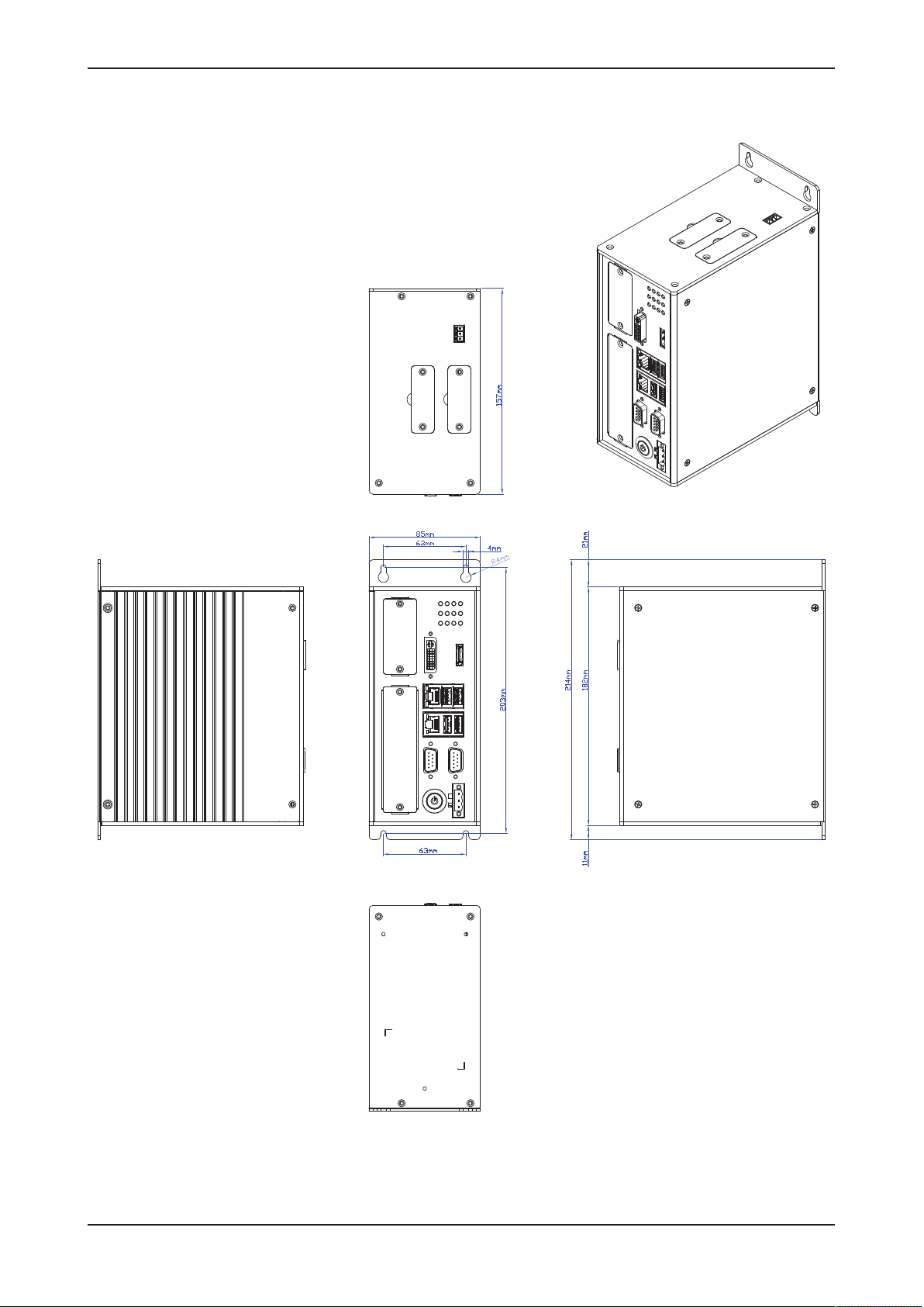
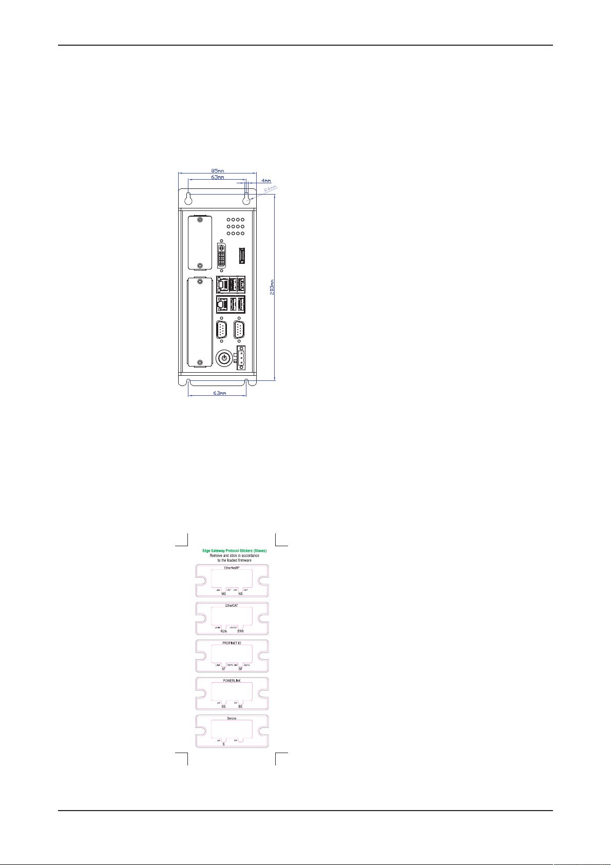
3.2 Dimensions
Figure3: Dimensions
Edge Gateway | NIOT-E-TIJCX-GB-RE (On-Premise)
DOC160402UM07EN | Revision 7 | English | 2019-07 | Released | Public
© Hilscher 2016 – 2019
Page 13
Connectors and mounting 13/292
4 Connectors and mounting
4.1 Mounting
Mount the Edge Gateway with 4 screws into the control cabinet. The
following figure shows the distance of the mounting holes.
Figure4: Drilling template
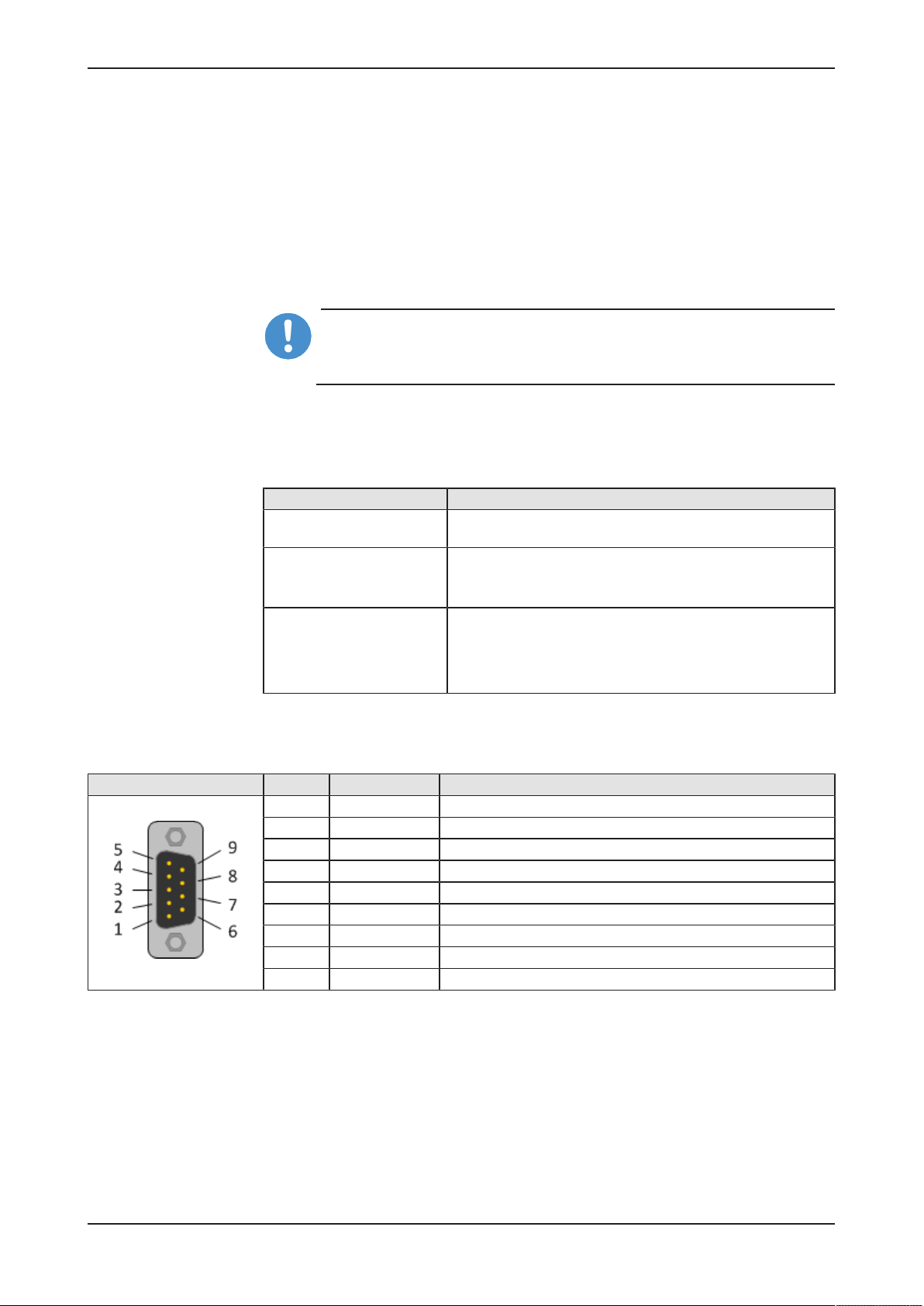
4.2 LED sticker
Each fieldbus system uses its own names for the LED displays. Therefore,
an LED sticker with the names of the respective fieldbus system is included
within the delivery of the Edge Gateway. Stick the sticker of the fieldbus
system to be used to the I/O shield of the fieldbus interface of the Edge
Gateway.
Figure5: LED sticker
Edge Gateway | NIOT-E-TIJCX-GB-RE (On-Premise)
DOC160402UM07EN | Revision 7 | English | 2019-07 | Released | Public
© Hilscher 2016 – 2019
Page 14

Connectors and mounting 14/292
4.3 Power supply
DC 24V Pin Signal Description
+ +24 V DC +24 V DC
- GND Ground (Reference potential)
FE Functional earth
Table3: Power supply connector
4.4 LAN connectors
The Edge Gateway has two LAN connectors for connecting it to the cloud
network, positions (7) and (5) (see section Positions of the
interfaces [}page10]).
The MAC addresses of the LAN interfaces are printed on the device label.
Section Configuring Ethernet communication (LAN) [}page64] describes,
how you can set the IP address parameters of the LAN interfaces.
4.5 Real-Time Ethernet connectors
The Edge Gateway has 2 RJ45-connectors to connect the fieldbus to a
Real-Time Ethernet network (OT network), positions (15) and (13) (see
section Positions of the interfaces [}page10]).
For data exchange at the fieldbus, use the fieldbus input and output in node
Node-RED. Sections Example 4: Fieldbus input node [}page138] and
Example 5: Fieldbus output node [}page146] describe how to access the
cyclic I/O data of the fieldbus in Node-RED.
4.6 USB connectors
The Edge Gateway has 4 USB connectors (1), positions (6) and (8) (see
section Positions of the interfaces [}page10]).
You do not need the USB connectors for operation of the Edge Gateway.
You need the USB connector if you connect a keyboard in order to change
settings in the BIOS or if you do a firmware recovery with a USB stick.
Edge Gateway | NIOT-E-TIJCX-GB-RE (On-Premise)
DOC160402UM07EN | Revision 7 | English | 2019-07 | Released | Public
© Hilscher 2016 – 2019
Page 15
Connectors and mounting 15/292
4.7 Serial interfaces COM1 and COM2
The Edge Gateway has 2 configurable serial interfaces COM1 (position (9))
and COM2 (position (10)). You can use each serial interface as RS-232,
RS-422 or RS-485 interface.
Prerequisites
You have to set the interface type in the BIOS. For this, you need a
keyboard with USB connector and a monitor with DVI-I or DP connector.
Important:
NUse only 1:1 DVI or DP connectors. Adapters like DVI-I to VGA or
DP to VGA are not supported by the gateway.
BIOS settings
In the BIOS, select Advanced > IT8786 Super IO Configuration > Serial
Port 1 Configuration for COM1 or Serial Port 2 Configuration for COM2.
Serial Port Configuration Parameter
Serial Port Enabled
Disabled
Device Settings Display only
Serial Port 1 (COM1): IO=248h; IRQ=5
Serial Port 2 (COM2): IO=2F8h; IRQ=3
Onboard Serial Port Mode RS232
RS422
RS485 (do not use this setting)
RS485 Auto (use this setting for RS-485 only, because RTS
control is active)
Table4: Parameters of the serial interface
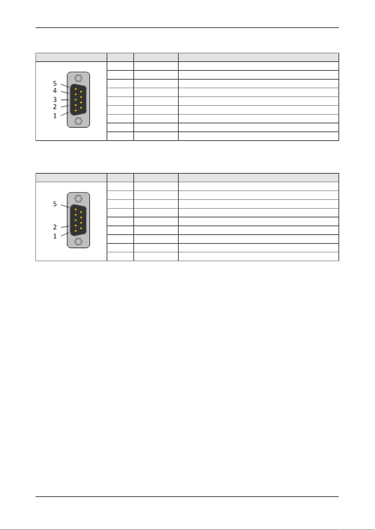
4.7.1 RS-232
RS-232 Pin Signal Description
1 DCD Data Carrier Detect
2 RXD Receive signal
3 TXD Send signal
4 DTR Data Terminal Ready
5 ISO_GND Ground (reference potential)
6 DSR Data Set Ready
7 RTS Request to Send
8 CTS Clear to Send
9 RI Ring Indicator
Table5: RS-232 D-Sub
Edge Gateway | NIOT-E-TIJCX-GB-RE (On-Premise)
DOC160402UM07EN | Revision 7 | English | 2019-07 | Released | Public
© Hilscher 2016 – 2019
Page 16
Connectors and mounting 16/292
4.7.2 RS-422
RS-422 Pin Signal Description
1 Tx‑ Send signal negative
2 Tx+ Send signal positive
3 Rx‑ Receive signal negative
4 Rx+ Receive signal positive
5 ISO_GND Ground (reference potential)
6 n.c. -
7 n.c. -
8 n.c. -
9 n.c. -
Table6: RS-422 D-Sub
4.7.3 RS-485
RS-485 Pin Signal Description
1 Rx/Tx‑ Send/receive signal negative
2 Rx/Tx+ Send/receive signal positive
3 n.c. -
4 n.c. -
5 ISO_GND Ground (reference potential)
6 n.c. -
7 n.c. -
8 n.c. -
9 n.c. -
Table7: RS-485 D-Sub
Edge Gateway | NIOT-E-TIJCX-GB-RE (On-Premise)
DOC160402UM07EN | Revision 7 | English | 2019-07 | Released | Public
© Hilscher 2016 – 2019
Page 17

Connectors and mounting 17/292
4.8 Wi-Fi
The Edge Gateway NIOT-E-TIJCX-GB-RE\WF (article number 1321.301)
is equipped with a Wi-Fi interface. It supports 2 Wi-Fi operating modes:
Access Point and Client. Operating mode Access Point allows the Edge
Gateway to connect to other Wi-Fi devices in order to configure the Edge
Gateway from a mobile device for example. Operating mode Client allows
the Edge Gateway to be connected to any Wi-Fi Access Point.
Section Configuring wireless communication (Wi-Fi) [}page67] describes
how you activate the antennas and how to set the Wi-Fi operating mode.
4.9 Preparing gateway for cellular communication
The NIOT-E-TIJCX-GB-RE\4EU gateway (article number 1321.302) is
equipped with a cellular modem for transmitting data into the cloud via
2G/3G/4G standard.
Requirements
To use the cellular interface of the gateway, you require the following items
(not included in the delivery of the Edge Gateway):
· Contract for mobile data with mobile communications provider
· SIM card of provider with registration credentials (SIM-Pin, password
etc.)
· Two GSM/UMTS/LTE antennas with the following recommended
characteristics (passive):
– Direction: omnidirectional
– Gain: > -3dBi (Avg)
– Input impedance: 50 ohm
– Efficiency: > 50%
– VSWR: < 2
– Connector type: SMA plug
Note:
If you are using the older GSM (2G) standard only, a single (main)
antenna is sufficient.
Edge Gateway | NIOT-E-TIJCX-GB-RE (On-Premise)
DOC160402UM07EN | Revision 7 | English | 2019-07 | Released | Public
© Hilscher 2016 – 2019
Page 18
Connectors and mounting 18/292
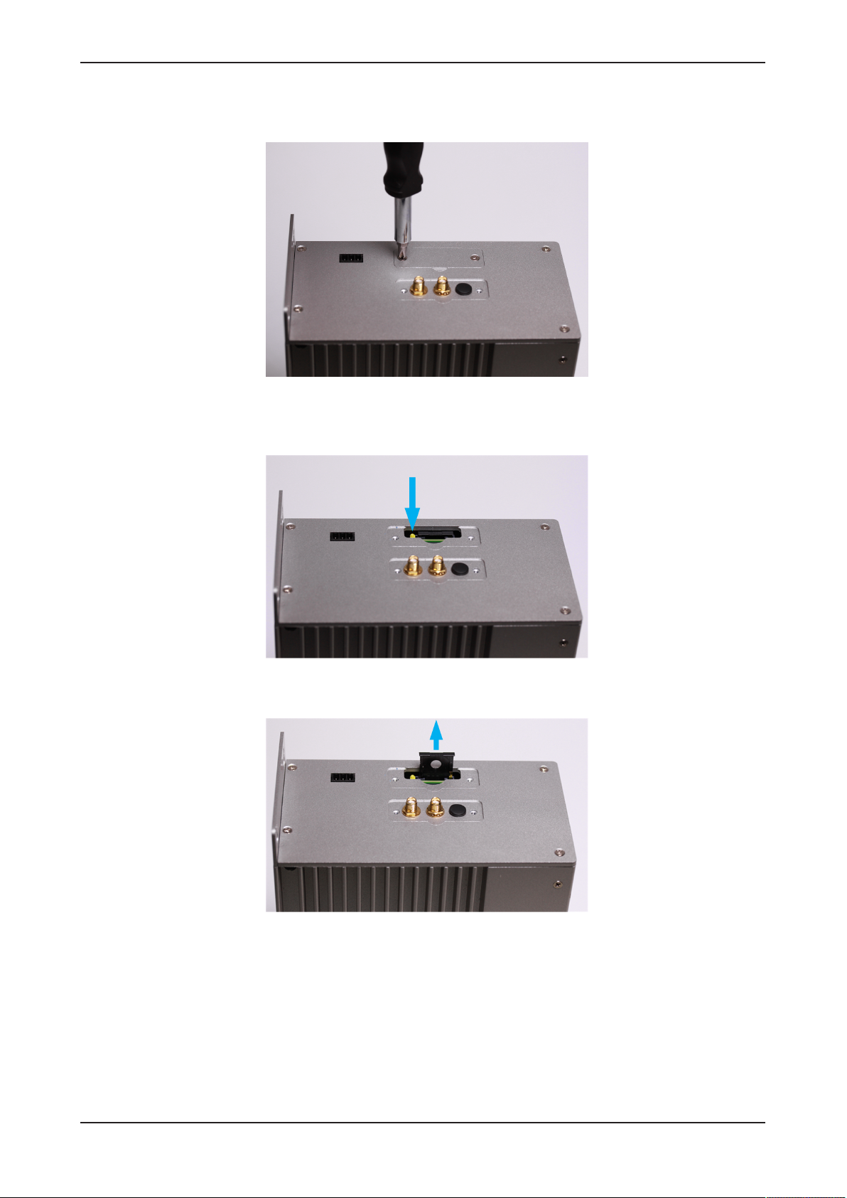
Installing SIM card in gateway
Ø Remove the screws and the cover of the card holder slot:
Figure6: Removing cover of card holder slot
Ø Press the little yellow button with your screwdriver to release the SIM
card holder tray. The tray is thereby slightly ejected in upward direction:
Figure7: Releasing SIM card holder tray
Ø Pull the SIM card tray out of the slot:
Figure8: Pulling out SIM card holder tray
Edge Gateway | NIOT-E-TIJCX-GB-RE (On-Premise)
DOC160402UM07EN | Revision 7 | English | 2019-07 | Released | Public
© Hilscher 2016 – 2019
Page 19
Connectors and mounting 19/292
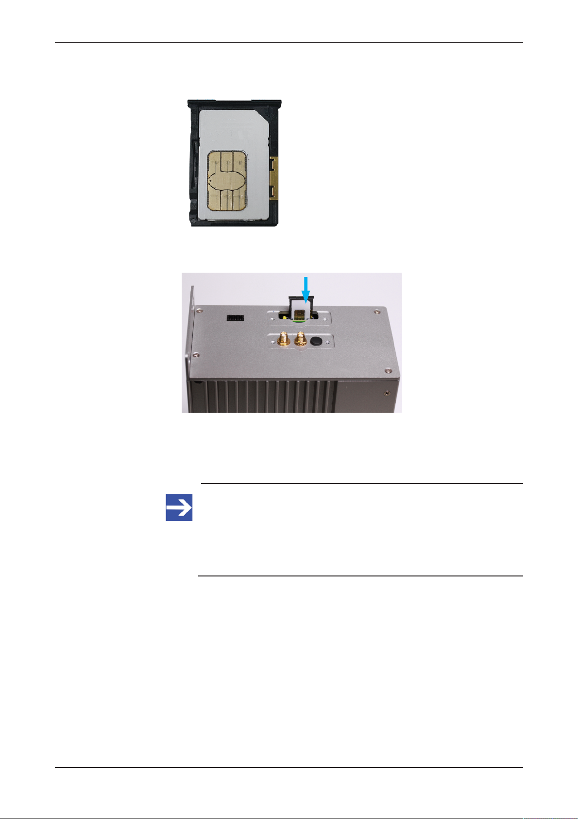
Ø Place the SIM card into the tray. If necessary, use an adapter to fit a
Nano or Micro SIM format into the Mini SIM format of the tray:
Figure9: SIM card in tray
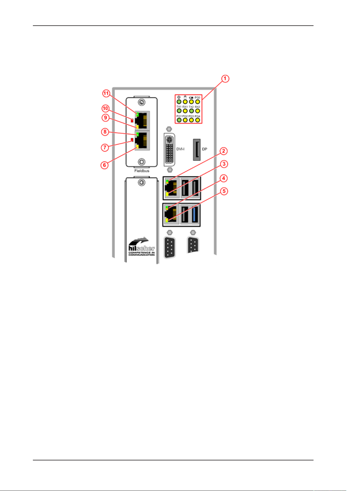
Ø Re-insert the tray with the SIM card into the card holder slot:
Figure10: Inserting SIM card
Ø Re-attach the cover of the card holder slot.
Connecting the antennas
Note:
Recommended type and positioning of your antennas depend on
the quality of your local radio signal.
If your Edge Gateway is stationed inside a control cabinet, you
should place the antennas outside the cabinet and connect the
antennas via cable to the SMA sockets of the gateway.
Edge Gateway | NIOT-E-TIJCX-GB-RE (On-Premise)
DOC160402UM07EN | Revision 7 | English | 2019-07 | Released | Public
© Hilscher 2016 – 2019
Page 20

Connectors and mounting 20/292
Ø Connect both antennas to the SMA sockets of the gateway:
Figure11: SMA sockets
Note:
If you are using solely the older GSM (2G) standard, you need only
one antenna, which is to be connected at the "main" interface of the
two SMA sockets. For identifying the main antenna interface on the
gateway, see section Positions of the interfaces [}page10].
4.10 Monitor connectors
The Edge Gateway has a DVI-I and a DP connector to connect a monitor.
You do not need a monitor for „normal“ operation of the Edge Gateway. If
you want to change settings in the BIOS or want to do a firmware recovery,
you need a monitor.
Important:
Use only 1:1 DVI or DP connectors. Adapters like DVI-I to VGA or
DP to VGA are not supported by the gateway.
Edge Gateway | NIOT-E-TIJCX-GB-RE (On-Premise)
DOC160402UM07EN | Revision 7 | English | 2019-07 | Released | Public
© Hilscher 2016 – 2019
Page 21
LEDs 21/292
5 LEDs
5.1 Positions of the LEDs on the gateway
Figure12: Positions of the LEDs on NIOT-E-TIJCX-GB-RE
Edge Gateway | NIOT-E-TIJCX-GB-RE (On-Premise)
DOC160402UM07EN | Revision 7 | English | 2019-07 | Released | Public
© Hilscher 2016 – 2019
Page 22
LEDs 22/292
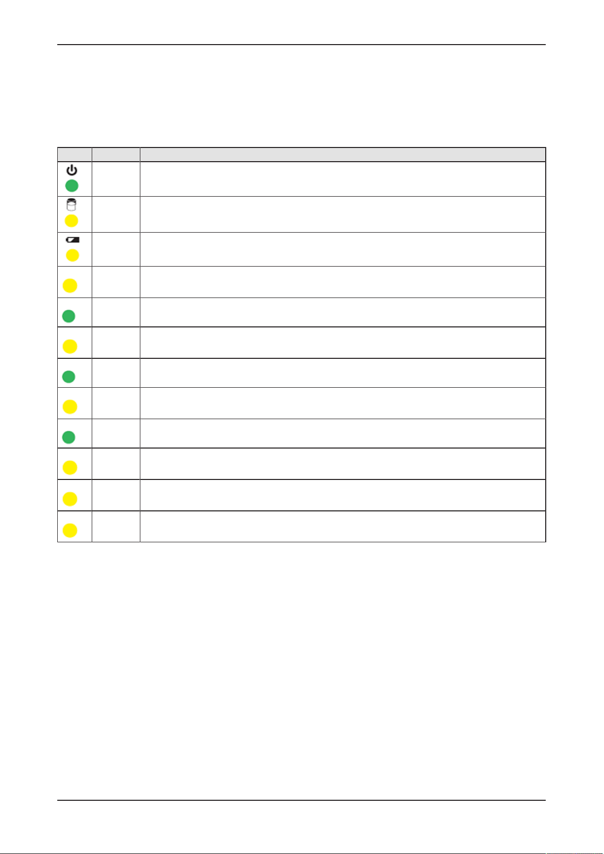
5.2 Gateway status LEDs
LEDs indicating voltage supply, hard disk access, battery state and activity
of operating system, serial interfaces and GPIOs. The position of the LEDs
is indicated by position (1) in section Positions of the LEDs on the
gateway [}page21].
LED Color Meaning
green Voltage supply is OK
yellow Hard disk drive is accessed
yellow State of CMOS-RAM (BIOS) battery
PG0 yellow GPIO 4: can be programmed, currently not used.
TX1 green Transmission of data at serial interface COM1
RX1 yellow Receiving data at serial interface COM1
TX2 green Transmission of data at serial interface COM2
RX2 yellow Receiving data at serial interface COM2
PG1 green GPIO 0. Blinks when data is being copied from USB stick into gateway during firmware recovery.
PG2 yellow GPIO 1: can be programmed, currently not used.
PG3 yellow GPIO 2: can be programmed, currently not used.
PG4 yellow GPIO 3: can be programmed, currently not used.
Table8: Description of gateway status LEDs
Edge Gateway | NIOT-E-TIJCX-GB-RE (On-Premise)
DOC160402UM07EN | Revision 7 | English | 2019-07 | Released | Public
© Hilscher 2016 – 2019
Page 23
LEDs 23/292
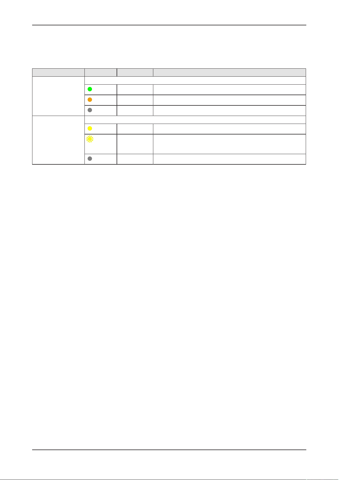
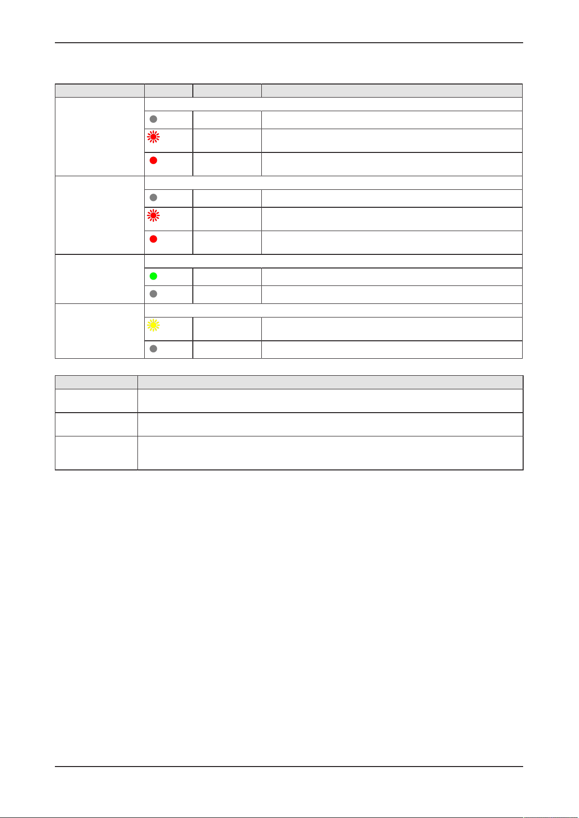
5.3 LEDs of the LAN interface
LEDs indicating state of the LAN communication. For the positions of the
LAN LEDs, see section Positions of the LEDs on the gateway [}page21].
LED Color State Meaning
LINK
See positions (2) and
(4)
RX/TX
See positions (3) and
(5)
Duo LED green/orange
(green)
(orange)
(off)
LED yellow
(yellow)
(yellow)
(off)
Table9: LEDs LAN interface
On 1 GBit network connection
On 100 MBit network connection
Off 10 MBit or no network connection
On The device does not send/receive Ethernet frames.
Flickering
(load
dependent)
Off The device does not send/receive Ethernet frames.
The device sends/receives frames.
Edge Gateway | NIOT-E-TIJCX-GB-RE (On-Premise)
DOC160402UM07EN | Revision 7 | English | 2019-07 | Released | Public
© Hilscher 2016 – 2019
Page 24
LEDs 24/292
5.4 LEDs of the PROFINET IO Device interface
LED Color State Meaning
SF (System Failure)
Position in the device
drawing: (10)
BF (Bus Failure)
Position in the device
drawing: (7)
LINK
CH0 (11) , CH1 (8)
RX/TX
CH0 (9) , CH1 (6)
Duo LED red/green
(off)
(red)
(red)
Duo LED red/green
(off)
(red)
(red)
LED green
(green)
(off)
LED yellow
(yellow)
(off)
Table10: LED states for the PROFINET IO-Device protocol
(Off) No error
Flashing
(1 Hz, 3 s)
On Watchdog timeout; channel, generic or extended diagnosis
Off No error
Flashing
(2 Hz)
On No configuration;
On The device is linked to the Ethernet.
Off The device has no link to the Ethernet.
Flickering (load
dependent)
Off The device does not send/receive Ethernet frames.
DCP signal service is initiated via the bus.
present; system error
No data exchange
or low speed physical link; or no physical link
The device sends/receives Ethernet frames.
LED state Definition
Flashing
(1 Hz, 3 s)
Flashing
(2 Hz)
Flickering (load
dependent)
The indicator turns on and off for 3 seconds with a frequency of 1 Hz:
“on” for 500 ms, followed by “off” for 500 ms.
The indicator turns on and off with a frequency of 2 Hz:
“on” for 250 ms, followed by “off” for 250 ms.
The indicator turns on and off with a frequency of approximately 10 Hz to indicate high Ethernet
activity: "on" for approximately 50 ms, followed by "off" for 50 ms. The indicator turns on and off in
irregular intervals to indicate low Ethernet activity.
Table11: LED state definitions for the PROFINET IO-Device protocol
Edge Gateway | NIOT-E-TIJCX-GB-RE (On-Premise)
DOC160402UM07EN | Revision 7 | English | 2019-07 | Released | Public
© Hilscher 2016 – 2019
Page 25

LEDs 25/292
5.5 LEDs of the EtherNet/IP Adapter interface
LED Color State Meaning
MS
(module status)
Position in the device
drawing: (10)
NS
(Network status)
Position in the device
drawing: (7)
Duo LED red/green
(green)
(green)
(green/red/
green)
(red)
(red)
(off)
Duo LED red/green
(green)
(green)
(green/red/off)
(red)
(red)
On Device operational: The device is operating correctly.
Flashing (1 Hz) Standby: The device has not been configured.
Flashing
green/red/
green
Flashing (1 Hz) Major recoverable fault: The device has detected a major
On Major unrecoverable fault: The device has detected a major
Off No power: The device is powered off.
On Connected: An IP address is configured, at least one CIP
Flashing (1 Hz) No connections: An IP address is configured, but no CIP
Flashing
green/red/off
Flashing (1 Hz) Connection timeout: An IP address is configured, and an
On Duplicate IP: The device has detected that its IP address is
Self-test: The device is performing its power-up testing.
The module status indicator test sequence occurs before the
network status indicator test sequence, according to the
following sequence:
· Network status LED off.
· Module status LED turns green for approximately 250 ms,
turns red for approximately 250 ms, and again turns green
(and holds that state until the power-up test has completed).
· Network status LED turns green for approximately 250 ms,
turns red for approximately 250 ms, and then turns off (and
holds that state until the power-up test has completed).
recoverable fault. E.g., an incorrect or inconsistent
configuration can be considered a major recoverable fault.
unrecoverable fault.
connection (any transport class) is established, and an
Exclusive Owner connection has not timed out.
connections are established, and an Exclusive Owner
connection has not timed out.
Self-test: The device is performing its power-up testing. Refer
to description for module status LED self-test.
Exclusive Owner connection for which this device is the target
has timed out.
The network status indicator returns to steady green only
when all timed out Exclusive Owner connections are
reestablished.
already in use.
(off)
LINK
CH0 (11), CH1 (8)
ACT
CH0 (9), CH1 (6)
Edge Gateway | NIOT-E-TIJCX-GB-RE (On-Premise)
DOC160402UM07EN | Revision 7 | English | 2019-07 | Released | Public
LED green
(green)
(off)
LED yellow
(yellow)
(off)
Table12: LED states for the EtherNet/IP Adapter protocol
(Off) Not powered, no IP address: The device does not have an
IP address (or is powered off).
On The device is linked to the Ethernet.
Off The device has no link to the Ethernet.
Flickering (load
dependent)
Off The device does not send/receive Ethernet frames.
The device sends/receives Ethernet frames.
© Hilscher 2016 – 2019
Page 26

LEDs 26/292
LED state Definition
Flashing
(1 Hz)
Flashing
green/red/
green
Flashing
green/red/off
Flickering
(load
dependant)
Table13: LED state definitions for the EtherNet/IP Adapter protocol
The indicator turns on and off with a frequency of 1 Hz: “on” for 500 ms,
followed by “off” for 500 ms.
The MS LED indicator turns on green on for 250 ms, then red on for 250 ms,
then green on (until the test is completed).
The NS LED indicator turns on green on for 250 ms, then red on for 250 ms,
then off (until the test is completed).
The indicator turns on and off with a frequency of approximately 10 Hz to
indicate high Ethernet activity: on for approximately 50 ms, followed by off
for 50 ms. The indicator turns on and off in irregular intervals to indicate low
Ethernet activity
Edge Gateway | NIOT-E-TIJCX-GB-RE (On-Premise)
DOC160402UM07EN | Revision 7 | English | 2019-07 | Released | Public
© Hilscher 2016 – 2019
Page 27
Commissioning the Edge Gateway 27/292
6 Commissioning the Edge Gateway
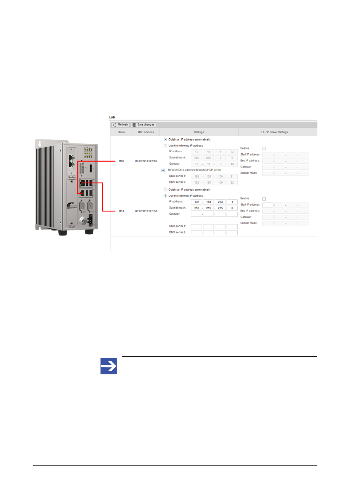
6.1 Establishing the IP address communication
An IP address is required to address the Edge Gateway in the LAN
network.
The following figure shows the factory setting of the LAN interfaces and the
assignment to the connectors.
Figure13: Default settings of the Ethernet network connectors
You have two possibilities of establishing a connection with the Edge
Gateway (factory setting):
NetNetwork connection - alternative 1: DHCP server available
If a DHCP server is available in the network:
Ø Use an Ethernet cable to connect the LAN connection port 1 (eth0)
(see position (7) in section Positions of the interfaces [}page10]) with a
network in which a DHCP server is available.
ð The Edge Gateway obtains an IP address from the DHCP server.
Access to the Edge Gateway is possible now.
Note:
The Edge Gateway sends a request to a DHCP server once after
switching on the device or after each connection of the Ethernet
cable, i.e. when the Edge Gateway detects a link signal. If you want
to activate a request of the Edge Gateway to the DHCP server
manually, pull off the Ethernet cable from the Edge Gateway and
reconnect it to the Edge Gateway.
Read section Using the web browser to establish a connection with the
Edge Gateway [}page29] to find out how to access the Edge Gateway.
Edge Gateway | NIOT-E-TIJCX-GB-RE (On-Premise)
DOC160402UM07EN | Revision 7 | English | 2019-07 | Released | Public
© Hilscher 2016 – 2019
Page 28
Commissioning the Edge Gateway 28/292
Network connection - alternative 2: Direct connection and adaptation
of the IP address of the PC or notebook used for commissioning
The IP address of the Edge Gateway (factory setting) is 192.168.253.1
and the subnet mask is 255.255.255.0 at LAN connection port 2 (eth1,
see position (5) in section Positions of the interfaces [}page10]).
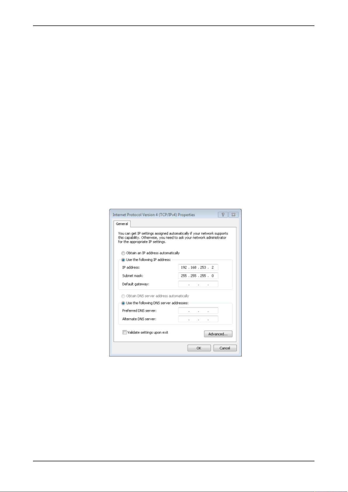
If no DHCP server is available, you can set an IP address on your PC or
notebook, which suits the same subnet:
Ø Use an Ethernet cable to connect the LAN connection port 2 (eth1)
directly with your PC or notebook.
Ø Open the Control panel.
Ø Click on Network and Sharing Center.
Ø Click on Change adapter settings.
Ø Double click the name of the network connection: Local Area
Connection. (The name of the network connection may be different on
your PC.)
Ø Click on Properties.
Ø Double click on Internet Protocol Version 4 (TCP/IPv4).
Ø Set the following IP address, e.g. 192.168.253.2 and subnet mask
255.255.255.0.
Ø Click on Ok and then click on Close.
ð Now you can access the Edge Gateway from your PC or notebook.
Read section Using the IP address [}page31] to find out how to access
the Edge Gateway.
Edge Gateway | NIOT-E-TIJCX-GB-RE (On-Premise)
DOC160402UM07EN | Revision 7 | English | 2019-07 | Released | Public
© Hilscher 2016 – 2019
Page 29
Commissioning the Edge Gateway 29/292
6.2 Using the web browser to establish a connection with the Edge Gateway
You have three possibilities to access the Edge Gateway:
1. by means of the host name (see section Using the host
name [}page29])
2. by access via the Windows network (see section Access to the Edge
Gateway in the Windows network environment [}page30]),
3. by using the IP address (see section Using the IP
address [}page31]).
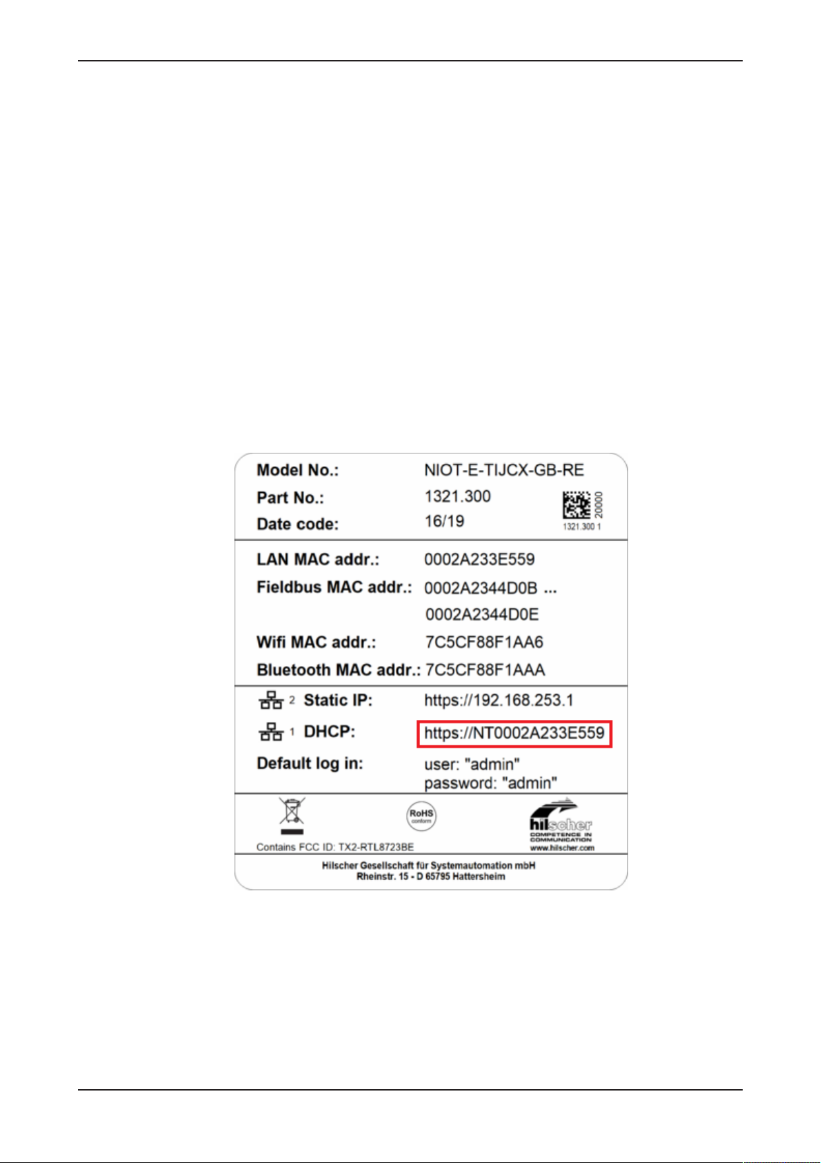
6.2.1 Using the host name
The Edge Gateway has a host name you can use to access the device.
Where do you find the host name on the device?
The device is delivered (factory setting) with a label printed at its bottom. In
the figure below the host name has a red frame.
Figure14: Device label: Hostname
Edge Gateway | NIOT-E-TIJCX-GB-RE (On-Premise)
DOC160402UM07EN | Revision 7 | English | 2019-07 | Released | Public
© Hilscher 2016 – 2019
Page 30

Commissioning the Edge Gateway 30/292
Establishing a connection with the host name
Ø Enter the following address in the address line of your browser:
https://<hostname>
Example: For the device with the host name NTB827EB1D9D94 enter
https:// NTB827EB1D9D94
ð The Edge Gateway Manager opens.
You can now use the Edge Gateway manager to configure the device. For
this purpose, read section Edge Gateway Manager web page [}page33].
6.2.2 Access to the Edge Gateway in the Windows network environment
To be located easily in the network, the Edge Gateway uses the UPnP
technology (Universal Plug and Play). This technology will display the Edge
Gateway in the Windows network environment.
Ø To display all devices in the network, click on Network in the Windows
Explorer.
Ê You will find the Edge Gateway under Other Devices:
Ø Open the context menu of this entry and select Properties.
Ê The menu provides information on the Edge Gateway, e.g. serial
number, MAC address, host name or die IP address.
Ø Click on the link under Device web page.
ð The Edge Gateway manager opens.
Ø To open the Edge Gateway manager, you can also double-click on the
device icon.
ð The Edge Gateway manager opens.
You can now use the Edge Gateway manager to configure the device. For
this purpose, read section Edge Gateway Manager web page [}page33].
Edge Gateway | NIOT-E-TIJCX-GB-RE (On-Premise)
DOC160402UM07EN | Revision 7 | English | 2019-07 | Released | Public
© Hilscher 2016 – 2019
Page 31

Commissioning the Edge Gateway 31/292
6.2.3 Using the IP address
If you know the IP address of one of the LAN connections of the Edge
Gateway and if you are physically connected to your operating device, you
can use your web browser to establish a connection with the Edge
Gateway by entering this IP address directly. Should your operating device
be configured with an IP address only, but without a subnet mask, your
operating device has to be located in the same subnet as the Edge
Gateway to be able establish a connection.
Ø Enter the IP address in the address line of the web browser as follows:
https://<IP address>
Example: https://10.11.5.61
ð The Edge Gateway manager opens.
You can now use the Edge Gateway manager to configure the device. For
this purpose, read section Edge Gateway Manager web page [}page33].
Edge Gateway | NIOT-E-TIJCX-GB-RE (On-Premise)
DOC160402UM07EN | Revision 7 | English | 2019-07 | Released | Public
© Hilscher 2016 – 2019
Page 32

Edge Gateway Manager 32/292
7 Edge Gateway Manager
7.1 Calling the Edge Gateway Manager
The Edge Gateway manager is a web page with tiles that allow rapid
access to the applications integrated in the device or to external web
pages.
The Edge Gateway uses the secured HTTPS protocol to access web pages
stored in the Edge Gateway.
Ø To open the Edge Gateway manager, enter the following information in
the address line of your browser:
https://<Host name of the Edge Gateway>
or
https://<IP address of the Edge Gateway>
ð Your browser displays the Edge Gateway manager.
Figure15: Edge Gateway Manager
Note:
Remember that the secured HTTPS protocol is used here, not the
widely spread HTTP protocol.
Edge Gateway | NIOT-E-TIJCX-GB-RE (On-Premise)
DOC160402UM07EN | Revision 7 | English | 2019-07 | Released | Public
© Hilscher 2016 – 2019
Page 33

Edge Gateway Manager 33/292
7.2 Edge Gateway Manager web page
The Edge Gateway Manager displays tiles that allow rapid access to the
applications integrated in the device or external web pages.
Icon Function
Opens the control panel of the Edge Gateway.
The control panel configures the Edge Gateway and displays
information on the system. Section Control Panel [}page35]
describes the possibilities of configuration as well as the displayed
information on the system.
Opens the wiring editor Node-RED.
Section Node-RED - The wiring editor [}page97]describes how
to create applications for the Edge Gateway.
Opens the Node-RED Dashboard (graphical user interface).
Opens the Edge Server Control Center.
See section Edge Server [}page196].
Opens the Docker management.
See section Isolated application execution with
Docker [}page208].
Opens the Edge Gateway documentation stored in the device.
Opens the homepage of the Device Information Portal in the
Internet.
Requires a connection to the Internet.
Edge Gateway | NIOT-E-TIJCX-GB-RE (On-Premise)
DOC160402UM07EN | Revision 7 | English | 2019-07 | Released | Public
© Hilscher 2016 – 2019
Page 34

Edge Gateway Manager 34/292
Icon Function
Opens the homepage of the netIOT platform in the Internet.
Requires a connection to the Internet.
Opens the Hilscher homepage in the Internet.
Requires a connection to the Internet.
Table14: Starting applications with the Edge Gateway Manager
Edge Gateway | NIOT-E-TIJCX-GB-RE (On-Premise)
DOC160402UM07EN | Revision 7 | English | 2019-07 | Released | Public
© Hilscher 2016 – 2019
Page 35

Control Panel 35/292
8 Control Panel
8.1 Opening the control panel
With the control panel you can configure the Edge Gateway and display
device-specific information.
Ø Click the tile Control Panel.
Ø The login screen for the Control Panel is displayed.
Ø Enter your user name and your password.
Ø Click at Login.
ð The Control Panel will be displayed.
Edge Gateway | NIOT-E-TIJCX-GB-RE (On-Premise)
DOC160402UM07EN | Revision 7 | English | 2019-07 | Released | Public
© Hilscher 2016 – 2019
Page 36

Control Panel 36/292
8.1.1 First login
Setting the administrator password when the control panel is called
for the first time
The dialog box Set Administrator Password is displayed when the control
panel is called for the first time.
Figure16: Edge Gateway Manager - Setting the administrator password
To set a new administrator password, proceed as follows:
Ø Enter the preset password under Current Password. With the first
commissioning, the password is:
admin
Ø Enter the new administrator password. It must have at least 7
characters. For reasons of safety, Hilscher recommends using
significantly more characters. A strong password consists of upper and
lower case letters, digits and special characters. A quality indicator in
the dialog box evaluates the password.
Weak password Mediocre password Strong password
Ø Click Change Password only after the entered password has been
evaluated as strong.
ð The administrator password for the user account Admin has thus been
changed.
ð As an administrator you can now use the control panel, create further
users in the user management, and assign access rights.
Edge Gateway | NIOT-E-TIJCX-GB-RE (On-Premise)
DOC160402UM07EN | Revision 7 | English | 2019-07 | Released | Public
© Hilscher 2016 – 2019
Page 37

Control Panel 37/292
8.1.2 Secure connection
Edge Gateways support web connections secured by SSH/TSL via
https:// accesses only.
By definition, a secure connection can provide an efficient protection only if
a certificate proves that the server is secure. Only then can running
transactions of the initiating browser and the server be considered as
protected against interception and data theft.
This is why the browser at first inquires a certificate of verification from the
server (Gateway). This certificate proves that the issuer has verified the
security of the server. Each browser provides a preinstalled list of known
authorized issuers of certificates.
Each time the certificate of the server arrives at the browser, the browser
compares the issuer of the certificate with the issuers stored in the list of
known authorized issuers of certificates.
If the issuer of the certificate is not listed, the browser will signal a
certificate error and request the user's confirmation to continue because it
assumes that the connection is insecure.
As standard, Edge Gateways contain a certificate issued by Hilscher that is
not on the list of the known authorized issuers of certificates. Due to that,
the browser signals an insecure connection and requests the confirmation
to continue. When this confirmation has been given once, any future
connections will be established without further requests.
Note:
In the control panel you can replace this certificate any time by the
certificate of a known authorized issuer of certificates, see section
Uploading and installing own security certificates).
Edge Gateway | NIOT-E-TIJCX-GB-RE (On-Premise)
DOC160402UM07EN | Revision 7 | English | 2019-07 | Released | Public
© Hilscher 2016 – 2019
Page 38

Control Panel 38/292
8.1.2.1 Connection without certificate with Microsoft Internet Explorer
Microsoft Internet Explorer: Edge Gateway Manager will not be
displayed
If you use the Microsoft Internet Explorer and the following page is
displayed, click the option Continue to this web site (not recommended).
Figure17: Security error message of the Internet Explorer
8.1.2.2 Connection without certificate with Firefox
If you use Firefox as a browser, a self-signed certificate will cause the
following error message:
Figure18: Security error message of the Firefox browser (1)
To avoid this message caused by a self-signed certificate, proceed as
follows:
Ø To display the complete message, click Advanced.
Figure19: Security error message of the Firefox browser (2)
Ø To define an exceptional rule that enables the display of the user
interface without repeated error messages, click Add Exception.
Edge Gateway | NIOT-E-TIJCX-GB-RE (On-Premise)
DOC160402UM07EN | Revision 7 | English | 2019-07 | Released | Public
© Hilscher 2016 – 2019
Page 39

Control Panel 39/292
Figure20: Firefox dialog box: Adding exceptional safety rule
Ø To save the setting permanently, check the box Permanently store
this exception.
Ø To save the rule, click Confirm Security Exception.
ð When you open the control panel in future, security messages will no
longer be displayed.
Edge Gateway | NIOT-E-TIJCX-GB-RE (On-Premise)
DOC160402UM07EN | Revision 7 | English | 2019-07 | Released | Public
© Hilscher 2016 – 2019
Page 40

Control Panel 40/292
8.1.2.3 Connection without certificate with Google Chrome
If you use Google Chrome as web browser, you will get the following error
message due to a self-signed certificate.
Figure21: Security error message of Google Chrome (1)
Proceed as follows in order to avoid the following message, which is
caused by a self-signed certificate,
Ø Click at ADVANCED to display the complete message.
Figure22: Security error message of Google Chrome (2)
Ø In order to continue, click at Proceed to ... (unsafe).
ð The Control Panel is displayed.
Edge Gateway | NIOT-E-TIJCX-GB-RE (On-Premise)
DOC160402UM07EN | Revision 7 | English | 2019-07 | Released | Public
© Hilscher 2016 – 2019
Page 41

Control Panel 41/292
8.2 Overview and main menu
The following figure displays the main menu of the Control Panel.
Figure23: Main menu of the Control Panel
Menu Description Details in section
System > Info Center Displaying the system information, monitoring of
the processor core temperature, and a system
monitor for the usage of CPU, main memory, and
SSD.
System > License Manager Display of activated licenses, upload and
download of the license file.
System > Syslog Displaying the system log files. Displaying the system log
System > Time Settings of system time and time synchronization. Setting the system
System > Port Settings Port configuration for HTTP/HTTPS
communication.
System > Backup and Restore Backup and recovery of the files of the Linux
operating system of the Edge Gateway.
System > Reboot Rebooting the Linux operating system of the Edge
Gateway
System > Shutdown Shutting down the Linux operating system of the
Edge Gateway
Package Manager > Packages Managing the packages of the Linux-based
operating system of the Edge Gateway.
Network > LAN Configuring the Ethernet interfaces to the IT
network and OT network (fieldbus).
Network > Wi-Fi Configuring the Wi-Fi communication Configuring wireless
Network > Field Configuring the operating mode of the fieldbus
interface (Real-Time Ethernet).
Network > Cellular Configuration of the cellular interface. Configuring cellular
Network > Routes Configuration of interfaces or connections for
certain IP destination addresses.
Network > Firewall Firewall configuration for each interface or
connection.
Network > Hostname Displaying and configuring the host name
identifying the Edge Gateway in the network.
Services > Service List Displaying, starting, and stopping the services of
the Edge Gateway.
User Management > Roles Displaying and configuring the permissions for
user roles.
User Management > Accounts Displaying user accounts und assigning user
roles.
Security > Public Key
Infrastructure
Help > Info Displaying current software version.
Session > User Profile Displaying the permissions of the user.
Session > Logout Logout
Store and administer certificates and key files
within the Public Key Infrastructure
Table15: Functional overview of the Control Panel
Displaying system
information [}page43]
License Manager [}page44]
files [}page47]
time [}page51]
Configure ports for HTTP/HTTPS
communication [}page53]
Backup and restore [}page55]
Rebooting the
system [}page62]
System shutdown [}page63]
Managing packets [}page63]
Configuring Ethernet
communication
(LAN) [}page64]
communication (WiFi) [}page67]
Field [}page73]
communication [}page74]
Configuring IP
Routes [}page78]
Configuring Firewall [}page82]
Hostname [}page84]
Starting, stopping and configuring
services [}page85]
Managing user roles [}page89]
Managing user
accounts [}page91]
Public Key
Infrastructure [}page92]
Help [}page95]
User profile [}page95]
Logout [}page96]
Edge Gateway | NIOT-E-TIJCX-GB-RE (On-Premise)
DOC160402UM07EN | Revision 7 | English | 2019-07 | Released | Public
© Hilscher 2016 – 2019
Page 42

Control Panel 42/292
For the pages which can be invoked via the Control Panel, the following
applies:
If for the selected page, no access right for reading is present, this has the
following implications:
· No data are displayed. All important controls and displays of the page
are grayed out respectively inactive.
· The error message Permission denied is displayed when accessing
the page.
If there is read but no write access right present, this has the following
implications:
· The error message Permission denied is displayed when trying to
make a change.
Edge Gateway | NIOT-E-TIJCX-GB-RE (On-Premise)
DOC160402UM07EN | Revision 7 | English | 2019-07 | Released | Public
© Hilscher 2016 – 2019
Page 43

Control Panel 43/292
8.3 System information and system time
8.3.1 Displaying system information
Open this page with System > Info Center. No access rights are required
in order to open this page. This page shows e.g. the firmware version and
the serial number of the Edge Gateway.
Figure24: Page Info Center
The Info Center displays the following information:
System info Description
Hardware ident. Serial number of the Edge Gateway
Model name Model designation of the Edge Gateway (NIOT-E-TIJCX-GB-RE)
Firmware version Complete version designation of the firmware stored in the Edge
Gateway
System time Synchronization status of the internal clock of the Edge Gateway.
When the clock is synchronized via the network, the IP address and
the name of the time server used for synchronization will be
displayed. The user has to configure the time zone.
Processor name Name of the microprocessor (CPU) installed in the Edge Gateway.
Table16: Info Center: Area System info
Edge Gateway | NIOT-E-TIJCX-GB-RE (On-Premise)
DOC160402UM07EN | Revision 7 | English | 2019-07 | Released | Public
© Hilscher 2016 – 2019
Page 44

Control Panel 44/292
Monitoring Description
CPU usage Number of microprocessor cores plus clock frequency and average
utilization of each core in the Edge Gateway
Memory utilization Size and average utilization of the main memory in the Edge Gateway
Storage space Display of available memory and the memory that is currently utilized
on the integrated Solid-State-Disk of the Edge Gateway
Table17: Info Center: Area Monitoring
Temperature Description
CPU temperature Display of the temperature of each processor core in the Edge
Gateway
Table18: Info Center: Area Temperature
If the data of the area Monitoring cannot be read, this is grayed out.
8.3.2 License Manager
Open this page with System > License Manager.
The functionality of an Edge Gateway can be extended. The use of
particular functions requires a license. On this page you can see which
licenses are present in the device and you can transfer a license file into
the device.
8.3.2.1 Which licenses are present in the device?
In order to display the licenses contained in the Edge Gateway, use the
License Manager. You can open it as follows:
Ø Open the Control Panel.
Ø Select System>License Manager.
Ê The window of the License Manager opens:
Figure25: License Manager with license for the passive mode of operation
The table License enabled Software Packages displays the currently
available licenses, in the example a license for the passive mode of
operation of the Edge Gateways is available.
Edge Gateway | NIOT-E-TIJCX-GB-RE (On-Premise)
DOC160402UM07EN | Revision 7 | English | 2019-07 | Released | Public
© Hilscher 2016 – 2019
Page 45

Control Panel 45/292
Open Details window in the License Manager
To open the Details window:
Ø Click at the info button on the left edge of the line (within column
Details).
Ê The Details window opens:
Figure26: License information in window Details
For each license, it displays the license type (Column Type), a brief
description (Column Description) and the expiration date (Column
Expires). An expiration date will be displayed only, if the license has a runtime limit.
8.3.2.2 How to order and receive a license
The following instruction explains how to order a license for your Edge
Gateway to be used in passive mode of operation and receive a license file.
If you order device and license together or after ordering the license, you
receive a delivery note. After receiving the delivery note order the license
file from Hilscher by e-mail. Specify the following information in your e-mail:
1. The denomination of the desired license
2. The number of your delivery note (for reference)
3. The LAN MAC address of your device (to be taken from the device
label)
4. The e-mail address, to which the license download link shall be sent to.
Specify the following as the subject of your e-mail:
Request for a netIOT Licence
Ø Send the e-mail to Hilscher: vertrieb@hilscher.com
Ø Hilscher creates an individual license file for your Edge Gateway
according to the information supplied by you.
Ø Hilscher sends this file back to you as an attachment within the answer
e-mail. Consequently, this license file has to be transferred into the
Edge Gateway as described in section How to transfer a license into the
device? [}page46].
Edge Gateway | NIOT-E-TIJCX-GB-RE (On-Premise)
DOC160402UM07EN | Revision 7 | English | 2019-07 | Released | Public
© Hilscher 2016 – 2019
Page 46

Control Panel 46/292
8.3.2.3 How to transfer a license into the device?
Load the individual license file received from Hilscher from your PC into the
Edge Gateway. Do the upload as follows:
Ø Open the Control Panel in a web browser.
Ø Select System > License Manager.
Ø Click on Upload License.
Ê A file selection dialog opens.
Ø Select the license file. This file has the file extension *.LIC.
Ø Click on OK.
Ê The license file is transferred into the Edge Gateway. If the transfer is
successful, the following message is displayed:
Figure27: Message after the transfer of the license file into the Edge Gateway
Ê To activate the license, a restart of the Edge Gateways is necessary.
Ø Click on OK.
Ê The license is installed now, but becomes active after the next restart of
the Edge Gateways.
Ø For a restart, select System > Reboot.
ð The license is activated.
Edge Gateway | NIOT-E-TIJCX-GB-RE (On-Premise)
DOC160402UM07EN | Revision 7 | English | 2019-07 | Released | Public
© Hilscher 2016 – 2019
Page 47

Control Panel 47/292
8.3.3 Displaying the system log files
System log service and syslog file
At any time, a Linux system executes many programs running in parallel
within the background. Usually, these are denominated as services, servers
or daemons. They perform a large part of the work of the operating system.
As they run in the background, these programs do not have a GUI and so
they are not able to manage output directly, for instance in case of events
relevant for system administration.
Such messages originate from
1. the Linux kernel (the central part of the operating system)
2. the daemons (programs executing the system services
3. user nprograms
Therefore, these messages are collected by a central system log service
(syslog) and are distributed depending on their priority and origin according
to a configurable set of rules.
So ,for system supervision and safeguarding correct reaction on error
situations, the file logging daemon syslogd (or an improved successor of it)
runs on every Linux system,. On the Edge Gateways from Hilscher, the
widely-spread logging daemon Syslog-ng is used, which had been
developped by BalaBit IT Security Ltd. (now: One Identity, https://syslog-
ng.org/).
Openíng the system log
To access the syslog files generated by Syslog-ng, open this page within
the main menu of the control panel using System > Syslog. Read access
rights are required to open this page. The page shows you a list of stored
system logs covering different periods in time. This list also contains the
last date of change and the file size specified in KB. Within this list, each
line corresponds to a gzip-compressed system log file for a specific time
period.
Figure28: Control Panel, page System > Syslog
Edge Gateway | NIOT-E-TIJCX-GB-RE (On-Premise)
DOC160402UM07EN | Revision 7 | English | 2019-07 | Released | Public
© Hilscher 2016 – 2019
Page 48

Control Panel 48/292
Ø Select the desired entry within table Syslog files.
Ê The selected line is highlighted instantly.
Ø Click at button Download in the header of window Syslog files.
ð Your Web browser loads the file down from the Edge Gateway and
offers options for further processing of the downloaded file such as
Open, Open directory. The file has been compressed with the program
gzip and must be unpacked prior to evaluation.
8.3.3.1 Structure of system log file
The structure of the entries has been originally defined by the IETF within
RFC3164 (https://tools.ietf.org/html/rfc3164), meanwhile it has been
reworked and substituted by RFC5424 (https://tools.ietf.org/html/rfc5424) .
The structure of the entries in the system log files of the Edge Gateways
also follows this structure.
HEADER
PRI - Priority
The header starts with the priority, denominated as PRI within the
standard.The priority is an integer number enclosed by angled brackets like
<45>, for instance.
The priority can be calculated from two numeric values:
· the facility (signifying the origin of the message, located within the upper
5 Bits)
· the severity (signifying the urgence and importance of the message,
located within the lower 3 Bits)
The following formula accomplishes this:
Priority = 8 * Facility + Severity
The facility is coded according to the following table:
Code Facility (Origin of message)
0 Kernel messages
1 User-level message
2 Mail system
3 System daemons
4 Security/authorization messages
5 Messages generated internally by syslogd
6 Line printer subsystem
7 Network news subsystem
8 UUCP subsystem
9 Clock daemon
10 Security/authorization messages
11 FTP daemon
12 NTP subsystem log audit
13 Log audit
14 Log alert
15 Clock daemon
16…23 Locally used facilities (local0-local7)
Table19: Numeric coding of facility value in priority PRI
Edge Gateway | NIOT-E-TIJCX-GB-RE (On-Premise)
DOC160402UM07EN | Revision 7 | English | 2019-07 | Released | Public
© Hilscher 2016 – 2019
Page 49

Control Panel 49/292
The severity is coded according to the following table:
Code Severity (Importance of message)
0 Emergency: System is currently in an unusable state
1 Alert: Immediate action required
2 Critical: The system is in a critical state
3 Error: Error messages are present
4 Warning: Warning messages are present.
5 Notice: Normal state of operation, but there is an important Information
6 Informational: Informational messages are present
7 Debug: Messages on debug level are present
Table20: Numeric coding of severity value in priority (PRI)
VERSION
ISOTIMESTAMP
HOSTNAME
APPLICATION
PID
MESSAGEID
Here the version number of the current sys´log protocol standard is put out.
As this is still in version 1, the version without any exception always equals
to 1.
This part of the message line contains a timestamp in ISO 8601-compatible
standard format (yyyy-mm-ddThh:mm:ss+-ZONE). This time stamp
relates to the point in time at that the message has been generated.
Example
07/06/2018 15:59:41
This part of the message line contains the name of the machine originally
sending the message. The length of HOSTNAME is limited to 255
characters.
This part of the message line contains the name of the device or application
originally generating the message. The length of APPLICATION is limited
to 48 characters.
This part of the message line contains the name of the process or the
process ID of the syslog application originally sending the message. This
may not necessarily be the process ID of the application generating the
message. The length of PID is limited to 128 characters.
This is the ID of the message itself. The length of MESSAGEID is limited to
32 characters.
This part of the message line may contain metadata on the message line or
application-specific information such as counters or IP addresses. It
consists of data blocks enclosed in angled brackets []. Each block contains
an ID and one or more pairs of the form name=value.
Example
[meta sequenceId="1"]
MSG
This part of the message line contains the genuine text of the message. It
can either be coded in UTF-8 (if a BOM character has been detected) or
otherwise it is ASCII-coded.
Edge Gateway | NIOT-E-TIJCX-GB-RE (On-Premise)
DOC160402UM07EN | Revision 7 | English | 2019-07 | Released | Public
© Hilscher 2016 – 2019
Page 50

Control Panel 50/292
Example of complete message line
A message line may look as follows:
<45>1 2018-07-06T13:59:41+00:00 localhost syslog-ng 1524 - [meta
sequenceId="1"] syslog-ng starting up; version='3.8.1'
The following table shows the assignment of the parts of this specific
message line:
Part of message line Corrresponding denomination
<45> PRI (Priority)
1 VERSION (Versions number of current syslog
protocol standard)
2018-07-06T13:59:41+00:00 ISOTIMESTAMP
localhost HOSTNAME
syslog-ng APPLICATION
1524 PID (Process name or process D ofsyslog
application sending the message)
- MESSAGEID
[meta sequenceId="1"] STRUCTURED-DATA (Meta information)
syslog-ng starting up;
version='3.8.1'
Table21: Assignment of parts of message line
MSG (Real message text)
8.3.3.2 Log rotation
The Edge Gateway is configured for a daily change of the logging file and
to keep the files of the last seven days. This procedure is denominated as
log rotation.
Edge Gateway | NIOT-E-TIJCX-GB-RE (On-Premise)
DOC160402UM07EN | Revision 7 | English | 2019-07 | Released | Public
© Hilscher 2016 – 2019
Page 51

Control Panel 51/292
8.3.4 Setting the system time
Open this page with System > Time.
To access this page, you need rights for the resource:
Setting the system time
On this page you can set the system time and the time zone this time
relates to.
You can set the system time in two ways:
Type Selection Method Standard
presetting
manually Manual selection by entering date and time no.
automatically NTP synchronized by means of a time server yes
Table22: Setting the system time
Figure29: Time configuration page
Note:
When you change a system time setting, always reboot the Edge
Gateway afterwards so that all software components in the Edge
Gateway take the changed time: System > Reboot.
Edge Gateway | NIOT-E-TIJCX-GB-RE (On-Premise)
DOC160402UM07EN | Revision 7 | English | 2019-07 | Released | Public
© Hilscher 2016 – 2019
Page 52

Control Panel 52/292
Setting the system time manually
Ø Click the option Manual.
Ø Enter the time in the input field Time in the format hh:mm:ss.
Ø Set the date using the calendar input field Date.
Ø Click Save changes.
Ø Reboot the device: System > Reboot in order that all software
components in the Edge Gateway take the changed time.
ð The system time is set.
Setting the system time automatically using a time server
You can synchronize the time using a time server that uses the Network
Time Protocol (NTP). Under NTP synchronized there is a list where you
can enter such time servers. The list of NTP servers will be worked off from
top to bottom until a server gives a valid answer and synchronization
occurs.
Ø Click the option NTP Synchronized.
Ø Click Add NTP server.
Ê The dialog box for entering the NTP server is displayed.
Ø In the input field NTP server enter the address of a server which uses
the NTP to synchronize the time:
E.g.: To add the server for time synchronization of the PhysikalischTechnische Bundesanstalt (the National Metrology Institute of
Germany) to the list, enter the address ptbtime1.ptb.de in the input
field NTP server.
Ø Click Add.
Ø Click Save changes.
Ø Reboot the device: System > Reboot in order that all software
components in the Edge Gateway take the changed time.
ð The system time is set via the NTP. As soon as the system time is set
successfully, the following information will be displayed under Status:
Synchronized to time server <IP address of the time
server>:<Port number of the time server > (<NTP
address of the time server>)
Edge Gateway | NIOT-E-TIJCX-GB-RE (On-Premise)
DOC160402UM07EN | Revision 7 | English | 2019-07 | Released | Public
© Hilscher 2016 – 2019
Page 53

Control Panel 53/292
Setting the time zone
With the selection list Timezone you can adjust the time zone to your local
time in which the Edge Gateway is so that the set time can be interpreted
correctly (e.g. summer time conversion). For this purpose, the selection list
Timezone offers many setting options. The default value is Universal. For
Central European Time set CET.
Note:
Once the system time has been set, system services and NodeRED flows which use the system time for synchronization loose
their reference time, i.e. they refer to the new time set. When you
change a system time setting, always reboot the Edge Gateway
afterwards so that all software components in the Edge Gateway
take the changed time.
8.3.5 Configure ports for HTTP/HTTPS communication
Open this page with System > Port Settings.
In order to open this page, no access rights are required.
By default, the Edge Gateway Manager uses port 80 for its HTTP
communication and port 443 for its HTTPS communication. In case of the
ports being used otherwise, you can configure the Edge Gateway to use
other ports. This situation applies, for instance, when using Docker (see
Isolated application execution with Docker [}page208]) , if Docker
containers are designed to serve HTTP and HTTPS requests only at the
above mentioned standard ports.
Figure30: Port settings
Protocol Default port
HTTP 80
HTTPS 443
Table23: Default ports
Edge Gateway | NIOT-E-TIJCX-GB-RE (On-Premise)
DOC160402UM07EN | Revision 7 | English | 2019-07 | Released | Public
© Hilscher 2016 – 2019
Page 54

Control Panel 54/292
Setting port address for HTTP
Ø Enter the port address for the communication of the Edge Gateway
Manager over HTTP in input field HTTP Port.
Ø Store the port address as described subsequently. If a red error
message box with the text http port is not free appears, the port is
already used. In this case select another port.
Setting port address for HTTPS
Ø Enter the port address for the communication of the Edge Gateway
Manager over HTTPS in input field HTTPS Port.
Ø Store the port address as described subsequently. If a red error
message box with the text https port is not free appears, the port is
already used. In this case select another port.
Save changes of port adresses
Ø Click at Save changes in order to permanently store the port address.
Note:
Take care of this change not to have an immediate effect, but being
effective after the next restart of the Edge Gateway.
Refresh
Clicking at the button Refresh, the currently configured values for the port
addresses in the input fields HTTP Port and HTTPS Port are displayed.
Edge Gateway | NIOT-E-TIJCX-GB-RE (On-Premise)
DOC160402UM07EN | Revision 7 | English | 2019-07 | Released | Public
© Hilscher 2016 – 2019
Page 55

Control Panel 55/292
8.3.6 Backup and restore
Open this page by System > Backup and Restore.
You have to login as Administrator to use this function.
This page offers the possibility to store the complete system files of the
Linux operating system of your Edge Gateway onto an external mass
storage device and to restore it from there, if necessary.
Backup
Observe the following information:
· The duration of the backup depends on the quantity of data.
· A running backup cannot be interrupted.
· The backup can deteriorate the performance of the Edge Gateway.
· Save the backup on an external data carrier because any existing
backup will be overwritten irrevocably without prior notice.
In order to create a backup of your system, proceed as follows:
Ø Select System > Backup and Restore in the control panel.
Ê The following screen is displayed:
Figure31: Backup and recovery
Ø Click at Create local backup.
Edge Gateway | NIOT-E-TIJCX-GB-RE (On-Premise)
DOC160402UM07EN | Revision 7 | English | 2019-07 | Released | Public
© Hilscher 2016 – 2019
Page 56

Control Panel 56/292
Ê The following warning message is issued:
Figure32: Warning message
To improve the safety you can optionally define a password within input
field Password. If a password has been specified, that password must be
entered at each attempt to access the created backup file.
Furthermore, this warning message explains the above mentioned
consequences of starting the backup process such as time expense,
increased system load and missing possibility of abortion.
Ø In order to start the backup process, click at Yes.
Ê The following screen indicates the start of the backup process by the
text Backup in progress:
Figure33: Backup in progress
ð If the backup process has successfully been finished, the formerly
grayed out buttonDownload local backup is activated and the backup
file is offered for possible download. This means, the backup of system
files has been completed.
Edge Gateway | NIOT-E-TIJCX-GB-RE (On-Premise)
DOC160402UM07EN | Revision 7 | English | 2019-07 | Released | Public
© Hilscher 2016 – 2019
Page 57

Control Panel 57/292
Recovery from internal backup
Choose this option to restore the system using the stored data, if already
an internal backup has been performed within your device.
Take care of the following consequences of system recovery:
· that the former system is fully replaced and overwritten by the system
stored in the backup file.
· that the system is stopped.
· that a new start of the system is initiated.
· that this process can last for a significant amount of time and cannot be
interrupted.
· that you must not interrupt power supply of the Edge Gateway in
any case.
In order to restore your system from a previous internal backup, proceed as
follows.
Ø Select System>Backup and Restore within the Control Panel..
Ê The following screen appears:
Figure34: Backup and recovery
Ø Click at Restore from backup.
Edge Gateway | NIOT-E-TIJCX-GB-RE (On-Premise)
DOC160402UM07EN | Revision 7 | English | 2019-07 | Released | Public
© Hilscher 2016 – 2019
Page 58

Control Panel 58/292
Ê The following recovery dialog is displayed:
Figure35: Recovery dialog
Ê If there is already an internal backup present in the system, you will
notice that the button Restore is activated.
Note:
If a password has been specified at creation of the backup file to be
restored, that password must be entered in input field Password!
Ø Click at Restore.
Ê The following security query is displayed:
Figure36: Security query prior to system recovery from internal backup file
Ê You are informed about the above mentioned consequences of system
recovery.
Ø If you want to proceed taking into account these consequences, then
click at Yes.
Ø The system on your device is restored from the system files stored
within the internal backup. In any way, do not interrupt the power supply
of the Edge Gateway during system recovery!
Edge Gateway | NIOT-E-TIJCX-GB-RE (On-Premise)
DOC160402UM07EN | Revision 7 | English | 2019-07 | Released | Public
© Hilscher 2016 – 2019
Page 59

Control Panel 59/292
Recovery from external backup
Choose this option to restore the system using the stored data, if already
an internal backup has been performed within your device and you have
downloaded this backup to an external storage medium or device.
Take care of the following consequences of system recovery:
· that the former system is overwritten and fully replaced by the system
stored in the backup file.
· that a new start of the system is initiated.
· that this process can last for a significant amount of time and cannot be
interrupted.
· that you must not interrupt power supply of the Edge Gateway in any
case.
In order to restore your system from a previous external backup (i.e.
download of an internal backup), proceed as follows.
Ø Select System>Backup and Restore within the Control Panel.
Ê The following screen appears:
Figure37: Backup and recovery
Ø Click at Restore from backup.
Edge Gateway | NIOT-E-TIJCX-GB-RE (On-Premise)
DOC160402UM07EN | Revision 7 | English | 2019-07 | Released | Public
© Hilscher 2016 – 2019
Page 60

Control Panel 60/292
Ê The following recovery dialog appears:
Figure38: Recovery dialog (external source)
Note:
If a password has been specified at creation of the backup file to be
restored, that password must be entered in input field Password!
Ø Click at Explorer.
Ê A file selection dialog appears.
Ø Select the image file with your stored system (file extension is *.img).
Ê The following message dialog is displayed:
Figure39: Message prior to starting recovery from external backup
Ê You are informed about the above mentioned consequences of system
recovery.
Ø If you want to proceed taking into account these consequences, then
click at Yes.
ð The selected file is checked for correctness. If the file is no image file,
does not contain a backup or is defective in any other way, an error
message is displayed. Otherwise your system is recovered from
external backup. In any way, do not interrupt the power supply of the
Edge Gateway during system recovery!
Edge Gateway | NIOT-E-TIJCX-GB-RE (On-Premise)
DOC160402UM07EN | Revision 7 | English | 2019-07 | Released | Public
© Hilscher 2016 – 2019
Page 61

Control Panel 61/292
Delete local backup
If you want to delete a locally present internal backup, you can perform this
as follows:
Ø Select menu entry System>Backup and Restore within the Control
Panel.
Ê The following screen appears:
Figure40: Backup and restore when backup file is present
Ø Click at Delete local backup.
Ê The following safety query indicates the danger of possible data loss at
deleting the backup, if it has not externally been saved via the download
function.
Figure41: Safety query before deletion of local backup
Ø If you are still sure, that you really intend to delete the local backup,
click at Yes.
ð The local backup is internally deleted. Right of Local backup the text
No backup is displayed now instead the name of the former backup.
Edge Gateway | NIOT-E-TIJCX-GB-RE (On-Premise)
DOC160402UM07EN | Revision 7 | English | 2019-07 | Released | Public
© Hilscher 2016 – 2019
Page 62

Control Panel 62/292
Downloading a local backup
To download an existing local backup (image file) from the Egde Gateway
to an external data carrier, proceed as follows:
Ø Select System > Backup and Restore in the control panel.
Ê The following screen will be displayed:
Figure42: Backup and Restore
Ø Click Download local backup.
Ø Select a storage location.
ð The download of your backup will be started and the backup will be
stored on the external data carrier.
8.3.7 Rebooting the system
You have to login as Administrator to use this function.
In order to reboot the system:
Ø Within the Control Panel select menu entry System > Reboot
Ê The following safety query is displayed:
Figure43: Reboot safety query
Ø If you really intend to reboot the system, answer to the safety query with
Yes.
ð The Linux operating system of your Edge Gateway is shut down and
then immediately restarted.
Note:
Take care of the consequences of shutting down and restarting for
your network, if you reboot the Edge Gateway.
Edge Gateway | NIOT-E-TIJCX-GB-RE (On-Premise)
DOC160402UM07EN | Revision 7 | English | 2019-07 | Released | Public
© Hilscher 2016 – 2019
Page 63

Control Panel 63/292
8.3.8 System shutdown
You have to login as Administrator to use this function.
In order to shut down the system:
Ø Within the Control Panel select menu entry System > Shutdown.
Ê The following safety query is displayed:
Figure44: Warning for consequences of shutdown
Ø If you really intend to shut down the system, answer to the safety query
with Yes.
ð The Linux operating system of your Edge Gateway is shut down.
Note:
Take care of the consequences for your network, if you shut down
the Edge Gateway.
8.4 Packet management
8.4.1 Managing packets
Open this page with Package Manager > Packages.
In order to be allowed to install packages, you need access rights "Read &
Write" for the resource "packages". In order to view the installes packages,
you only need access right "Read".
This page serves for managing additionally installes packages of the Linuxbased operating system of the Edge Gateway. The standard packages of
the operating system will not be listet on this page. The page
· lists the additionally installed packages including version,
· adds new and signed packages or
· updates already installed signed packages.
Note:
You can install packages signed by Hilscher only!
Use the package management only when Hilscher requests you to use the
package management.
Edge Gateway | NIOT-E-TIJCX-GB-RE (On-Premise)
DOC160402UM07EN | Revision 7 | English | 2019-07 | Released | Public
© Hilscher 2016 – 2019
Page 64

Control Panel 64/292
8.5 Network
8.5.1 Configuring Ethernet communication (LAN)
Open this page with Network > LAN.
For editing the parameters, you need the access right „Read & Write“ to the
resource „LAN“. For displaying the parameters, you need the access right
„Read“.
On this page you configure the Ethernet interfaces eth0, eth1 (both on
the side of the cloud) and cifx0 (on the side of the fieldbus).
When delivered, the Ethernet interface cifx0 is deactivated. Section
„Activating the Ethernet interface cifx0“ (see below) describes how to
activate this interface.
You can configure the setting of the IP-address for each Ethernet interface.
· The Edge Gateway obtains the IP-address parameters automatically
from a DHCP server: Option „Obtain an IP address automatically“. The
Edge Gateway is a DHCP client.
· The user enters the IP-address parameters manually: Option „Use the
following IP address“. In this setting the Edge Gateway can be used as
a DHCP server (optionally).
The IP-address parameters include the IP-address, the subnet mask, the
Gateway address, and the IP-addresses of Domain Name Server 1 and 2.
The default IP address of the LAN connection eth1 (Port 2) is
192.168.253.1 with the subnet mask 255.255.255.0.
Figure45: Default LAN-configuration
Edge Gateway | NIOT-E-TIJCX-GB-RE (On-Premise)
DOC160402UM07EN | Revision 7 | English | 2019-07 | Released | Public
© Hilscher 2016 – 2019
Page 65

Control Panel 65/292
Column Element Description
Name - displays the name of the LAN interface, e.g. eth0.
MAC address - displays the MAC address of the LAN interface.
Settings Obtain an IP address
automatically
Use the following IP
address
IP address,
Subnet mask,
Gateway
Receive DNS address
from DHCP server
DNS server 1,
DNS server 2
DHCP server
settings
Enable
Setting required so that the Edge Gateway automatically obtains the IPaddress parameters from a DHCP server.
Setting required so that the user can enter the IP-address parameters
manually. In addition, always enter the subnet mask and the Gateway
address.
Automatically: Display of the IP-address parameters received from the
DHCP server.
Manually: Input fields for the IP-address parameters to be entered by the
user.
DNS addresses (automatically) received from DHCP server.
DNS addresses manually entered by the user.
Automatically: Display of the DNS addresses received from the DHCP
server.
Manually: Input fields for the DNS addresses to be entered by the user.
At this interface, the Edge Gateway provides a DHCP server.
Prerequisite: The option „Use the following IP address“ is set. Note: In
this subnetwork, no other DHCP server must be available.
At this interface, the DHCP server is deactivated.
Start IP address,
End IP address,
Gateway,
Subnet mask
Table24: Table LAN: Description of the columns and elements
Parameters for the integrated DHCP server of the Edge Gateway.
To save your changes permanently, click Save changes.
Edge Gateway | NIOT-E-TIJCX-GB-RE (On-Premise)
DOC160402UM07EN | Revision 7 | English | 2019-07 | Released | Public
© Hilscher 2016 – 2019
Page 66

Control Panel 66/292
Activating the Ethernet interface cifx0
1. Selecting the operating mode and firmware
Ø Open the Fieldbus page with Network > Field.
Ê The Fieldbus page is displayed.
Ø Set the operating mode to Active.
Ø Click Change mode and then Yes.
Ø Under Firmware, select PROFINET IO Device or EtherNet/IP Adapter.
Ø If you have changed the selection under Firmware, click Change mode
to adopt your change and then click Yes.
2. Starting the Node-RED service.
Ø Open the Service page with Services > Service List.
Ê The Service page is displayed.
Ø If the Node-RED service is in the state Stop (yellow), mark the service
Node-RED.
Ø Set the Autostart to enabled so that the Node-RED service will also be
started with the next start of the device.
Ø Click Apply and then Yes.
Ø Under Operating status, click Start and then Yes.
Ê The Node-RED service has been started and is displayed green.
3. Displaying the Ethernet interface cifx0
Ø Open the LAN page with Network > LAN.
Ø If the Node-RED-service has been started only a moment before, the
Ethernet interface cifx0 is not displayed yet. The starting procedure
may take up to 1 minute. To display cifx0, click Refresh.
ð The Ethernet interface cifx0 is activated and can be configured now.
Figure46: LAN configuration(cifX0 activated)
Edge Gateway | NIOT-E-TIJCX-GB-RE (On-Premise)
DOC160402UM07EN | Revision 7 | English | 2019-07 | Released | Public
© Hilscher 2016 – 2019
Page 67

Control Panel 67/292
8.5.2 Configuring wireless communication (Wi-Fi)
Open this page with Network > Wi-Fi.
To access this page, you need rights for the resource:
Access onto Wi-Fi (wireless network)
On this page, you configure the wireless network communication of the
Edge Gateway (Wi-Fi / WLAN according to IEEE 802.11).
The Wi-Fi is deactivated when delivered (factory setting).
Figure47: Wi-Fi (default setting)
Wi-Fi modes of operation
The Edge Gateway offers 2 Wi-Fi operating modes. These can be selected
via the selection list Mode, see following table.
Figure48: Wi-Fi modes of operation in selection list Mode
Operating mode Description
Disabled Wi-Fi is deactivated.
Access Point In the operating mode Access point the Edge Gateway enables other
Wi-Fi-capable devices to establish a connection with the Edge
Gateway and its peripheral devices.
Client In the operating mode Client the Edge Gateway acts as WLAN
Ethernet adapter. This allows the integration of the Edge Gateway into
an already existing WLAN (Wireless Area Network).
Table25: Wi-Fi modes of operation in selection list Mode
Wi-Fi Description
Operating mode displays the active operating mode.
Name displays the name of the Wi-Fi interface (wlan0).
MAC address displays the MAC address, if Wi-Fi is activated.
Table26: Wi-Fi
Edge Gateway | NIOT-E-TIJCX-GB-RE (On-Premise)
DOC160402UM07EN | Revision 7 | English | 2019-07 | Released | Public
© Hilscher 2016 – 2019
Page 68

Control Panel 68/292
Changing the operating mode:
You can change the operating mode via the Mode list.
Ø Specify the parameters for the new operation mode.
Ø Click at Change mode.
Ê A safety query, whether you want to really change the operation mode,
appears
Ø Confirm the message with OK.
ð The message Wi-Fi Settings are succcessfully changed is displayed.
Operating mode Access point
Figure49: Wi-Fi operating mode: Access point
Edge Gateway | NIOT-E-TIJCX-GB-RE (On-Premise)
DOC160402UM07EN | Revision 7 | English | 2019-07 | Released | Public
© Hilscher 2016 – 2019
Page 69

Control Panel 69/292
The following table describes the parameters of the operating mode Access
point.
Element Description
Operation
mode
Mode Selection list for changing the mode of operation
Name displays the name of the Wi-Fi interface (wlan0).
MAC address displays the MAC address, if Wi-Fi is activated.
IP address Specify IP address of Edge Gateway.
Subnet mask Specify subnet mask of Edge Gateway.
Gateway Specify IP address of network gateway.
Channel In the list Channel you can select the radio channel and, thus, determine the
Country In the list Country you can select the country in which you operate the radio
SSID Specify Service Set Identifier of wireless network
Wi-Fi
protected
access
Pre-shared
key
DHCP Server to activate/deactivate the DHCP server
Start IP
address
End IP
address
Table27: Parameters of the operating mode Access point
Current mode of operation Access point.
Select the new operation mode from the selection list and then click at
Change mode.
WLAN radio frequency in the 2.4 GHz band.
network.
Here you enter the SSID to be used in the wireless network (WLAN) of the
Edge Gateway.
Note: Do not use the default SSID.
In order to use a WLAN connection, you have to specify the SSID at the WiFi clients.
displays the encryption method used in the wireless network.
Here you enter the key to be used in the wireless network (WLAN) of the
Edge Gateway. In order to use a WLAN connection, you have to enter this
key on any Wi-Fi client.
Note: Do not use the predefined default key.
Check this box whenever the Edge Gateway is to provide a DHCP server.
Here you have to enter the start IP address of the IP address range for the
DHCP server if you have checked the box DHCP server.
Here you have to enter the end IP address of the IP address range for the
DHCP server if you have checked the box DHCP server.
Edge Gateway | NIOT-E-TIJCX-GB-RE (On-Premise)
DOC160402UM07EN | Revision 7 | English | 2019-07 | Released | Public
© Hilscher 2016 – 2019
Page 70

Control Panel 70/292
Operating mode: Client
Figure50: Wi-Fi operating mode: Client
Edge Gateway | NIOT-E-TIJCX-GB-RE (On-Premise)
DOC160402UM07EN | Revision 7 | English | 2019-07 | Released | Public
© Hilscher 2016 – 2019
Page 71

Control Panel 71/292
The following table describes the parameters of the operating mode Client.
Element Description
Operating
mode
Mode Selection list for changing the operation mode
Name Displays the name of the Wi-Fi interface (wlan0).
MAC address Displays the MAC address, if Wi-Fi is activated.
Obtain an IP
address
automatically
IP address Automatically: Display of the automatically received IP address.
Subnet mask Automatically: Display of the automatically received subnet mask.
Gateway Automatically: Display of the automatically received gateway address.
Receive DNS
address
through DHCP
server
DNS server 1
and 2
Channel Display of the used wireless channel.
SSID Shows the SSID (Service Set Identifier) of the Access Point the Edge
Table28: Parameters of the operating mode Client
Current mode of operation: Client.
Select the new operation mode from the selection list and then click at
Change mode.
The Edge Gateway obtains the IP adress parameters from a DHCP
server automatically. The Edge Gateway is a DHCP client.
The user has to enter the IP address parameters manually.
Manually: Enter the IP address.
Manually: Enter the subnet mask.
Manually: Enter the gateway address.
To obtain the DNS server address 1 and 2 from a DHCP server
automatically.
Enter the DNS server address 1 and 2.
Automatically: Display of the automatically received DNS server address 1
and 2.
Manually: Enter the DNS server address 1 and 2.
Gateway is connected to.
Table Client
For each found client, the following data is shown in a separate column of
the table:
· SSID (Service Set Identifier)
· MAC Address
· Quality (of radio signal)
· Wi-Fi protected access
Scanning for a WLAN client
Ø Click Scan.
ð If a WLAN client is found, its data will be displayed in a line of the table
Client.
Edge Gateway | NIOT-E-TIJCX-GB-RE (On-Premise)
DOC160402UM07EN | Revision 7 | English | 2019-07 | Released | Public
© Hilscher 2016 – 2019
Page 72

Control Panel 72/292
Establishing a connection to a WLAN client found
Ø Click a line in the table which shows data of a client found.
Ø Click at Connect.
ð A dialog to enter the password is displayed.
Ø Enter the password and click Connect.
ð The Edge Gateway tries to establish a WLAN connection with the found
client. If this does not succeed, an error message is displayed.
Delete stored connection
Ø In the table of the connections, click Delete in the row to be deleted.
ð The stored connection is deleted and the messageWi-Fi successfully
disconnected is displayed.
Saving the Wi-Fi settings
To save the Wi-Fi settings, you need the access right 'Write' for the Wi-Fi
page.
Ø Click Save changes.
ð A security request box appears:
Ø Click at OK.
ð The Wi-Fi settings are saved.
Edge Gateway | NIOT-E-TIJCX-GB-RE (On-Premise)
DOC160402UM07EN | Revision 7 | English | 2019-07 | Released | Public
© Hilscher 2016 – 2019
Page 73

Control Panel 73/292
8.5.3 Field
Open this page with Network > Field.
To access this page, you need rights for the resource:
Access to Field
On this page you configure the operating mode of the fieldbus interface
(Real-Time Ethernet). The fieldbus interface is deactivated when delivered
(factory setting).
Operating mode Description
Active In the operating mode Active, the device can send and receive data on
the fieldbus interface. Note: The operating mode Active is required for
the typical operation of the Edge Gateway.
In this operating mode, select a firmware: PROFINET IO Device or
EtherNet/IP Adapter. Note: Do not use the PROFIBUS DP Slave
firmware.
In Node-RED use
· the fieldbus input node to receive data from the fieldbus (see section
Example 4: Fieldbus input node [}page138]) and
· the fieldbus output node to send data to the fieldbus (see section
Example 5: Fieldbus output node [}page146]).
Passive In this operating mode Passive, the device receives data from the
fieldbus interface. The receives data can be processed in Node-RED or
a Docker application. Table Operating modes in the passive operating
mode [}page73] describes further operating modes.
Inactive The interface is deactivated.
Table29: Operating mode fieldbus interface
The passive operating mode offers you further operating modes.
The user manual Passive operating mode describes capabilities of
the Edge Gateway in the passive operation mode.
Operating mode Description
Configuration In operating mode Configuration, you can transfer the signal
configuration in the Edge Gateway. After you have transferred the signal
configuration in the Edge Gateway, change the operating mode to
Operational.
Operational The received data can be processed in Node-RED using the passive
fieldbus input node.
The Edge Gateway has to be configured before using the operation
mode Configuration.
Docker The received data can can be processed in a Docker application. The
Edge Gateway does not need a signal configuration in this mode.
Table30: Operating modes in the passive operating mode
Edge Gateway | NIOT-E-TIJCX-GB-RE (On-Premise)
DOC160402UM07EN | Revision 7 | English | 2019-07 | Released | Public
© Hilscher 2016 – 2019
Page 74

Control Panel 74/292
8.5.4 Configuring cellular communication
Open this page with Network > Cellular.
In order to be allowed to edit these parameters, you need access rights
“Read & Write” for the resource “Cellular”. In order to view these
parameters, you only need access right “Read”.
On this page, you can configure the cellular interface of the Edge Gateway
for transmitting data into the cloud via 2G/3G/4G standard.
Cellular communication is possible only with the
NIOT-E-TIJCX-GB-RE\4EU gateway variant (article number 1321.302). If
you are using a different gateway variant, a Cellular interface not
installed message will be displayed on opening this page.
In its state of delivery, the cellular interface (modem) of the gateway is
disabled.
Cellular state
The first line shows the current state of the cellular interface/modem:
Figure51: State of cellular interface
Parameter Description
Modem state Shows the current state of the cellular interface (i.e. modem).
Click the button to open a window containing descriptions of all possible states.
FAILED Error: The modem is unusable
SIM_MISSING Error: SIM is required but missing
SIM_ERROR Error: SIM is available, but unusable (e.g. permanently locked)
INITIALIZING The modem is currently being initialized
LOCKED The SIM needs to be unlocked
DISABLED The modem is not enabled and is powered down
DISABLING The modem is currently transitioning to the DISABLED state
ENABLING The modem is currently transitioning to the ENABLED state
ENABLED The modem is enabled but not registered with a network provider and not
available for data connections
SEARCHING The modem is searching for a network provider to register with
REGISTERED The modem is registered with a network provider, and data connections and
messaging may be available for use
DISCONNECTING The modem is disconnecting and deactivating the last active packet data
bearer
CONNECTING The modem is activating and connecting the first packet data bearer
CONNECTED One or more packet data bearers is active and connected
Modem Drop-down list for enabling and disabling the cellular modem.
Change state Click this button to activate the Enabled or Disabled state selected in the Modem drop-down list.
Table31: Modem state
Edge Gateway | NIOT-E-TIJCX-GB-RE (On-Premise)
DOC160402UM07EN | Revision 7 | English | 2019-07 | Released | Public
© Hilscher 2016 – 2019
Page 75

Control Panel 75/292
Connection configuration
Ø Select the Enabled option from the Modem drop-down list, then click
Change state button.
Ê In the Enabled state, the page shows the connection configuration,
respectively the access data of the cellular service provider:
Figure52: Connection configuration Parameter
Note:
Before you proceed to enter your provider's access data into the
fields in the Connection configuration area, you must first install
your SIM card and mount suitable antennas onto the gateway.
Instructions for this can be found in section Preparing gateway for
cellular communication [}page17].
Note also that some providers require you to fill-in only certain
parameters (e.g. only the SIM pin) or even none of the access
parameters listed below, in order to allow you to access their mobile
network. Contact your provider to find out which credentials are
actually required.
Parameter Description
Access Point Name
(APN)
Username If required, enter here the user name that was assigned to you by
Password If required, enter here the password that was assigned to you by
SIM PIN If required, enter here the PIN of your SIM card that was
Table32: Access parameters of mobile provider
If required, enter here the APN of your provider.
your provider.
your provider.
assigned to you by your provider.
Note: In case you have repeatedly entered wrong numbers, thus
exceeding the indicated Remaining unlocking attempts for
PIN1, the PIN will be locked. To unlock it, you must remove the
SIM card from the gateway, put it into another mobile device like
e.g. your mobile phone and reset the PIN with the PUC (or PUK)
that was given to you by your provider. Afterwards you can reinstall the card in your gateway and try entering the PIN again.
Ø Click Save configuration button to store the entered values.
Ø Restart the gateway by choosing System > Reboot from the menu, so
that the modem can start connecting with the provider.
Edge Gateway | NIOT-E-TIJCX-GB-RE (On-Premise)
DOC160402UM07EN | Revision 7 | English | 2019-07 | Released | Public
© Hilscher 2016 – 2019
Page 76

Control Panel 76/292
Note:
Once the SIM card has been successfully unlocked by the PIN, the
PIN stays active until you delete it by using the Delete
configuration button followed by a reboot of the gateway.
Bear this in mind if you intend to change the SIM card: it is not
sufficient to just overwrite the old value in the SIM PIN field, you
must actively delete the value with the Delete configuration button
and restart the gateway before entering the new PIN.
Information
The Information area displays general network and connection
parameters:
Figure53: Network information
Parameter Description
Signal strength The bar shows the signal strength and thus the quality of the
current connection in percent.
Click the button to open a window containing further
information.
Network type Used mobile communication standard
Name of the provider Name of your cellular/mobile provider
Cell identification (CellID)
Location Area Code
(LAC)
IMEI Identification number of the gateway's cellular modem
Table33: Network information
Identification number of the used BTS (base transceiver station)
Location area code
Edge Gateway | NIOT-E-TIJCX-GB-RE (On-Premise)
DOC160402UM07EN | Revision 7 | English | 2019-07 | Released | Public
© Hilscher 2016 – 2019
Page 77

Control Panel 77/292
IP settings
The IP settings area displays the IP parameters of the cellular data
connection. IP settings are assigned by the provider on establishment of
the connection:
Figure54: IP Settings
Parameter Description
IP Address IP address of the modem (assigned by cellular provider)
Gateway IP address of the gateway of the data connection (i.e. of the
provider's Base Transceiver Station)
DNS server 1 IP address of the Dynamic Name Server of the data connection
DNS server 2 IP address of the Dynamic Name Server of the data connection
Table34: IP settings
Edge Gateway | NIOT-E-TIJCX-GB-RE (On-Premise)
DOC160402UM07EN | Revision 7 | English | 2019-07 | Released | Public
© Hilscher 2016 – 2019
Page 78

Control Panel 78/292
8.5.5 Configuring IP Routes
Open this page with Network > Routes.
In order to be allowed to edit these parameters, you need access rights
"Read & Write" for the resource "Routes". In order to view these
parameters, you only need access right "Read".
On this page, you can configure the IP routing of the Edge Gateway; i.e.
here you can specify which interfaces or connections are to be used to
address certain IP destination addresses outside the Edge Gateway (e.g.
on the Internet).
Figure55: Routes
Edge Gateway | NIOT-E-TIJCX-GB-RE (On-Premise)
DOC160402UM07EN | Revision 7 | English | 2019-07 | Released | Public
© Hilscher 2016 – 2019
Page 79

Control Panel 79/292
Current connection configuration
The Current connection configuration table shows the current IP settings
of the network connections of the Edge Gateway:
Parameter Description
Connection Physical or virtual interface
cifx0 Ethernet-LAN connection of the Real-Time Ethernet interface
(Fieldbus).
You can configure the IP address of cifX0 under Network >
LAN (you must first enable the cifX0 interface under Network >
Field).
eth0 LAN connection of the eth0 Ethernet interface (port 1).
You can configure the IP address of eth0 under Network >
LAN.
eth1 LAN connection of the eth1 Ethernet interface (port 2).
You can configure the IP address of eth0 under Network >
LAN.
cellular Cellular communication interface (Modem).
The IP address is assigned to the modem on establishment of
the connection by the provider.
Note: The Cellular modem is available only in the NIOT-ETIJCX-GB-RE\4EU variant.
wifi_client Wi-Fi interface.
You can configure the operating mode ("Access Point" or
"Client") and the IP address for the Wi-Fi interface under
Network > Wi-Fi.
Note: The Wi-Fi interface is available only in the NIOT-E-TIJCX-
GB-RE\WF variant.
IP IP address of the connection in CIDR notation
Note: In case no IP address is displayed although the interface has been
activated:
· In case, the Ethernet interface has no link (then the operating system
does not assign an IP address to this interface).
· In case, the Ethernet interface has a link but the Ethernet interface has
not received an IP address from a DHCP server (then the operating
system deactivates this interface).
DHCP Indicates whether a DHCP service has been set for the connection.
Table35: Parameters of Current connection configuration table
Edge Gateway | NIOT-E-TIJCX-GB-RE (On-Premise)
DOC160402UM07EN | Revision 7 | English | 2019-07 | Released | Public
© Hilscher 2016 – 2019
Page 80

Control Panel 80/292
Static routes configuration
The Static routes configuration area displays already created routes, and
you can also create new routes here.
Ø In the drop-down list, select a connection/interface, e.g. eth1, to display
the IP destination addresses that are to be handled via this connection:
Figure56: Defined Routes
Parameter Description
Destination IP destination address in CIDR notation
Gateway Gateway serving as first "hop" of the connection/route. If empty, the
standard gateway will be used as default.
Metric If several routes have been defined for an IP destination address –
e.g. a wired route via Ethernet (eth1) and an alternative wireless route
via cellular connection (cellular) – the priority of the route can be
defined here.
The Edge Gateway always first uses the route with the lower value in
the Metric field to reach the IP destination address. If this route is
blocked (e.g. by pulled cable), the Edge Gateway will use the route
with the next higher number defined in the Metric field (e.g. via
cellular connection), etc.
Delete Use the Delete button to delete the route.
Table36: Routes parameters
Ø To define a new route, first select in the drop-down list the connection/
interface that shall be used to contact the IP destination address.
Ø Click Add button.
Ê The table creates a new route with the default destination address
0.0.0.0/0:
Figure57: Create new route
Edge Gateway | NIOT-E-TIJCX-GB-RE (On-Premise)
DOC160402UM07EN | Revision 7 | English | 2019-07 | Released | Public
© Hilscher 2016 – 2019
Page 81

Control Panel 81/292
Ø In the Destination field, overtype the 0.0.0.0/0 default value with
your actual destination IP address. Use the CIDR notation.
Figure58: Define new route
Ø In the Gateway field, enter the IP address of the gateway that shall be
used as "first hop". The gateway should be located in the same network
as the connection/interface of the Edge Gateway. If the field is left
empty, the standard gateway will be used as default.
Ø If necessary (i.e. if more than one route has been defined for this IP
destination address), define the priority of the route in the Metric field.
The lower the number, the higher the priority.
Ø Click Save button.
Edge Gateway | NIOT-E-TIJCX-GB-RE (On-Premise)
DOC160402UM07EN | Revision 7 | English | 2019-07 | Released | Public
© Hilscher 2016 – 2019
Page 82

Control Panel 82/292
8.5.6 Configuring Firewall
Open this page with Network > Firewall.
In order to be allowed to edit these parameters, you need access rights
"Read & Write" for the resource "Firewall". In order to view these
parameters, you only need access right "Read".
On this page, you can set individual firewall parameters for each
connection/interface of the Edge Gateway separately.
Figure59: Firewall
Edge Gateway | NIOT-E-TIJCX-GB-RE (On-Premise)
DOC160402UM07EN | Revision 7 | English | 2019-07 | Released | Public
© Hilscher 2016 – 2019
Page 83

Control Panel 83/292
Parameter Description
Connection Physical or virtual interface
cifx0 Ethernet-LAN connection of the Real-Time Ethernet interface
(fieldbus).
You can configure the IP address of cifX0 under Network >
LAN (you must first enable the cifX0 interface under Network
> Field).
eth0 LAN connection of the eth0 Ethernet interface (port 1).
You can configure the IP address of eth0 under Network >
LAN.
eth1 LAN connection of the eth1 Ethernet interface (port 2).
You can configure the IP address of eth0 under Network >
LAN.
cellular Cellular communication interface (modem).
The IP address is assigned to the modem on establishment
of the connection by the provider.
Note: The cellular modem is available only in the NIOT-ETIJCX-GB-RE\4EU variant.
wifi_client Wi-Fi interface.
You can configure the operating mode ("Access Point" or
"Client") and the IP address for the Wi-Fi interface under
Network > Wi-Fi.
Note: The Wi-Fi interface is available only in the NIOT-E-
TIJCX-GB-RE\WF variant.
Current
firewall zone
New firewall
zone
Save Click this button to save new firewall settings.
Table37: Parameters firewall
Current firewall settings for the connection/interface.
Here you can change the firewall setting for the connection/interface by
clicking the arrow icon and selecting a new configuration setting from the
drop-down list.
block All packets reaching the interface will be dropped. The sender
will be notified by an ICMP "unreachable" message.
drop All packets reaching the interface will be “silently” dropped.
nat_drop The source IP address of all outgoing IP packets is replaced
by the assigned IP address of the interface. All incoming IP
packets will be dropped.
nat_trusted The source IP address of all outgoing IP packets is replaced
by the assigned IP address of the interface. Incoming IP
packets will be forwarded to the assigned IP address of the
interface.
trusted Default. All IP packets will be forwarded transparently (firewall
is switched off).
Important:
Note that you can no longer connect to the Edge Gateway Manager
via a blocked interface. If you inadvertently block all active
interfaces, the gateway is no longer accessible and must be reset to
the factory settings via "Firmware Recovery" (see section Firmware
recovery [}page265]).
Edge Gateway | NIOT-E-TIJCX-GB-RE (On-Premise)
DOC160402UM07EN | Revision 7 | English | 2019-07 | Released | Public
© Hilscher 2016 – 2019
Page 84

Control Panel 84/292
8.5.7 Hostname
Open this page with Network > Hostname.
To access this page, you need rights for the resource:
Access onto hostname of Edge Gateway
On this page you configure the host name.
The host name identifies the device via the Wi-Fi or LAN network.
The default host name starts with the two letters "NT" followed by the LAN
MAC address of the LAN connection port 1 of the Edge Gateway. Example
NT0002A233E559. The default host name is printed on the label at the
bottom of the Edge Gateway. With the host name you can access the Edge
Gateway from your PC even without knowing the IP address of the Edge
Gateway (also see Using the web browser to establish a connection with
the Edge Gateway [}page29]).
If the Edge Gateway does not obtain an IP address from a DHCP server,
the system cannot translate the host name and you cannot access the
device.
Figure60: Hostname
Input field Hostname
A string of ASCII characters of arbitrary length can be entered into the input
field Hostname.
Saving the host name
The hostname is saved by clicking at .
If storing the hostname has succeeded, the following message box is
displayed:
Edge Gateway | NIOT-E-TIJCX-GB-RE (On-Premise)
DOC160402UM07EN | Revision 7 | English | 2019-07 | Released | Public
© Hilscher 2016 – 2019
Page 85

Control Panel 85/292
8.6 Services
8.6.1 Starting, stopping and configuring services
Open this page with Services > Service List.
For changing the settings of a service, you need the access right „Read &
Write“ to this service. For displaying the settings you need the access right
„Read“ to the service.
On this page you can
· display the list of the running services,
· display the operating status of each service,
· stop and start single services,
· activate/deactivate autostart.
The list of services is displayed at the left edge:
Figure61: List of default services
For a quick overview, the operating status of each service is displayed in
color.
Color Operating status
green The service is being executed.
yellow The service is configured, but not executed.
red The service is neither configured nor executed.
grey No access right to this service
Table38: Operating statuses of the services
The following table lists operating and display elements which are available
for each service.
Element Description
Operating status Displays the operating status of the service: “Stopped” or “Running”.
Button to Start or Stop the service.
Autostart Displays whether the service is automatically startet (enabled) or
not started (disabled) when the Edge Gateway starts.
“Apply” button to change the autostart setting.
License status Displays information about the license, if the execution of the
service requires a license:
· Required license available in the Edge Gateway:
available / not available,
· name of the license,
· expiration date, if the license has a run-time limit.
Table39: Operating and display elements
A service can allow you individual settings.
Edge Gateway | NIOT-E-TIJCX-GB-RE (On-Premise)
DOC160402UM07EN | Revision 7 | English | 2019-07 | Released | Public
© Hilscher 2016 – 2019
Page 86

Control Panel 86/292
8.6.1.1 Node-RED service
Deleting the current Node-RED flows
In case, the processing of a flow in the Edge Gateway takes a very long
time (e.g. due to an endless loop) you can delete all flows. After deleting
the flows there is no chance to restore these flows.
Ø Click Delete all.
Ê A security question is displayed.
Ø If you intend to delete all flows, click Yes.
ð All Node-RED flows are deleted.
8.6.1.2 OPC UA Server for Edge
Figure62: OPC-UA Server for Edge settings within the Control Panel, page Network>Field
Edge Gateway | NIOT-E-TIJCX-GB-RE (On-Premise)
DOC160402UM07EN | Revision 7 | English | 2019-07 | Released | Public
© Hilscher 2016 – 2019
Page 87

Control Panel 87/292
The following table describes the parameters of the OPC UA Server for
Edge.
Parameter Description Range of values
General communication parameters
Port The port used for communication by OPC UA Valid port
Default: 4840
Server Name The name of the OPC-UA Server (for the client) Name consisting of:
a…z, A…Z, 0-9, space
Global discovery server
URL
Limitations
Max Sessions Maximum number of sessions 1 … 10
Max connections per
endpoint
Max nodes per read Maximum number of nodes per read 1 … 100
Max nodes per browse Maximum number of nodes per browse 1 … 200
Min sampling interval Edge
Server
Min sampling interval
passive fieldbus
Security settings (Security modes)
At least one of these options must be checked. If multiple options are checked, the OPC UA Client may select a suitable
of these options.
None Unsigned communication without encryption Checked / not checked
Sign Signed communication without encryption Checked / not checked
Sign&Encrypt Signed communication with encryption Checked / not checked
Security settings (Security policies)
At least one of these options must be checked. If multiple options are checked, the OPC UA Client may select a suitable
of these options. For maximum security you should choose the security mode Sign&Encrypt and the security policy
Basic256Sha256.
For more information, follow the links to the various security policies on https://opcfoundation.org/UA/SecurityPolicy/.
None No encryption
Basic128Rsa15 Encryption algorithm Basic128Rsa15, useful at security
Basic256 Encryption algorithm Basic256, useful at security mode
URL of a Discovery Server within the network to which
the Edge Gateway is connected. If there is a Global
Discovery Server in your network, then specify ist URL in
Parameter Global discovery server URL. Using this
server, you can then access all OPC UA Servers listed
there. If this is not the case, use the displayed default
address: opc.tcp://127.0.0.1:4840/
UADiscovery
Maximum number of connections per endpoint 1 … 100
Minimum sampling interval of the Edge Server, specified
in milliseconds
Minimum sampling interval of the passive fieldbus,
specified in milliseconds
useful at security mode None und Sign
mode Sign&Encrypt
Sign&Encrypt
Valid URL to a Discovery
Server within the network.
Default: 10
Default:100
Default: 100
Default: 200
>= 1 000
Default: 1000 [ms]
>= 200
Default: 200 [ms]
Checked / not checked
Checked / not checked
Checked / not checked
Basic256Sha256 Encryption algorithm Basic256Sha256, useful at security
mode Sign&Encrypt
Security settings (Access method to OPC UA Server)
Anonymous access Anonymous access to the OPC UA Server (not secure) Checked / not checked
Passive mode of operation
Edge Gateway | NIOT-E-TIJCX-GB-RE (On-Premise)
DOC160402UM07EN | Revision 7 | English | 2019-07 | Released | Public
Checked / not checked
© Hilscher 2016 – 2019
Page 88

Control Panel 88/292
Parameter Description Range of values
Enable passive fieldbus Enabling the passive mode of operation
Check, if OPC UA Server should provide passively
acquired process data. Prerequisites are the Edge
Gateway running in the passive mode of operation and
the process data have been configured.
Not checked: The OPC UA Server should not provide
passively acquired process data.
Connection settings for the Edge Server
Edge Server Check, if the OPC UA Server is active. OPC UA for Edge
then accesses to the Edge Server and can access
topology information from the Edge-Server.
Not checked: OPC UA for Edge should not access
topology information from the Edge-Server.
Username Username Valid username
Password Password Valid password
Table40: Parameters of the OPC UA Server for Edge
Checked / not checked
Checked / not checked
Authentifcation in OPC UA
In general, OPC UA uses three methods for authentication.
1. Anonymous access
2. Access via username and password
3. Access via username, password, certificate and private key.
In order to allow anonymous access to the OPC UA Server, check
checkbox Allow anonymous access. This mode does not provide any
security and an OPC UA Client can connect via anonymous login.
Otherwise an OPC UA Client can access the den Edge Server via
username and password.
Storing the settings for the OPC UA Server for Edge
After you finished making your settings for the OPC UA Server for Edge,
you have to store these as follows in order to make them effective.
Ø Click at Save all.
Ê A message indicates that the configuration of the OPC UA Servers will
be changed on the next restart of the OPC UA Server.
Ø Click at OK.
ð The following message appears:
OPC UA Server for Edge config settings are
successfully saved
The changes are stored in the Edge Gateway now. However, they will
get effective after the next restart of the Edge Gateway.
Ø Click at Stop.
Ø Wait for some seconds.
Ø Click at Start.
Edge Gateway | NIOT-E-TIJCX-GB-RE (On-Premise)
DOC160402UM07EN | Revision 7 | English | 2019-07 | Released | Public
© Hilscher 2016 – 2019
Page 89

Control Panel 89/292
8.7 User management
The administrator manages users by means of two configuration pages:
· User roles (determining new roles and assigning access rights) and
· User accounts (adding, processing, and deleting).
Defining a user account is accomplished by assigning a predefined role to
the user.
8.7.1 Managing user roles
Open this page with User Management > Roles.
On this page, you can determine roles and assign access rights onto
resources to these roles.
The roles Administrator and View are standard and cannot be deleted.
Figure63: Page for configuring roles
An access right is set per resource. Each configuration page of the control
panel which contains settable device parameters is a resource. Access via
REST-API (see Functions of the Edge Server [}page199]) is also a
resource.
Edge Gateway | NIOT-E-TIJCX-GB-RE (On-Premise)
DOC160402UM07EN | Revision 7 | English | 2019-07 | Released | Public
© Hilscher 2016 – 2019
Page 90

Control Panel 90/292
An access right can be assigned to the following single resources:
Resource Access to resource via menu Usage
System
Setting the system time System > Time
License management System > Licenses
System log System > Syslog Displaying the system log
Packet management
Managing packets Package Manager > Packages
Network access
Access to LAN (Ethernet network) Network > LAN Configuring Ethernet communication
Access onto Wi-Fi (wireless
network)
Access onto hostname of Edge
Gateway
Access onto Field network
(Ethernet network)
Services
Configure service "XYZ" (depends
on installed services)
Configure Docker Services > Service List > Docker
Security
Public Key Infrastructure (PKI) Security > Public Key Infrastructure
Edge Server
Access via REST-API Edge Server (REST API) Functions of the Edge
Table41: Access rights onto resources
Network > Wi-Fi Configuring wireless communication (Wi-
Network > Hostname
Network > Field
Services > Service List > Service "XYZ" Starting, stopping and configuring
Note: The user rights in the role
management relate only to the right to
configure the Docker service in the
Service List. The users of the Docker /
container management will be registered
in the portainer.io directly.
Setting the system time [}page51]
License Manager [}page44]
files [}page47]
Managing packets [}page63]
(LAN) [}page64]
Fi) [}page67]
Hostname [}page84]
Field [}page73]
services [}page85]
Isolated application execution with
Docker [}page208]
Public Key Infrastructure [}page92]
Server [}page199]
Each resource may obtain one of the following access rights:
Access rights onto resource Checkbox
No access None
Read access only Read
Read and write access Read, Write
Table42: Access rights to resources
Edge Gateway | NIOT-E-TIJCX-GB-RE (On-Premise)
DOC160402UM07EN | Revision 7 | English | 2019-07 | Released | Public
© Hilscher 2016 – 2019
Page 91

Control Panel 91/292
Adding a new role
Ø Click at Create new role.
ð The dialog box for entering the role name is displayed.
Ø Enter a name for the role, e.g. User.
Ø Click Add.
ð The role is added.
Setting the access rights of a role
Ø Click a role.
ð The resources and access rights for this role will be displayed.
Ø Assign the access right per resource.
Ø Click Save changes.
8.7.2 Managing user accounts
Open this page with User Management > Accounts.
On this page you can
· add
· process
· delete user accounts.
Figure64: User account page
Each user account has a user name, a password, and an assigned role.
Edge Gateway | NIOT-E-TIJCX-GB-RE (On-Premise)
DOC160402UM07EN | Revision 7 | English | 2019-07 | Released | Public
© Hilscher 2016 – 2019
Page 92

Control Panel 92/292
8.8 Security
8.8.1 Public Key Infrastructure
For the protection of its communication using encryption, the Edge
Gateway uses security certificates and keys based on modern asymmetric
encryption techniques. The Edge Gateway can be integrated into a public
key infrastructure. The menu Security > Public Key Infrastructure offers
you the possibility to manage security certificates for several use cases,
display the contents of certificates.
To display information related to certificates and the associated keys, you
require access rights for reading on Public Key Infrastructure.
To add certificates and keys, you require access rights for writing on Public
Key Infrastructure.
Figure65: Public Key Infrastructure for managing of certificates
The GUI of the public key infrastructure consists of these areas:
1. Selection list for the certificate type (1): Trusted Certification Authorities
or Service certificates
2. File selection area for certificate and key files (2)
3. Certificate Viewer (3)
Edge Gateway | NIOT-E-TIJCX-GB-RE (On-Premise)
DOC160402UM07EN | Revision 7 | English | 2019-07 | Released | Public
© Hilscher 2016 – 2019
Page 93

Control Panel 93/292
Certificate type selection list
Figure66: Certificate type selection list
In the Certificate Type selection list (1), you can select whether you want
to manage
· certificates in the Trusted Certification Authorities or
· service certificates (server or client certificates for services in the Edge
Gateway) for the communication using the HTTPS or OPC UA
protocols.
File selection window for certificates and key files
In this area (2), you can select a PEM file containing information about a
certificate or a key. In case of selection of a certificate, important
information about the selected certificate is displayed in the area Certificate
Viewer (right side).
Depending on the selected certificate type (1), the file selection area for
certificate and key files either displays a list structure or a tree structure:
On selection of Root Certificates the list structure of the Trusted CA Store
in the Edge Gateway is displayed.
On selection of Service Certificates a tree structure is displayed.
Edge Gateway | NIOT-E-TIJCX-GB-RE (On-Premise)
DOC160402UM07EN | Revision 7 | English | 2019-07 | Released | Public
© Hilscher 2016 – 2019
Page 94

Control Panel 94/292
Certificate Viewer
Figure67: Certificate Viewer
The area Certificate Viewer (3) is used to display the structure of a
certificate selected within the file selection area on the left side. The
elements of the selected certificate according to the X.509 standard, such
as information on the issuer, serial number, country, locality, organisation
and oganisation unit are displayed, see section Structure of a certificate
according to X.509 [}page239].
Note:
For more information on the foundations of asymmetric encryption
techniques and public key infrastructure, see sections Asymmetric
encryption [}page237] and Certificates and keys [}page239].
Edge Gateway | NIOT-E-TIJCX-GB-RE (On-Premise)
DOC160402UM07EN | Revision 7 | English | 2019-07 | Released | Public
© Hilscher 2016 – 2019
Page 95

Control Panel 95/292
8.9 Help
Open this page with Help> Info. No access rights are required in order to
open this page.
This page displays the firmware version of the Edge Gateway.
Figure68: Info page
8.10 Session
8.10.1 User profile
Open this page with Session> User Profile. No access rights are required
in order to open this page.
Figure69: User profile page
On this page you can
· display the access rights of your user account,
· change your E-mail address, and
· change your password.
Edge Gateway | NIOT-E-TIJCX-GB-RE (On-Premise)
DOC160402UM07EN | Revision 7 | English | 2019-07 | Released | Public
© Hilscher 2016 – 2019
Page 96

Control Panel 96/292
Changing the e-mail address
Ø Click at Edit user account.
Ê The dialog Edit user account is displayed.
8.10.2 Logout
Figure70: Dialog "Edit user account"
Ø Specify your e-mail address at the input field E-mail.
Ø Click at Save changes.
ð The specified e-mail address is stored.
Changing the password
Ø Click on Edit user account.
Ê The dialog Edit user account is displayed.
Ø Check change user password.
Ø Specify your password at the input field New Password.
Ø In order to confirm your input, specify your password again at the input
field Confirm Password.
Ø Click on Save changes.
ð The changed password is saved.
To log out from the Edge Gateway, use Session> Logout. No access
rights are required to select this menu entry. Prior to accessing the Edge
Gateway again, a new login (Specifying user name and password) is
necessary.
Edge Gateway | NIOT-E-TIJCX-GB-RE (On-Premise)
DOC160402UM07EN | Revision 7 | English | 2019-07 | Released | Public
© Hilscher 2016 – 2019
Page 97

Node-RED - The wiring editor 97/292
9 Node-RED - The wiring editor
The task of a gateway in the Internet of Things is to establish easy
configurable flexible connections between different devices. The netIOT
Edge Gateway uses Node-RED for this task, a very flexible visual wiring
editor for the Internet of Things.
Node-RED was developed by IBM. It is a web-based graphical tool with an
intuitive user interface for wiring nodes for an application-specific data flow.
Nodes are wired by means of a mouse with drag and drop.
Node-RED is based on node.js a platform independent runtime
environment to develop Web applications with server side java scripting.
This manual explains you how to use Node-RED for configuration and
wiring of nodes within the netIOT Edge Gateway.
This manual refers to the following versions:
· Node-RED version 0.19.
· node.js minimal V4.x
Note:
You can find information about Node-RED in the Internet: http://
nodered.org/. The current documentation is available here: http://
nodered.org/docs/. For beginning, read the document Getting
Started: http://nodered.org/docs/getting-started/.
Edge Gateway | NIOT-E-TIJCX-GB-RE (On-Premise)
DOC160402UM07EN | Revision 7 | English | 2019-07 | Released | Public
© Hilscher 2016 – 2019
Page 98

Node-RED - The wiring editor 98/292
9.1 Modelling IoT flows with nodes
To combine physics and logic, Node-RED models ("flows") and works with
("nodes") which represent objects in the Internet of Things. You can relate
these objects to physical interfaces as well as to logic functions.
Figure71: Comparison of the physical and logic view
By means of Drag&Drop the nodes are interactively wired with one another
to get flows, as shown in the following figure.
Figure72: Wiring the nodes
The following basic properties apply to one Node-RED node:
· A node fulfills a specific, defined task.
· A node has entry masks for setting the parameters.
· A node can have inputs and outputs.
· A node can be connected with other nodes via its inputs and outputs.
· A node can modify and overwrite data before passing the data on.
· A node transports data via the msg object in the JSON format.
The msg object always contains the objects .topic and .payload.
· .topic identifies the message.
· .payload contains the payload to be transported.
Node-RED has an ample library with already predefined nodes which are
ready for immediate use.
Edge Gateway | NIOT-E-TIJCX-GB-RE (On-Premise)
DOC160402UM07EN | Revision 7 | English | 2019-07 | Released | Public
© Hilscher 2016 – 2019
Page 99

Node-RED - The wiring editor 99/292
Node-RED categorizes nodes. The following categories of nodes exist,
e.g.:
· input
· output
· function
· social
· storage
· analysis
· advanced
· cloud
· modbus
· dashboard
Nodes offer functions, e.g.:
· Web-based communication
· TCP/UDP send/receive
· MQTT publish/subscribe
· Serial send/receive
· Time emitter
9.2 Opening Node-RED
This section describes how to call Node-RED for configuring the flow within
the netIOT Edge Gateway.
Prerequisite: To login, you have to know your user name and password.
To open Node-RED, proceed as follows:
Ø Open the Edge Gateway manager (see Calling the Edge Gateway
Manager [}page32])
Ø In the Edge Gateway manager click on the tile Node-RED.
Ê The Node-RED start screen will be displayed.
Ø Enter your user name and password.
Edge Gateway | NIOT-E-TIJCX-GB-RE (On-Premise)
DOC160402UM07EN | Revision 7 | English | 2019-07 | Released | Public
© Hilscher 2016 – 2019
Page 100

Node-RED - The wiring editor 100/292
Ø Click on Login.
ð Node-RED asks you whether you want to use the projects function
which allows you to store flows in a Git hub repository.
Ø If needed, you can setup the project function later. Click on Not right
now.
ð The Node-RED workspace will be displayed.
Figure73: Node-RED workspace
Note:
Remember that the secured HTTPS protocol is used here, not the
widely spread HTTP protocol.
If the Node-RED workspace does not open, read the following sections in
compliance with the browser used:
Connection without certificate with Microsoft Internet Explorer [}page38]
Connection without certificate with Firefox [}page38]
Connection without certificate with Google Chrome [}page40]
Edge Gateway | NIOT-E-TIJCX-GB-RE (On-Premise)
DOC160402UM07EN | Revision 7 | English | 2019-07 | Released | Public
© Hilscher 2016 – 2019
 Loading...